LEXUS SC400 1991 Service Repair Manual
Manufacturer: LEXUS, Model Year: 1991,
Model line: SC400,
Model: LEXUS SC400 1991
Pages: 4087, PDF Size: 75.75 MB
LEXUS SC400 1991 Service Repair Manual
SC400 1991
LEXUS
LEXUS
https://www.carmanualsonline.info/img/36/57051/w960_57051-0.png
LEXUS SC400 1991 Service Repair Manual
Trending: sunroof, oil change, transmission oil, battery location, fog light, key, exhaust
Page 2941 of 4087
NGOK
OKNG
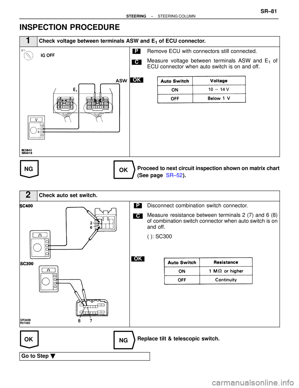
INSPECTION PROCEDURE
1Check voltage between terminals ASW and E1 of ECU connector.
C
OK
PRemove ECU with connectors still connected.
Measure voltage between terminals ASW and E
1 of
ECU connector when auto switch is on and off.
Proceed to next circuit inspection shown on matrix chart
(See page SR±52).
2Check auto set switch.
C
OK
PDisconnect combination switch connector.
Measure resistance between terminals 2 (7) and 6 (8)
of combination switch connector when auto switch is on
and off.
( ): SC300
Replace tilt & telescopic switch.
Go to Step �
±
STEERING STEERING COLUMNSR±81
WhereEverybodyKnowsYourName
Page 2942 of 4087
OKNG
3Check harness and connector between ECU and tilt & telescopic switch (See pa\
ge IN±33).
Repair or replace harness or connector.
Check and replace ECU.
SR±82±
STEERING STEERING COLUMN
WhereEverybodyKnowsYourName
Page 2943 of 4087
±MEMO±
±
STEERING STEERING COLUMNSR±83
WhereEverybodyKnowsYourName
Page 2944 of 4087
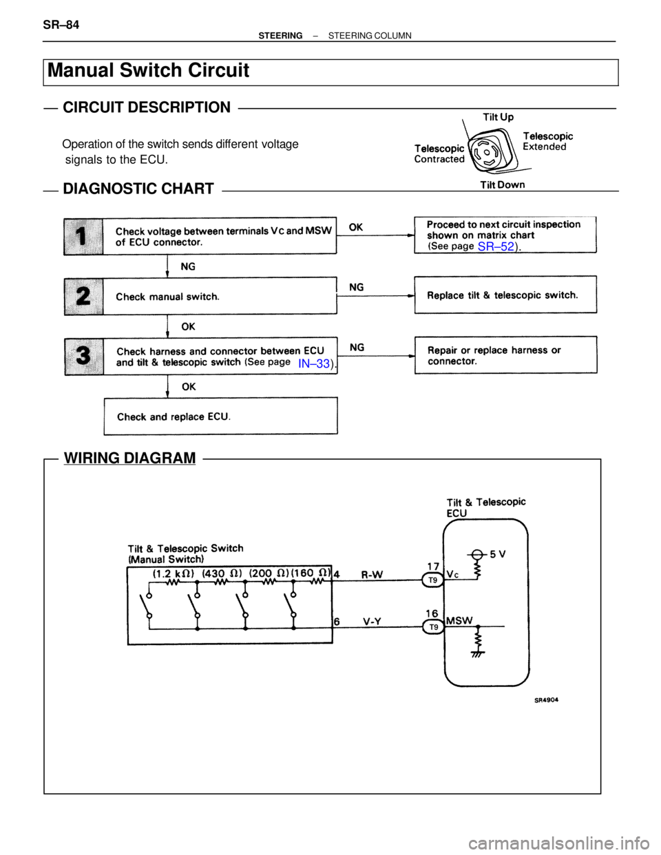
Operation of the switch sends different voltage
signals to the ECU.
SR±52 ).
IN±33 ).
WIRING DIAGRAM
Manual Switch Circuit
CIRCUIT DESCRIPTION
DIAGNOSTIC CHARTDIAGNOSTIC CHART
SR±84±
STEERING STEERING COLUMN
WhereEverybodyKnowsYourName
Page 2945 of 4087
NGOK
OKNG
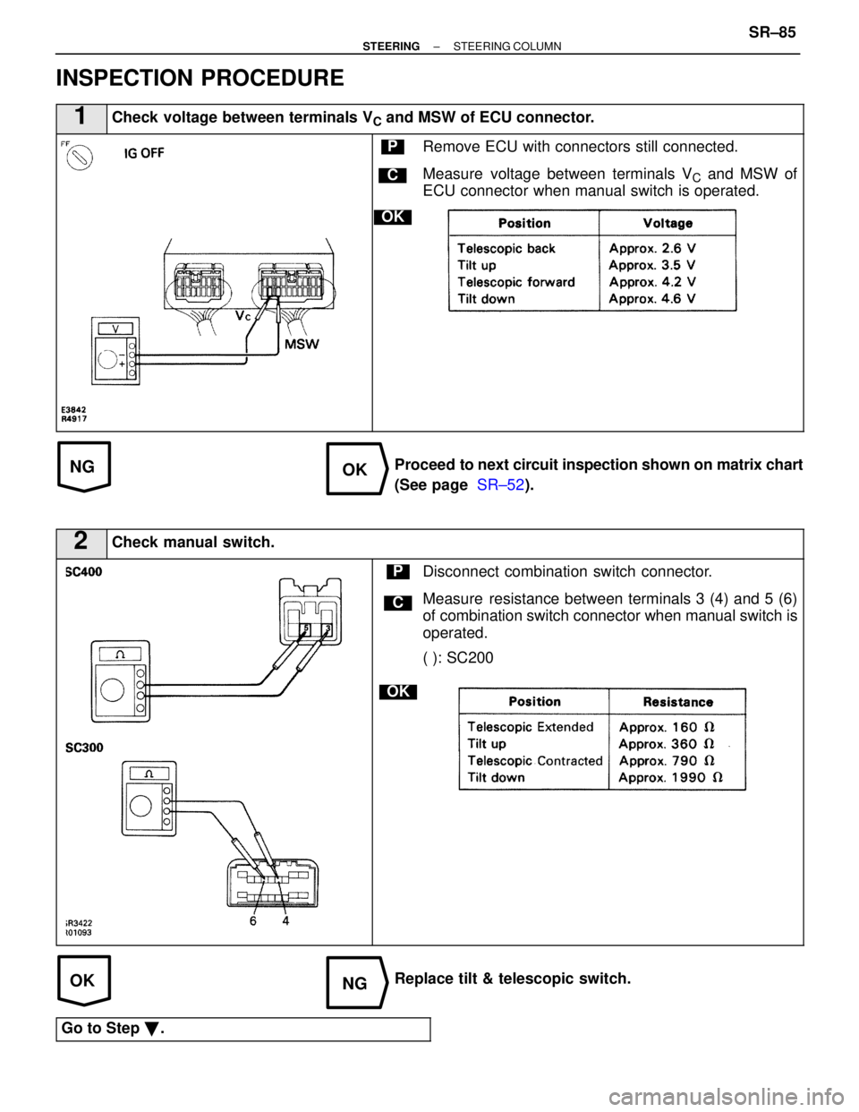
INSPECTION PROCEDURE
1Check voltage between terminals VC and MSW of ECU connector.
C
OK
PRemove ECU with connectors still connected.
Measure voltage between terminals V
C and MSW of
ECU connector when manual switch is operated.
Proceed to next circuit inspection shown on matrix chart
(See page SR±52).
2Check manual switch.
C
OK
PDisconnect combination switch connector.
Measure resistance between terminals 3 (4) and 5 (6)
of combination switch connector when manual switch is
operated.
( ): SC200
Replace tilt & telescopic switch.
Go to Step �.
±
STEERING STEERING COLUMNSR±85
WhereEverybodyKnowsYourName
Page 2946 of 4087
OKNG
3Check harness and connector between ECU and tilt & telescopic switch (See pa\
ge IN±33).
Replace tilt & telescopic switch.
Check and replace ECU.
SR±86±
STEERING STEERING COLUMN
WhereEverybodyKnowsYourName
Page 2947 of 4087
±MEMO±
±
STEERING STEERING COLUMNSR±87
WhereEverybodyKnowsYourName
Page 2948 of 4087
SR±52).
IN±33).
WIRING DIAGRAM
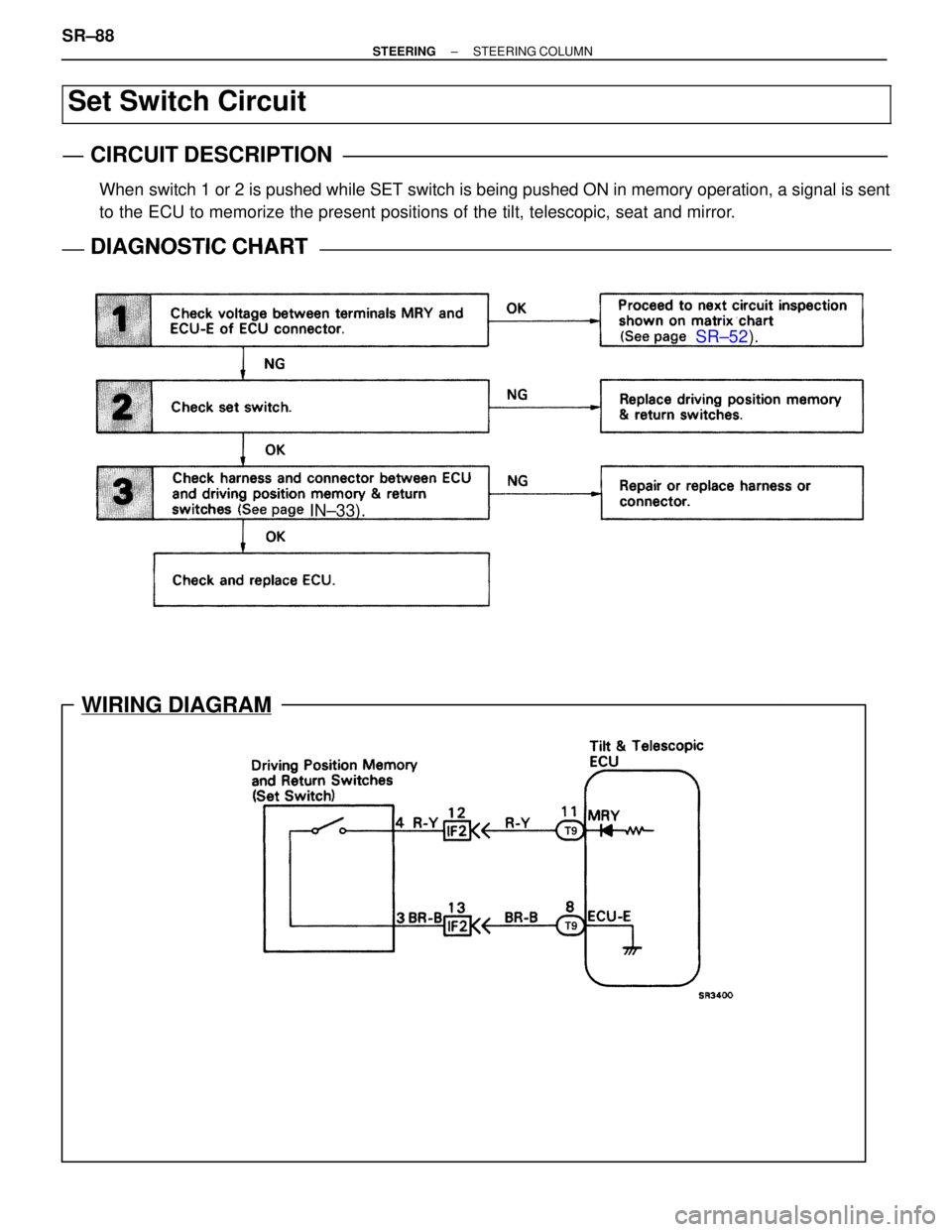
Set Switch Circuit
CIRCUIT DESCRIPTION
When switch 1 or 2 is pushed while SET switch is being pushed ON in memory o\
peration, a signal is sent
to the ECU to memorize the present positions of the tilt, telescopic, seat\
and mirror.
DIAGNOSTIC CHARTDIAGNOSTIC CHART
SR±88±
STEERING STEERING COLUMN
WhereEverybodyKnowsYourName
Page 2949 of 4087
NGOK
OKNG
OKNG
INSPECTION PROCEDURE
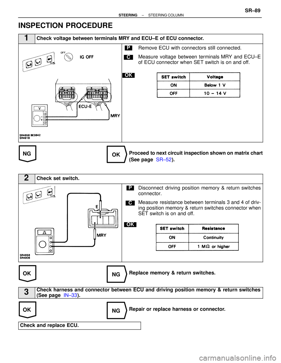
1Check voltage between terminals MRY and ECU±E of ECU connector.
C
OK
PRemove ECU with connectors still connected.
Measure voltage between terminals MRY and ECU±E
of ECU connector when SET switch is on and off.
Proceed to next circuit inspection shown on matrix chart
(See page SR±52).
2Check set switch.
C
OK
PDisconnect driving position memory & return switches
connector.
Measure resistance between terminals 3 and 4 of driv-
ing position memory & return switches connector when
SET switch is on and off.
Replace memory & return switches.
3Check harness and connector between ECU and driving position memory & return switches
(See page IN±33).
Repair or replace harness or connector.
Check and replace ECU.
±
STEERING STEERING COLUMNSR±89
WhereEverybodyKnowsYourName
Page 2950 of 4087
SR±52).
IN±33).
WIRING DIAGRAM
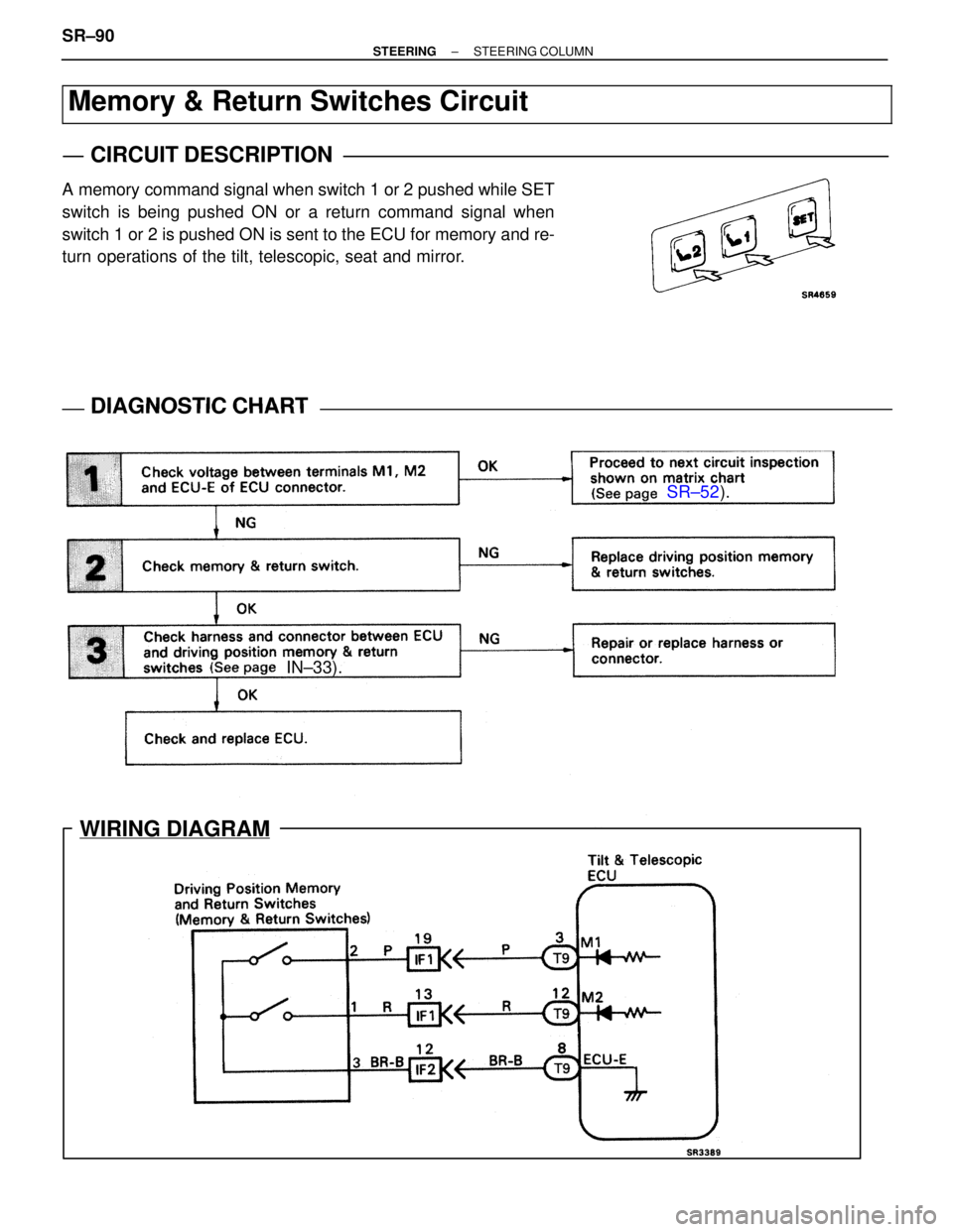
Memory & Return Switches Circuit
CIRCUIT DESCRIPTION
A memory command signal when switch 1 or 2 pushed while SET
switch is being pushed ON or a return command signal when
switch 1 or 2 is pushed ON is sent to the ECU for memory and re-
turn operations of the tilt, telescopic, seat and mirror.
DIAGNOSTIC CHARTDIAGNOSTIC CHART
SR±90±
STEERING STEERING COLUMN
WhereEverybodyKnowsYourName
Trending: brake pads, weight, engine coolant, tire type, hood open, four wheel drive, fold seats
