LEXUS SC400 1991 Service Repair Manual
Manufacturer: LEXUS, Model Year: 1991,
Model line: SC400,
Model: LEXUS SC400 1991
Pages: 4087, PDF Size: 75.75 MB
LEXUS SC400 1991 Service Repair Manual
SC400 1991
LEXUS
LEXUS
https://www.carmanualsonline.info/img/36/57051/w960_57051-0.png
LEXUS SC400 1991 Service Repair Manual
Trending: battery replacement, vacuum, traction control, fuses, water pump, display, four wheel drive
Page 3411 of 4087

STANDARD VALUE OF ECU TERMINALS (Cont'd)
Symbols (Terminals No.)STD Voltage (V)Condition
ISC1 (B35), ISC2 (B34)E1 (B69)10 14IG switch ONISC1 (B35), ISC2 (B34)
ISC3 (B33), ISC4 (B32)±E1 (B69)10 ~ 14IG switch ON
VF1 (B29), VF2 (B28) ± E1 (B69)1.0 ~ 4.0
Maintain engine speed at 2,500 rpm for two
minutes
after warming up then return to idling.
OXL1 (B48), OXR1 (B47) ± E1 (B69)Pulse generation(0 ~ 1.0)Maintain engine speed at 2,500 rpm for two
minutes
after warming up.
HTL1 (B71), HTR1 (B72)E01 (B80)Below 2.0IdlingHTL1 (B71), HTR1 (B72)
HTL2 (B52), HTR2 (B53)± E01 (B80)10 ~ 14IG switch ON
EGR1 (B39), EGR2 (B38)E1 (B69)*10 14IG switch ONEGR1 (B39), EGR2 (B38)
EGR3 (B37), EGR4 (B36)± E1 (B69)* 10 ~ 14IG switch ON
EGR (B39) ± E1 (B69)10 ~ 14IG switch ON
KNK1 (B50), KNK2 (B49) ± E1 (B69)Pulse generation
(Frequency : 6.6 KHz)Idling
NSW (B76) E1 (B69)
10 ~ 14IG switch ON
Other shift position in ºPº, ºNº ranges.
NSW (B76) ± E1 (B69)
Below 1.0IG switch ON
Shift position in ºPº, ºNº ranges.
SPD (A2)±E1 (B69)Pulse generation (0 and 10 ~ 14)IG switch ON
Rotate driving wheel slowly.
TE1 (A20) ± E1 (B69)10 ~ 14IG switch ON
TE2 (A19) ± E1 (B69)10 ~ 14IG switch ON
W (A6) E1 (B69)10 ~ 14IdlingW (A6)±E1 (B69)Below 2.0IG switch ON
AD (A11) ± E1 (B69)10 ~ 14Idling
ODI (A12) ± E1 (B69)4.0 ~ 6.0IG switch ON
A/C (A34) E1 (B69)Bellow 2.0A/C switch ON (At idling)A/C (A34) ± E1 (B69)10 ~ 14A/C switch OFF
ACMG (A23) E1 (B69)Below 2.0A/C switch ON (At idling)ACMG (A23)±E1 (B69)10 ~ 14A/C switch OFF
TR (A37) ± E1 (B69)10 ~ 14IG switch ON
Below 1 0IG switch ON
VTO1 (A40)E2 (B65)
Below 1.0IG switch ON
Main or sub throttle valve fully closed.VTO1 (A40)
VTO2 (A39)± E2 (B65)
30 55IG switch ON()3.0 ~ 5.5IG switch ON
Main or sub throttle valve fully open.
NEO (A38) ± E1 (B69)4.0 ~ 6.0IG switch ON
* Only for USA specification vehicles. TR±34
±
ENGINE TROUBLESHOOTING Standard Value of ECU Terminals
WhereEverybodyKnowsYourName
Page 3412 of 4087
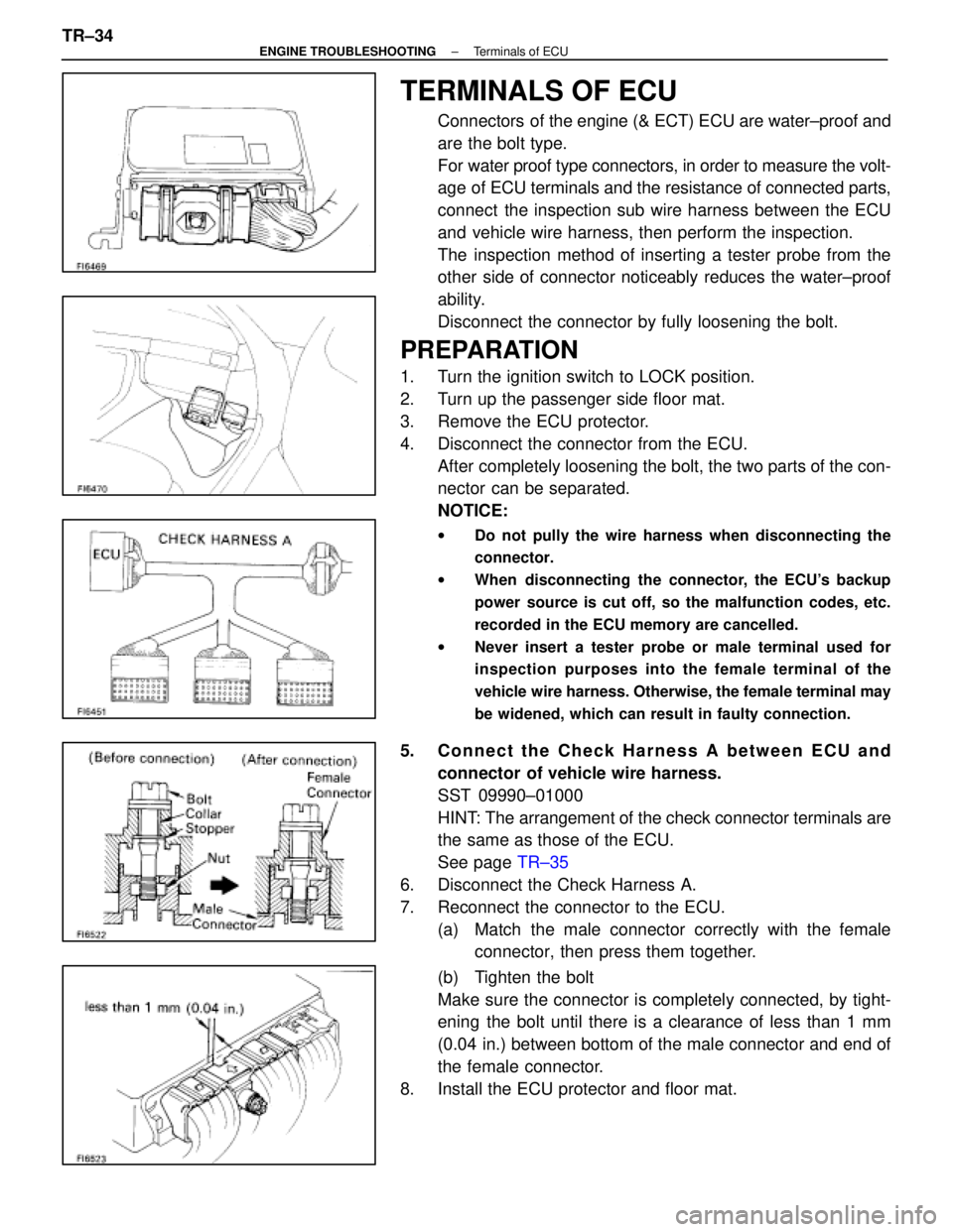
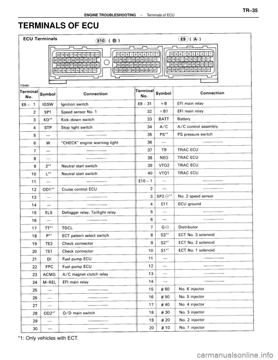
TERMINALS OF ECU
Connectors of the engine (& ECT) ECU are water±proof and
are the bolt type.
For water proof type connectors, in order to measure the volt-
age of ECU terminals and the resistance of connected parts,
connect the inspection sub wire harness between the ECU
and vehicle wire harness, then perform the inspection.
The inspection method of inserting a tester probe from the
other side of connector noticeably reduces the water±proof
ability.
Disconnect the connector by fully loosening the bolt.
PREPARATION
1. Turn the ignition switch to LOCK position.
2. Turn up the passenger side floor mat.
3. Remove the ECU protector.
4. Disconnect the connector from the ECU.After completely loosening the bolt, the two parts of the con-
nector can be separated.
NOTICE:
w Do not pully the wire harness when disconnecting the
connector.
w When disconnecting the connector, the ECU's backup
power source is cut off, so the malfunction codes, etc.
recorded in the ECU memory are cancelled.
w Never insert a tester probe or male terminal used for
inspection purposes into the female terminal of the
vehicle wire harness. Otherwise, the female terminal may
be widened, which can result in faulty connection.
5. Connect the Check Harness A between ECU and
connector of vehicle wire harness.
SST 09990±01000
HINT: The arrangement of the check connector terminals are
the same as those of the ECU.
See page TR±35
6. Disconnect the Check Harness A.
7. Reconnect the connector to the ECU. (a) Match the male connector correctly with the femaleconnector, then press them together.
(b) Tighten the bolt
Make sure the connector is completely connected, by tight-
ening the bolt until there is a clearance of less than 1 mm
(0.04 in.) between bottom of the male connector and end of
the female connector.
8. Install the ECU protector and floor mat.
TR±34
±
ENGINE TROUBLESHOOTING Terminals of ECU
WhereEverybodyKnowsYourName
Page 3413 of 4087
TERMINALS OF ECU
*1: Only vehicles with ECT.
±
ENGINE TROUBLESHOOTING Terminals of ECUTR±35
WhereEverybodyKnowsYourName
Page 3414 of 4087
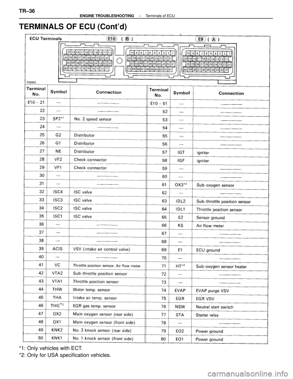
TERMINALS OF ECU (Cont'd)
*1: Only vehicles with ECT.
*2: Only for USA specification vehicles. TR±36
±
ENGINE TROUBLESHOOTING Terminals of ECU
WhereEverybodyKnowsYourName
Page 3415 of 4087
TR±88
TR±10
0
TR±12
2
TR±13
0
TR±13
6
TR±14
0
TR±11
4
TR±14
2 TR±108
TR±11
8
TR±12
4
TR±13
2
AC±84
ST±24
IG±24 IG±6
EM±30
AT±66
IN±32BE±381IG±7
IG±9
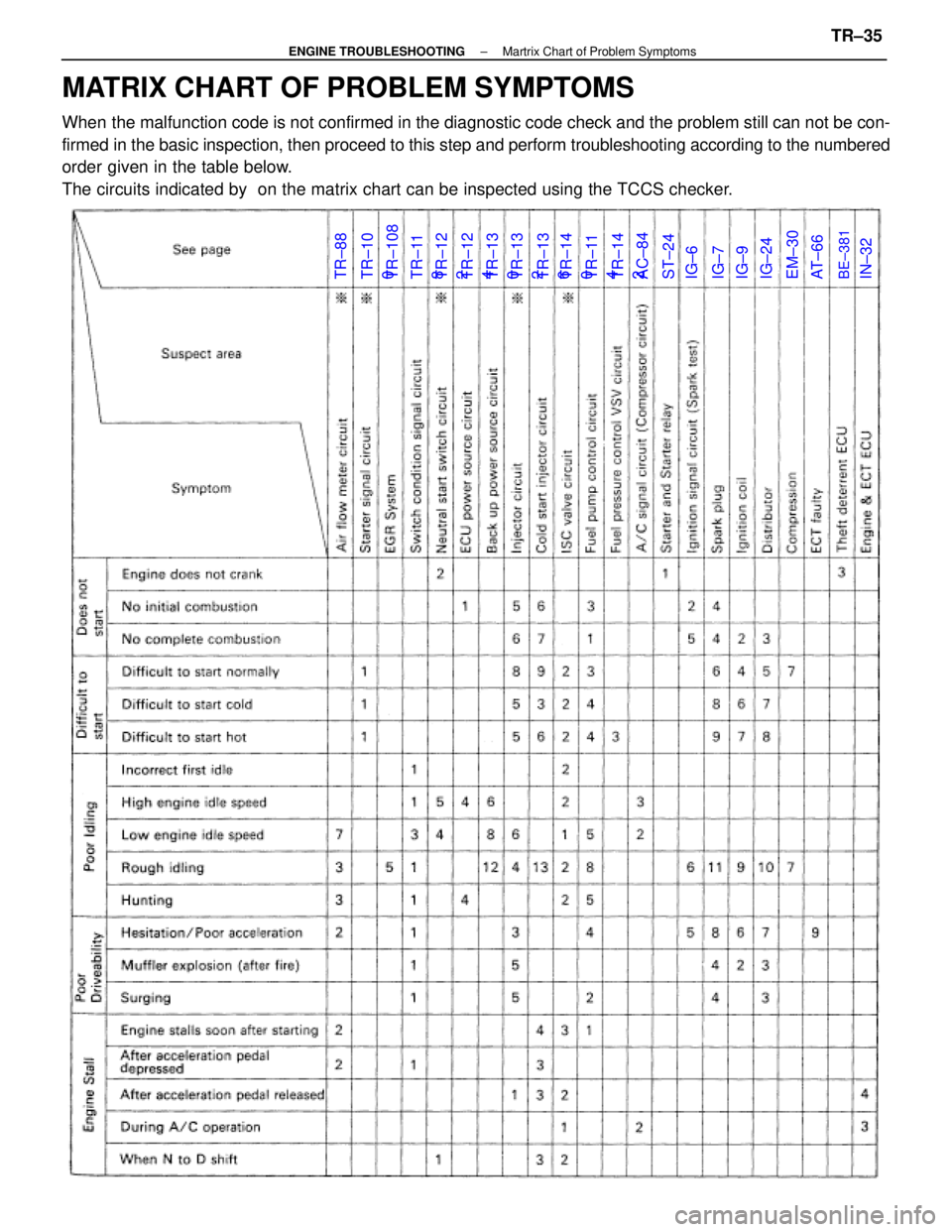
MATRIX CHART OF PROBLEM SYMPTOMS
When the malfunction code is not confirmed in the diagnostic code check and \
the problem still can not be con-
firmed in the basic inspection, then proceed to this step and perform troubles\
hooting according to the numbered
order given in the table below.
The circuits indicated by on the matrix chart can be inspected using th\
e TCCS checker.
±
ENGINE TROUBLESHOOTING Martrix Chart of Problem SymptomsTR±35
WhereEverybodyKnowsYourName
Page 3416 of 4087
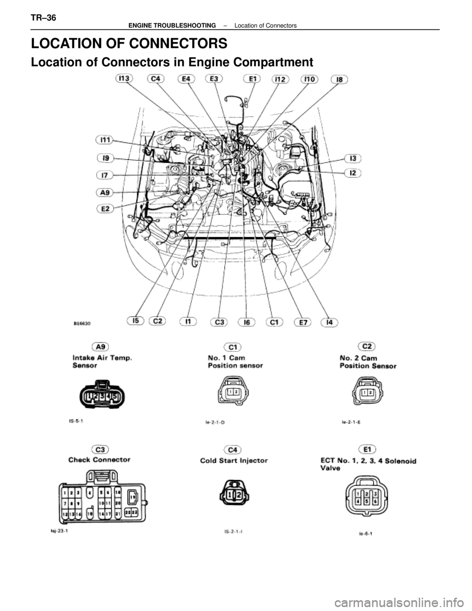
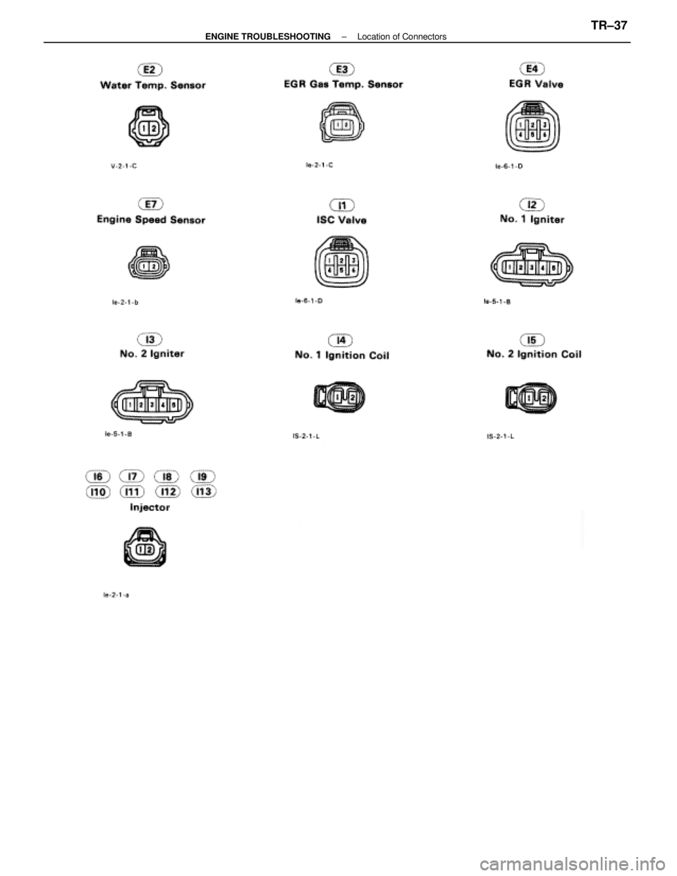
LOCATION OF CONNECTORS
Location of Connectors in Engine Compartment
TR±36±
ENGINE TROUBLESHOOTING Location of Connectors
WhereEverybodyKnowsYourName
Page 3417 of 4087
±
ENGINE TROUBLESHOOTING Location of ConnectorsTR±37
WhereEverybodyKnowsYourName
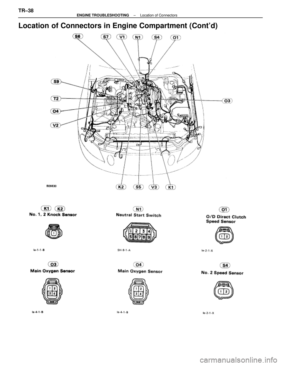
Page 3418 of 4087
Location of Connectors in Engine Compartment (Cont'd)
TR±38±
ENGINE TROUBLESHOOTING Location of Connectors
WhereEverybodyKnowsYourName
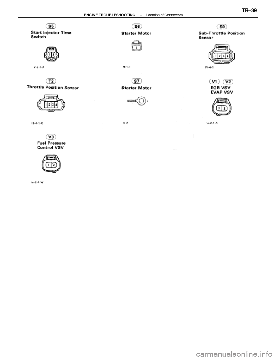
Page 3419 of 4087
±
ENGINE TROUBLESHOOTING Location of ConnectorsTR±39
WhereEverybodyKnowsYourName
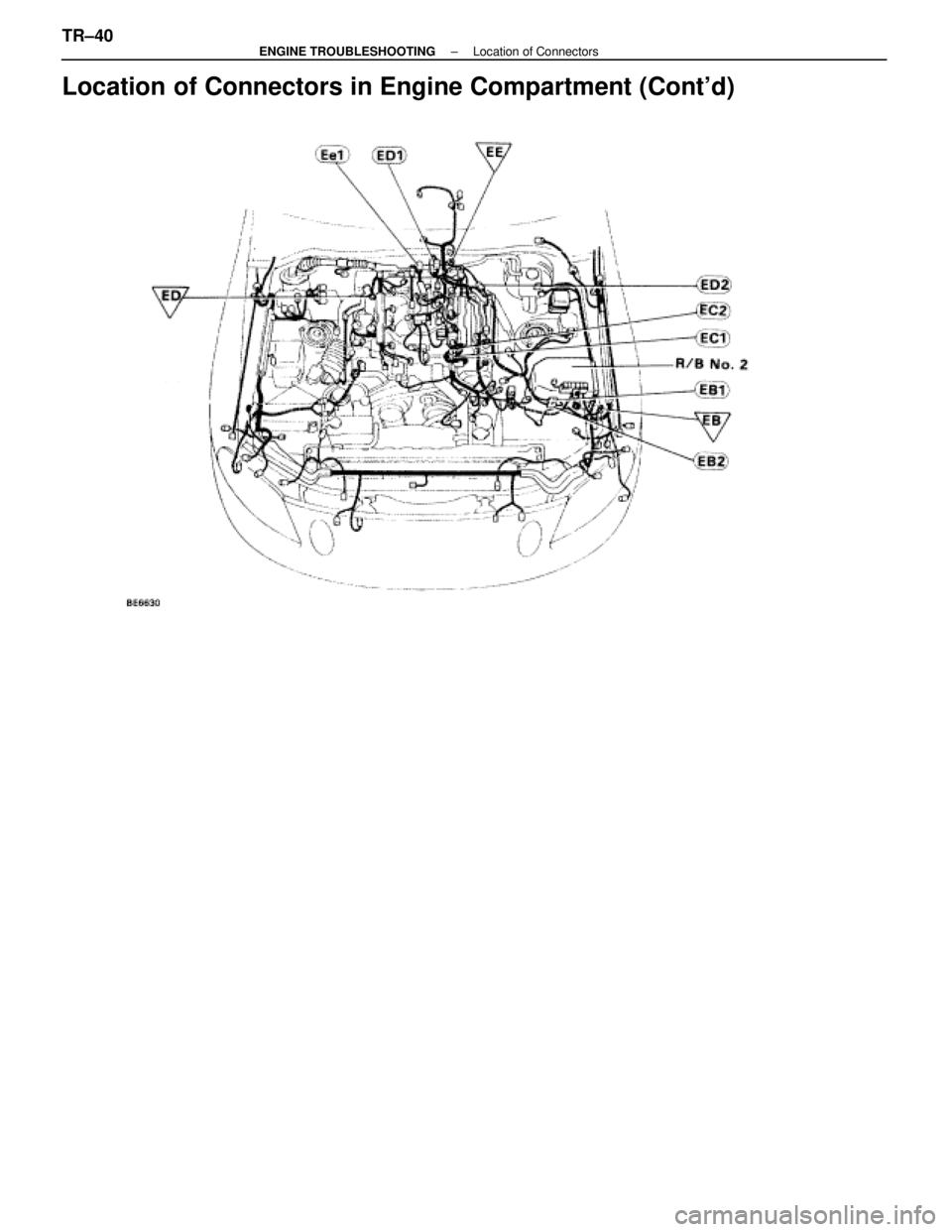
Page 3420 of 4087
Location of Connectors in Engine Compartment (Cont'd)
TR±40±
ENGINE TROUBLESHOOTING Location of Connectors
WhereEverybodyKnowsYourName
Trending: remove seats, brake sensor, engine, headlight bulb, bulb, high beam, brake pads


