LEXUS SC400 1991 Service Repair Manual
Manufacturer: LEXUS, Model Year: 1991,
Model line: SC400,
Model: LEXUS SC400 1991
Pages: 4087, PDF Size: 75.75 MB
LEXUS SC400 1991 Service Repair Manual
SC400 1991
LEXUS
LEXUS
https://www.carmanualsonline.info/img/36/57051/w960_57051-0.png
LEXUS SC400 1991 Service Repair Manual
Trending: exhaust, lights, door lock, wheel bolts, parking brake, spare wheel, suspension
Page 341 of 4087
±MEMO±
±
A304E (1UZ±FE) AUTOMATIC TRANSMISSION TROUBLESHOOTINGAT±101
WhereEverybodyKnowsYourName
Page 342 of 4087
WIRING DIAGRAM
AT±66
IN±33
Throttle Position Sensor Circuit
CIRCUIT DESCRIPTION
The throttle position sensor detects the throttle valve opening angle and s\
ends signals to ECM.
DIAGNOSTIC CHARTDIAGNOSTIC CHART
AT±102±
A304E (1UZ±FE) AUTOMATIC TRANSMISSION TROUBLESHOOTING
WhereEverybodyKnowsYourName
Page 343 of 4087
OKNG
OKNG
OKNG
INSPECTION PROCEDURE
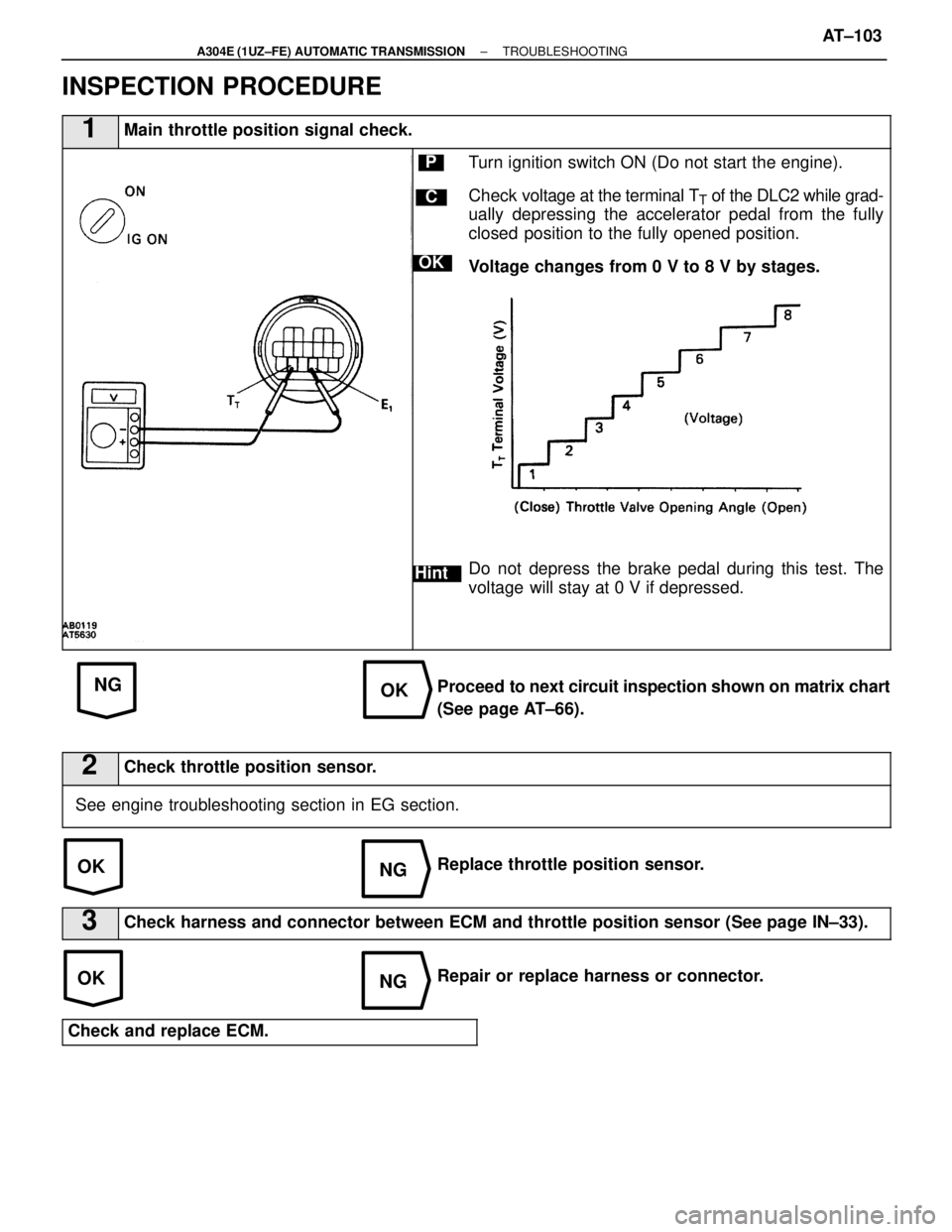
1Main throttle position signal check.
C
OK
Hint
PTurn ignition switch ON (Do not start the engine).
Check voltage at the terminal T
T of the DLC2 while grad-
ually depressing the accelerator pedal from the fully
closed position to the fully opened position.
Voltage changes from 0 V to 8 V by stages.
Do not depress the brake pedal during this test. The
voltage will stay at 0 V if depressed.
Proceed to next circuit inspection shown on matrix chart
(See page AT±66).
2Check throttle position sensor.
See engine troubleshooting section in EG section.
Replace throttle position sensor.
3Check harness and connector between ECM and throttle position sensor (S\
ee page IN±33).
Repair or replace harness or connector.
Check and replace ECM.
±
A304E (1UZ±FE) AUTOMATIC TRANSMISSION TROUBLESHOOTINGAT±103
WhereEverybodyKnowsYourName
Page 344 of 4087
AT±66
IN±33
WIRING DIAGRAM
Kick±down Switch Circuit
CIRCUIT DESCRIPTION
The kick±down switch is turned on when the accelerator ped-
al is depressed beyond the full throttle opening and sends sig-
nals to the ECM.
When the kick±down switch is turned on, the ECM controls
gear shifting according to the programmed shift diagrams.
If a short circuit develops in the kick±down switch, the ECM
disregards the kick±down signals and controls shifting at the
normal shift points.
DIAGNOSTIC CHARTDIAGNOSTIC CHART
AT±104±
A304E (1UZ±FE) AUTOMATIC TRANSMISSION TROUBLESHOOTING
WhereEverybodyKnowsYourName
Page 345 of 4087
OKNG
OKNG
OKNG
INSPECTION PROCEDURE
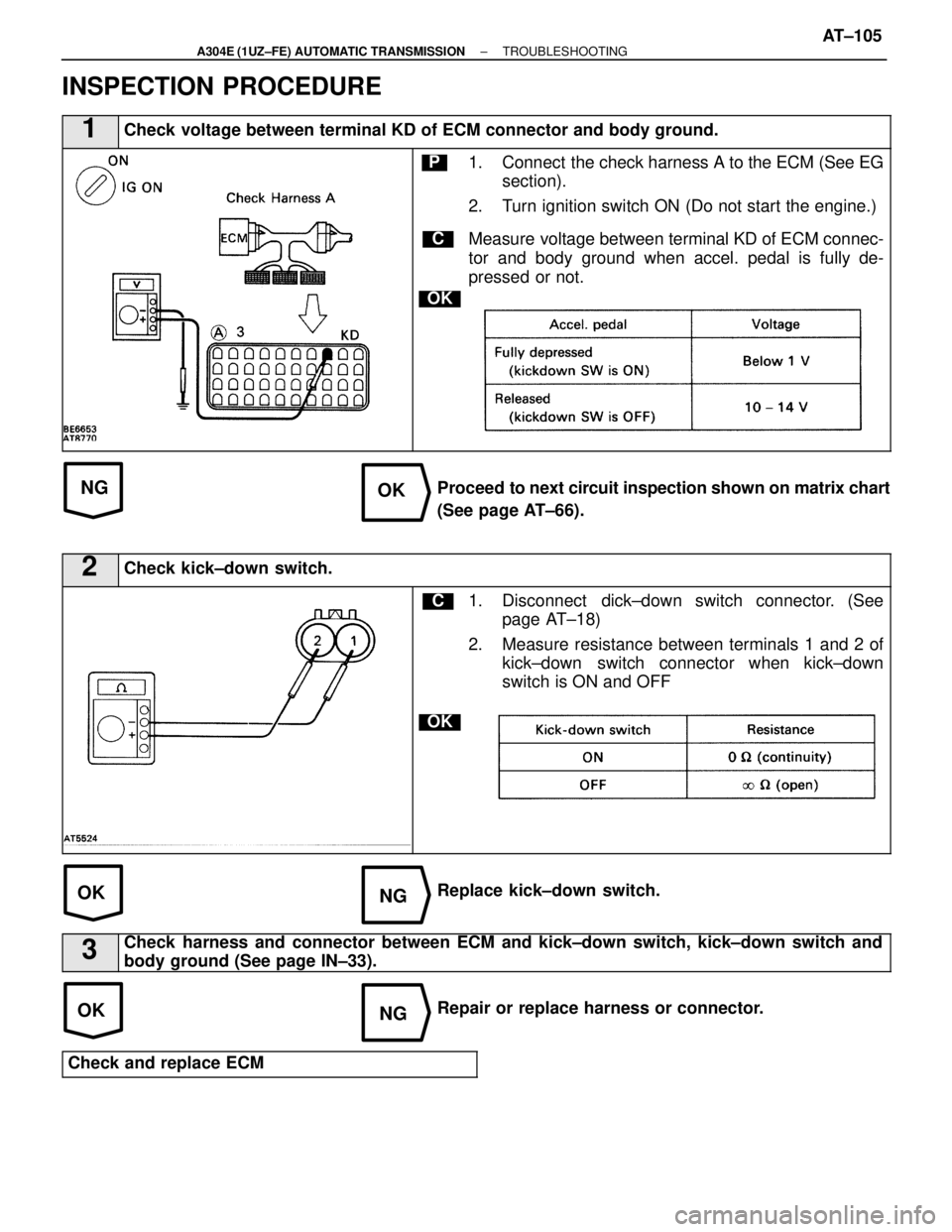
1Check voltage between terminal KD of ECM connector and body ground.
C
OK
P1. Connect the check harness A to the ECM (See EGsection).
2. Turn ignition switch ON (Do not start the engine.)
Measure voltage between terminal KD of ECM connec-
tor and body ground when accel. pedal is fully de-
pressed or not.
Proceed to next circuit inspection shown on matrix chart
(See page AT±66).
2Check kick±down switch.
C
OK
1. Disconnect dick±down switch connector. (See page AT±18)
2. Measure resistance between terminals 1 and 2 of kick±down switch connector when kick±down
switch is ON and OFF
Replace kick±down switch.
3Check harness and connector between ECM and kick±down switch, kick±down\
switch and
body ground (See page IN±33).
Repair or replace harness or connector.
Check and replace ECM
±
A304E (1UZ±FE) AUTOMATIC TRANSMISSION TROUBLESHOOTINGAT±105
WhereEverybodyKnowsYourName
Page 346 of 4087
The park/neutral position switch detects the shift lever
position and sends signals to ECM.The ECM receives
signals (R, PNP, 2 and L) from the park/neutral position
switch. When the signal is not sent to the ECM from the
park/neutral position switch, the ECM judges that the
shift lever is in the D position.
AT±66
IN±33
WIRING DIAGRAM
Park/neutral Position Switch Circuit
CIRCUIT DESCRIPTION
DIAGNOSTIC CHARTDIAGNOSTIC CHART
AT±106±
A304E (1UZ±FE) AUTOMATIC TRANSMISSION TROUBLESHOOTING
WhereEverybodyKnowsYourName
Page 347 of 4087

OKNG
OKNG
OKNG
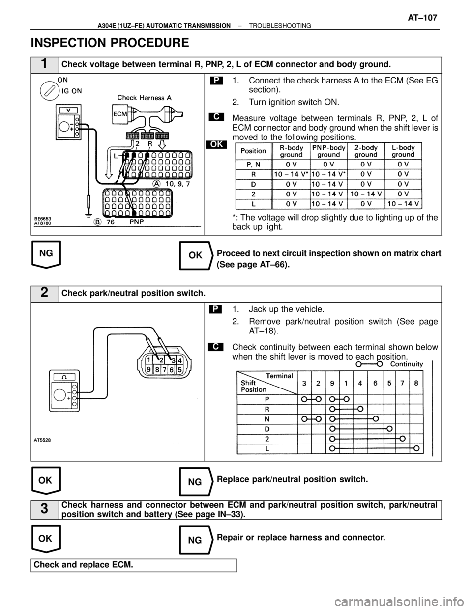
INSPECTION PROCEDURE
1Check voltage between terminal R, PNP, 2, L of ECM connector and body ground.
C
OK
P1. Connect the check harness A to the ECM (See EGsection).
2. Turn ignition switch ON.
Measure voltage between terminals R, PNP, 2, L of
ECM connector and body ground when the shift lever is
moved to the following positions.
*: The voltage will drop slightly due to lighting up of the
back up light.
Proceed to next circuit inspection shown on matrix chart
(See page AT±66).
2Check park/neutral position switch.
C
P1. Jack up the vehicle.
2. Remove park/neutral position switch (See page AT±18).
Check continuity between each terminal shown below
when the shift lever is moved to each position.
Replace park/neutral position switch.
3Check harness and connector between ECM and park/neutral position switch, park\
/neutral
position switch and battery (See page IN±33).
Repair or replace harness and connector.
Check and replace ECM.
±
A304E (1UZ±FE) AUTOMATIC TRANSMISSION TROUBLESHOOTINGAT±107
WhereEverybodyKnowsYourName
Page 348 of 4087
AT±66BE
IN±33
WIRING DIAGRAM
Stop Light Switch Circuit
CIRCUIT DESCRIPTION
The purpose of this circuit is to prevent the engine from stalling, while d\
riving in lockup condition, when
brakes are suddenly applied.When the brake pedal is operated, this switch sends a signal to ECM. Then
the ECM cancels operation of the lockup clutch while braking is in progress\
.
DIAGNOSTIC CHARTDIAGNOSTIC CHART
AT±108±
A304E (1UZ±FE) AUTOMATIC TRANSMISSION TROUBLESHOOTING
WhereEverybodyKnowsYourName
Page 349 of 4087
OKNG
OKNG
OKNG
INSPECTION PROCEDURE
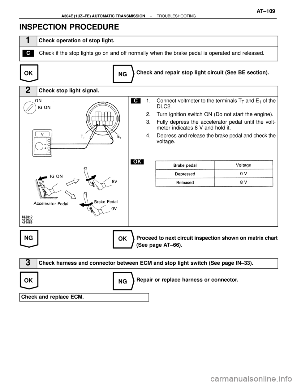
1Check operation of stop light.
Check if the stop lights go on and off normally when the brake pedal is operated and released.C
Check and repair stop light circuit (See BE section).
2Check stop light signal.
C
OK
1. Connect voltmeter to the terminals TT and E1 of the
DLC2.
2. Turn ignition switch ON (Do not start the engine).
3. Fully depress the accelerator pedal until the volt- meter indicates 8 V and hold it.
4. Depress and release the brake pedal and check the
voltage.
Proceed to next circuit inspection shown on matrix chart
(See page AT±66).
3Check harness and connector between ECM and stop light switch (See page\
IN±33).
Repair or replace harness or connector.
Check and replace ECM.
±
A304E (1UZ±FE) AUTOMATIC TRANSMISSION TROUBLESHOOTINGAT±109
WhereEverybodyKnowsYourName
Page 350 of 4087
AT±66
IN±33
WIRING DIAGRAM
Pattern Select Switch Circuit
CIRCUIT DESCRIPTION
The ECM memory contains the shift programs for the NORMAL and POWER pattern\
s, 2 position and L
position and the lock±up patterns. Following the programs corresponding to the\
signals from the pattern
select switch, the park/neutral position switch and other various sensor\
s the ECM switches the solenoid
valves ON and OFF, thereby controlling the transmission gear change and the lock±up cl\
utch operation.
DIAGNOSTIC CHARTDIAGNOSTIC CHART
AT±110±
A304E (1UZ±FE) AUTOMATIC TRANSMISSION TROUBLESHOOTING
WhereEverybodyKnowsYourName
Trending: boot, fuel filter, height, fuel pump, drain bolt, hood release, coolant reservoir


