LEXUS SC400 1991 Service Repair Manual
Manufacturer: LEXUS, Model Year: 1991,
Model line: SC400,
Model: LEXUS SC400 1991
Pages: 4087, PDF Size: 75.75 MB
LEXUS SC400 1991 Service Repair Manual
SC400 1991
LEXUS
LEXUS
https://www.carmanualsonline.info/img/36/57051/w960_57051-0.png
LEXUS SC400 1991 Service Repair Manual
Trending: adding oil, headrest, engine oil, oil type, brakes, radio, fuel type
Page 951 of 4087
OKNG
NGOK
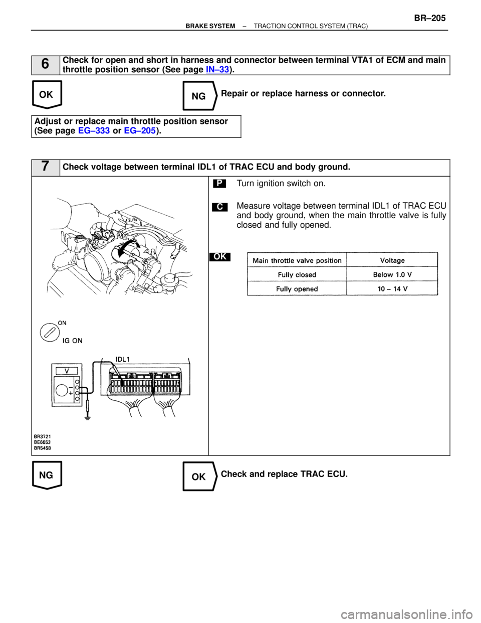
6Check for open and short in harness and connector between terminal VTA1 of ECM and main
throttle position sensor (See page IN±33
).
Repair or replace harness or connector.
Adjust or replace main throttle position sensor
(See page EG±333 or EG±205 ).
7Check voltage between terminal IDL1 of TRAC ECU and body ground.
C
OK
PTurn ignition switch on.
Measure voltage between terminal IDL1 of TRAC ECU
and body ground, when the main throttle valve is fully
closed and fully opened.
Check and replace TRAC ECU.
±
BRAKE SYSTEM TRACTION CONTROL SYSTEM (TRAC)BR±205
WhereEverybodyKnowsYourName
Page 952 of 4087
NGOK
OKNG
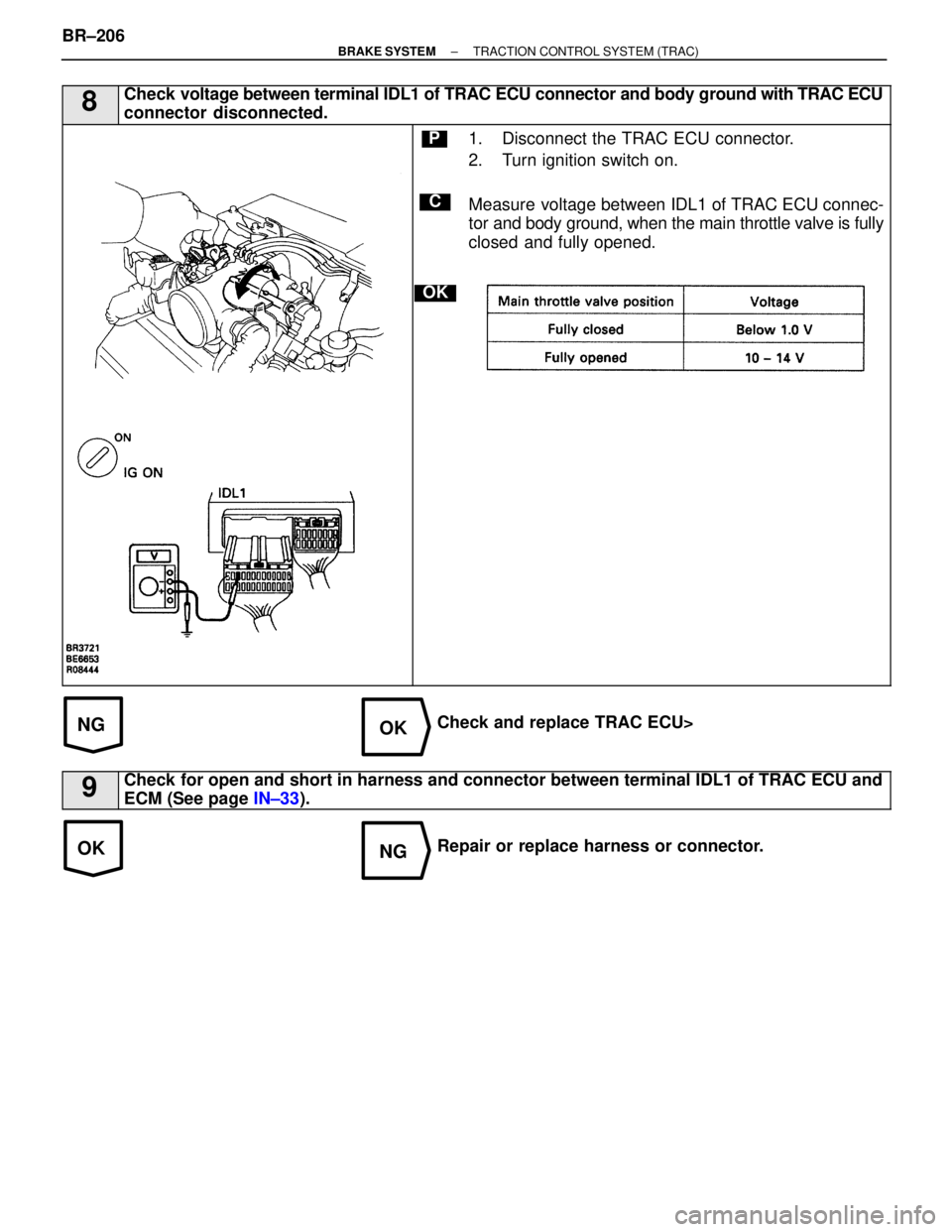
8Check voltage between terminal IDL1 of TRAC ECU connector and body ground with TRAC ECU
connector disconnected.
C
OK
P1. Disconnect the TRAC ECU connector.
2. Turn ignition switch on.
Measure voltage between IDL1 of TRAC ECU connec-
tor and body ground, when the main throttle valve is fully
closed and fully opened.
Check and replace TRAC ECU>
9Check for open and short in harness and connector between terminal IDL1 of TR\
AC ECU and
ECM (See page IN±33).
Repair or replace harness or connector.
BR±206
±
BRAKE SYSTEM TRACTION CONTROL SYSTEM (TRAC)
WhereEverybodyKnowsYourName
Page 953 of 4087
OKNG
10Check main throttle position sensor (See page EG±609 or EG±389 ).
Adjust or replace main throttle position sensor (See
page EG±333 or EG±205).
Check and replace ECM.
±
BRAKE SYSTEM TRACTION CONTROL SYSTEM (TRAC)BR±207
WhereEverybodyKnowsYourName
Page 954 of 4087

DTC47, 48Sub±Throttle Position Sensor Circuit
CIRCUIT DESCRIPTION
This sensor detects the opening angle of the sub±throttle valve and sends the appropriate signals to the ECU.
If a trouble signal is input, the ECU prohibits TRAC control.
DTC No.DTC Detecting ConditionTrouble Area
47
When any of the following (1) through (3) is detected:
(1) Deviation of 5 steps or more to the closedside of the idle step during sub±throttleinitial check.
(2) Voltage at terminal IDL2 switch is OFF evenafter sub±throttle is driven to fully closedposition during
sub±throttle initial check 4.
(3) Voltage at terminal VSH is 1.45 V or morefor at least 0.15 sec. while idle switch is ON.
Sub±throttle position sensor
Open or short in IDL2 circuit
ECM
TRAC ECU
48
Either of the following (1) or (2) continues for atleast
0.12 sec.
(1) Input voltage of TRAC ECU terminal VSH:4.3 V or more.
(2) Input voltage of TRAC ECU terminal VSHis 0.2 V or less while IDL2 switch OFF.
Sub±throttle position sensor
Open or short in VSH circuit
ECM
TRAC ECU
BR±208±
BRAKE SYSTEM TRACTION CONTROL SYSTEM (TRAC)
WhereEverybodyKnowsYourName
Page 955 of 4087
EG±608 or EG±388 ).
EG±333 or EG±205 ).
EG±333 or EG±389 ).
EG±481).
DIAGNOSTIC CHARTDIAGNOSTIC CHART
±
BRAKE SYSTEM TRACTION CONTROL SYSTEM (TRAC)BR±209
WhereEverybodyKnowsYourName
Page 956 of 4087
WIRING DIAGRAM
BR±210±
BRAKE SYSTEM TRACTION CONTROL SYSTEM (TRAC)
WhereEverybodyKnowsYourName
Page 957 of 4087
NOYES
NGOK
OKNG
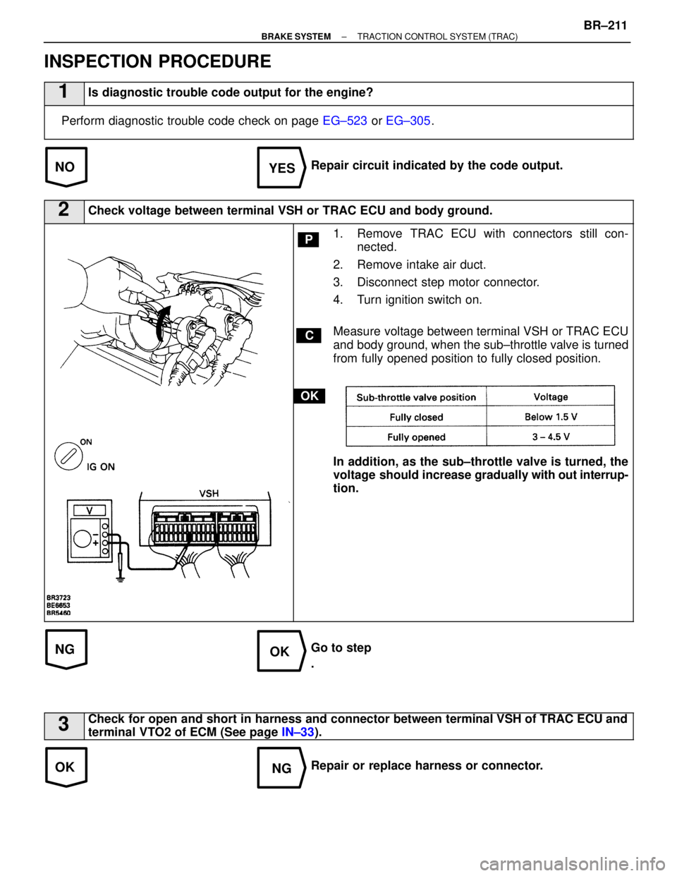
INSPECTION PROCEDURE
1Is diagnostic trouble code output for the engine?
Perform diagnostic trouble code check on page EG±523 or EG±305 .
Repair circuit indicated by the code output.
2Check voltage between terminal VSH or TRAC ECU and body ground.
C
OK
P1. Remove TRAC ECU with connectors still con-
nected.
2. Remove intake air duct.
3. Disconnect step motor connector.
4. Turn ignition switch on.
Measure voltage between terminal VSH or TRAC ECU
and body ground, when the sub±throttle valve is turned
from fully opened position to fully closed position.
In addition, as the sub±throttle valve is turned, the
voltage should increase gradually w ith out interrup-
tion.
Go to step
.
3Check for open and short in harness and connector between terminal VSH of TRAC ECU and
terminal VTO2 of ECM (See page IN±33).
Repair or replace harness or connector.
±
BRAKE SYSTEM TRACTION CONTROL SYSTEM (TRAC)BR±211
WhereEverybodyKnowsYourName
Page 958 of 4087
NGOK
NGOK
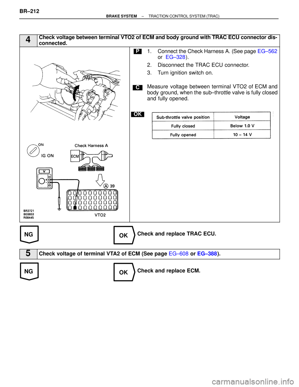
4Check voltage between terminal VTO2 of ECM and body ground with TRAC ECU connector dis-
connected.
C
OK
P1. Connect the Check Harness A. (See page EG±562
or EG±328 ).
2. Disconnect the TRAC ECU connector.
3. Turn ignition switch on.
Measure voltage between terminal VTO2 of ECM and
body ground, when the sub±throttle valve is fully closed
and fully opened.
Check and replace TRAC ECU.
5Check voltage of terminal VTA2 of ECM (See page EG±608 or EG±388 ).
Check and replace ECM.
BR±212
±
BRAKE SYSTEM TRACTION CONTROL SYSTEM (TRAC)
WhereEverybodyKnowsYourName
Page 959 of 4087
OKNG
NGOK
6Check for open and short in harness and connector between terminal VTA2 of ECM and sub±
throttle position sensor (See page IN±33
)
Repair or replace harness or connector.
Adjust or replace sub±throttle position sensor
(See page EG±333 or EG±205 ).
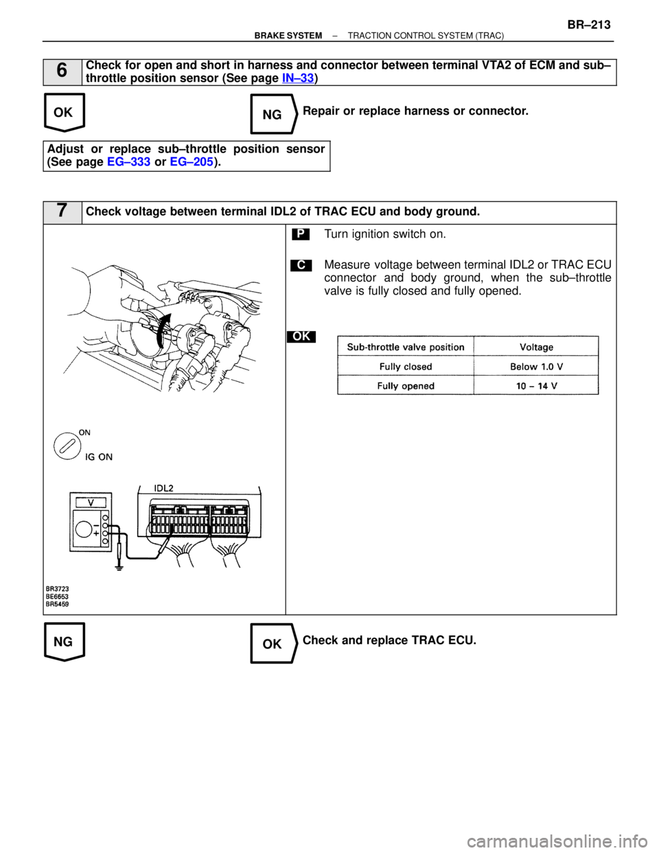
7Check voltage between terminal IDL2 of TRAC ECU and body ground.
C
OK
PTurn ignition switch on.
Measure voltage between terminal IDL2 or TRAC ECU
connector and body ground, when the sub±throttle
valve is fully closed and fully opened.
Check and replace TRAC ECU.
±
BRAKE SYSTEM TRACTION CONTROL SYSTEM (TRAC)BR±213
WhereEverybodyKnowsYourName
Page 960 of 4087
NGOK
OKNG
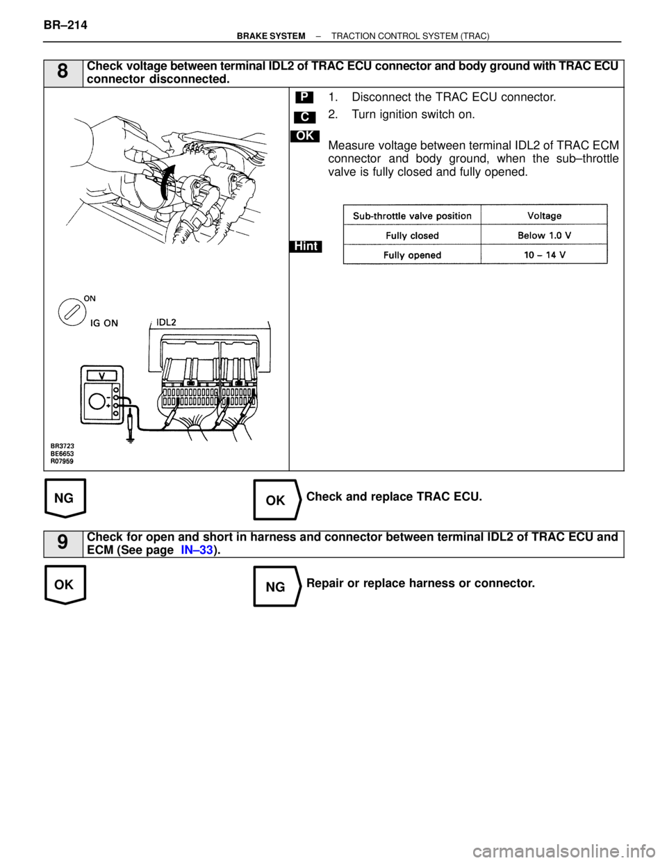
8Check voltage between terminal IDL2 of TRAC ECU connector and body ground with TRAC ECU
connector disconnected.
C
OK
Hint
P1. Disconnect the TRAC ECU connector.
2. Turn ignition switch on.
Measure voltage between terminal IDL2 of TRAC ECM
connector and body ground, when the sub±throttle
valve is fully closed and fully opened.
Check and replace TRAC ECU.
9Check for open and short in harness and connector between terminal IDL2 of TR\
AC ECU and
ECM (See page IN±33).
Repair or replace harness or connector.
BR±214
±
BRAKE SYSTEM TRACTION CONTROL SYSTEM (TRAC)
WhereEverybodyKnowsYourName
Trending: cooling, torque, airbag, turn signal bulb, check transmission fluid, horn, warning light
