LEXUS SC400 1991 Service Repair Manual
Manufacturer: LEXUS, Model Year: 1991,
Model line: SC400,
Model: LEXUS SC400 1991
Pages: 4087, PDF Size: 75.75 MB
LEXUS SC400 1991 Service Repair Manual
SC400 1991
LEXUS
LEXUS
https://www.carmanualsonline.info/img/36/57051/w960_57051-0.png
LEXUS SC400 1991 Service Repair Manual
Trending: radio, brake fluid, ignition buzzer, weight, exhaust, warning, instrument panel
Page 941 of 4087
±MEMO±
±
BRAKE SYSTEM TRACTION CONTROL SYSTEM (TRAC)BR±195
WhereEverybodyKnowsYourName
Page 942 of 4087
WIRING DIAGRAM
DTC43ABS & TRAC ECU Malfunction
CIRCUIT DESCRIPTION
DTC No.DTC Detecting ConditionTrouble Area
43ABS control system or TRAC (BRAKE) control system
or communication circuit is abnormal.
ABS & TRAC ECU
Open or short in BRFA circuit
DIAGNOSTIC CHARTDIAGNOSTIC CHART
BR±196±
BRAKE SYSTEM TRACTION CONTROL SYSTEM (TRAC)
WhereEverybodyKnowsYourName
Page 943 of 4087
NGOK
NGOK
OKNG
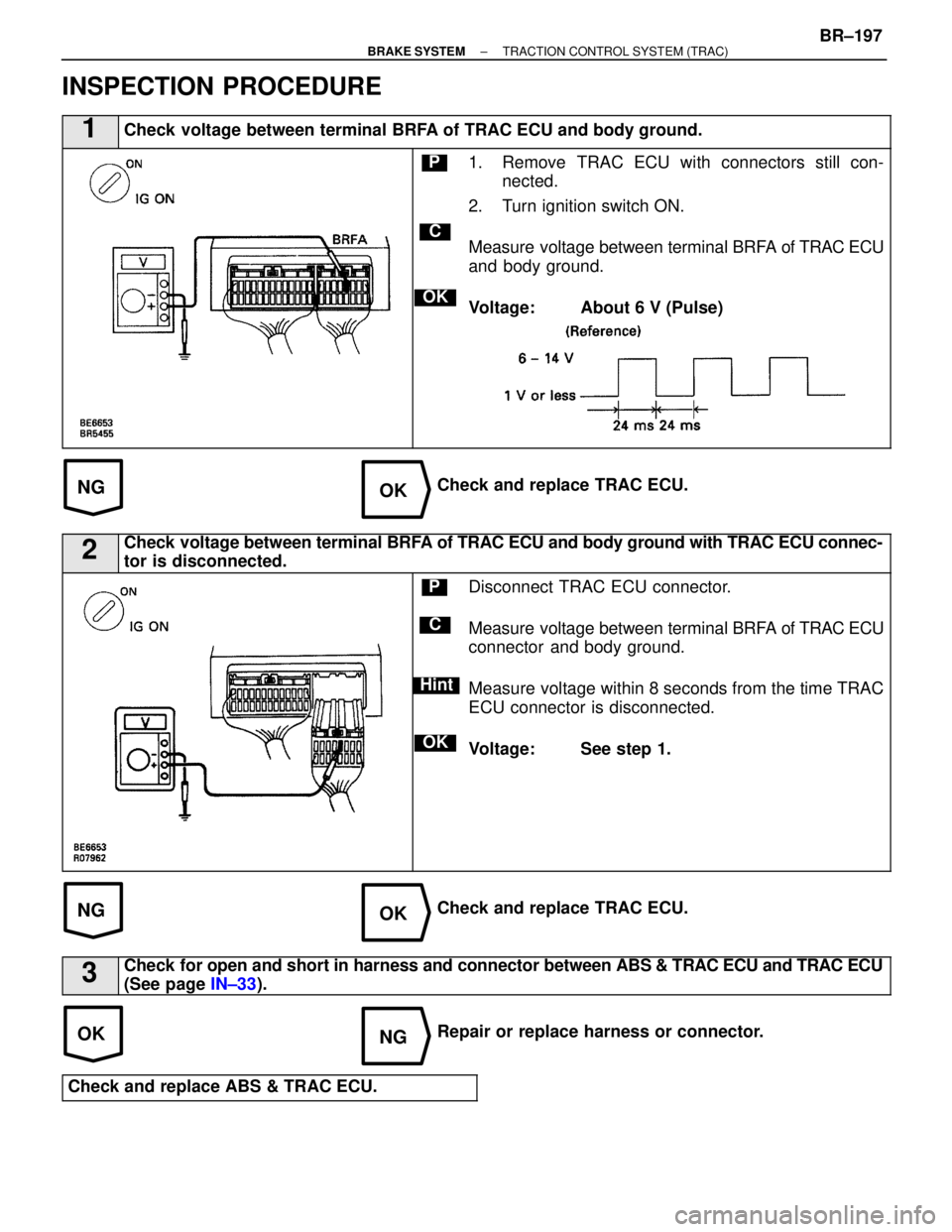
INSPECTION PROCEDURE
1Check voltage between terminal BRFA of TRAC ECU and body ground.
C
OK
P1. Remove TRAC ECU with connectors still con-nected.
2. Turn ignition switch ON.
Measure voltage between terminal BRFA of TRAC ECU
and body ground.
Voltage: About 6 V (Pulse)
Check and replace TRAC ECU.
2Check voltage between terminal BRFA of TRAC ECU and body ground with TRAC ECU connec-
tor is disconnected.
C
OK
Hint
PDisconnect TRAC ECU connector.
Measure voltage between terminal BRFA of TRAC ECU
connector and body ground.
Measure voltage within 8 seconds from the time TRAC
ECU connector is disconnected.
Voltage: See step 1.
Check and replace TRAC ECU.
3Check for open and short in harness and connector between ABS & TRAC ECU and TRAC ECU
(See page IN±33).
Repair or replace harness or connector.
Check and replace ABS & TRAC ECU.
±
BRAKE SYSTEM TRACTION CONTROL SYSTEM (TRAC)BR±197
WhereEverybodyKnowsYourName
Page 944 of 4087
WIRING DIAGRAM
DTC44NE Signal Circuit
CIRCUIT DESCRIPTION
The TRAC ECU receives engine speed signals (NE signals) from the ECM.
DTC No.DTC Detecting ConditionTrouble Area
44No signal is input to terminal NEO 0.24 sec. after trac-
tion control is initiated.
Open or short in NEO circuit
ECM
TRAC ECU
DIAGNOSTIC CHARTDIAGNOSTIC CHART
BR±198±
BRAKE SYSTEM TRACTION CONTROL SYSTEM (TRAC)
WhereEverybodyKnowsYourName
Page 945 of 4087
OKNG
OKNG
INSPECTION PROCEDURES
1Check for open and short in harness and connector between terminal NEO of TRA\
C ECU and
terminal NEO of ECM (See page IN±33).
Repair or replace harness or connector.
2Check voltage between terminal NEO of TRAC ECU and body ground.
C
OK
P1. Remove TRAC ECU with connectors still con-
nected.
2. Turn ignition switch on.
Measure voltage between terminal NEO of TRAC ECU
and body ground for the engine conditions below.
Check and replace TRAC ECU or ECM.
If the same code is still output after the diagnostic code is deleted, che\
ck the contact condition of each
connection.
±
BRAKE SYSTEM TRACTION CONTROL SYSTEM (TRAC)BR±199
WhereEverybodyKnowsYourName
Page 946 of 4087
DTC45, 46Main Throttle Position Sensor Circuit
CIRCUIT DESCRIPTION
This circuit is not directly related to the TRAC control, but as it has an i\
nfluence on TRAC control when trouble
occurs in this circuit, it is used to switch off the TRAC system as a fail safe function.
DTC No.DTC Detecting ConditionTrouble Area
45
Either of the following (1) and (2) continues for 0.12
sec.:
(1) IDL switch of main throttle position sensoris ON.
(2) Input voltage of TRAC ECU terminal VTH:1.45 V or
more.
Main throttle position sensor
Open in VTH circuit
Short in IDL1 circuit
ECM
TRAC ECU
46
Either of the following (1) or (2) continues for0.12 sec.:
(1) Input voltage of TRAC ECU terminal VTH:4.3 V or
more.
(2) Input voltage of TRAC ECU terminal VTHwhile
IDL1 switch is OFF: 0.2 V or less
Main throttle position sensor
Short in VTH circuit
ECM
TRAC ECU
BR±200±
BRAKE SYSTEM TRACTION CONTROL SYSTEM (TRAC)
WhereEverybodyKnowsYourName
Page 947 of 4087
EG±608 or EG±388 ).
EG±333 or EG±205 ).
EG±609 or EG±389 ).
EG±481).
DIAGNOSTIC CHARTDIAGNOSTIC CHART
±
BRAKE SYSTEM TRACTION CONTROL SYSTEM (TRAC)BR±201
WhereEverybodyKnowsYourName
Page 948 of 4087
WIRING DIAGRAM
BR±202±
BRAKE SYSTEM TRACTION CONTROL SYSTEM (TRAC)
WhereEverybodyKnowsYourName
Page 949 of 4087
NOYES
NGOK
OKNG
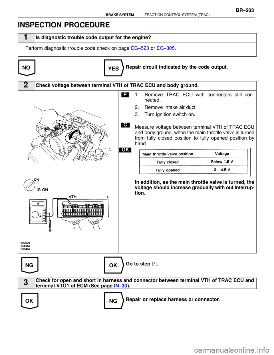
INSPECTION PROCEDURE
1Is diagnostic trouble code output for the engine?
Perform diagnostic trouble code check on page EG±523 or EG±305 .
Repair circuit indicated by the code output.
2Check voltage between terminal VTH of TRAC ECU and body ground.
C
OK
P1. Remove TRAC ECU with connectors still con-
nected.
2. Remove intake air duct.
3. Turn ignition switch on.
Measure voltage between terminal VTH of TRAC ECU
and body ground, when the main throttle valve is turned
from fully closed position to fully opened position by
hand
In addition, as the main throttle valve is turned, the
voltage should increase gradually w ith out interrup-
tion.
Go to step �.
3Check for open and short in harness and connector between terminal VTH o\
f TRAC ECU and
terminal VTO1 of ECM (See page IN±33).
Repair or replace harness or connector.
±
BRAKE SYSTEM TRACTION CONTROL SYSTEM (TRAC)BR±203
WhereEverybodyKnowsYourName
Page 950 of 4087
NGOK
NGOK
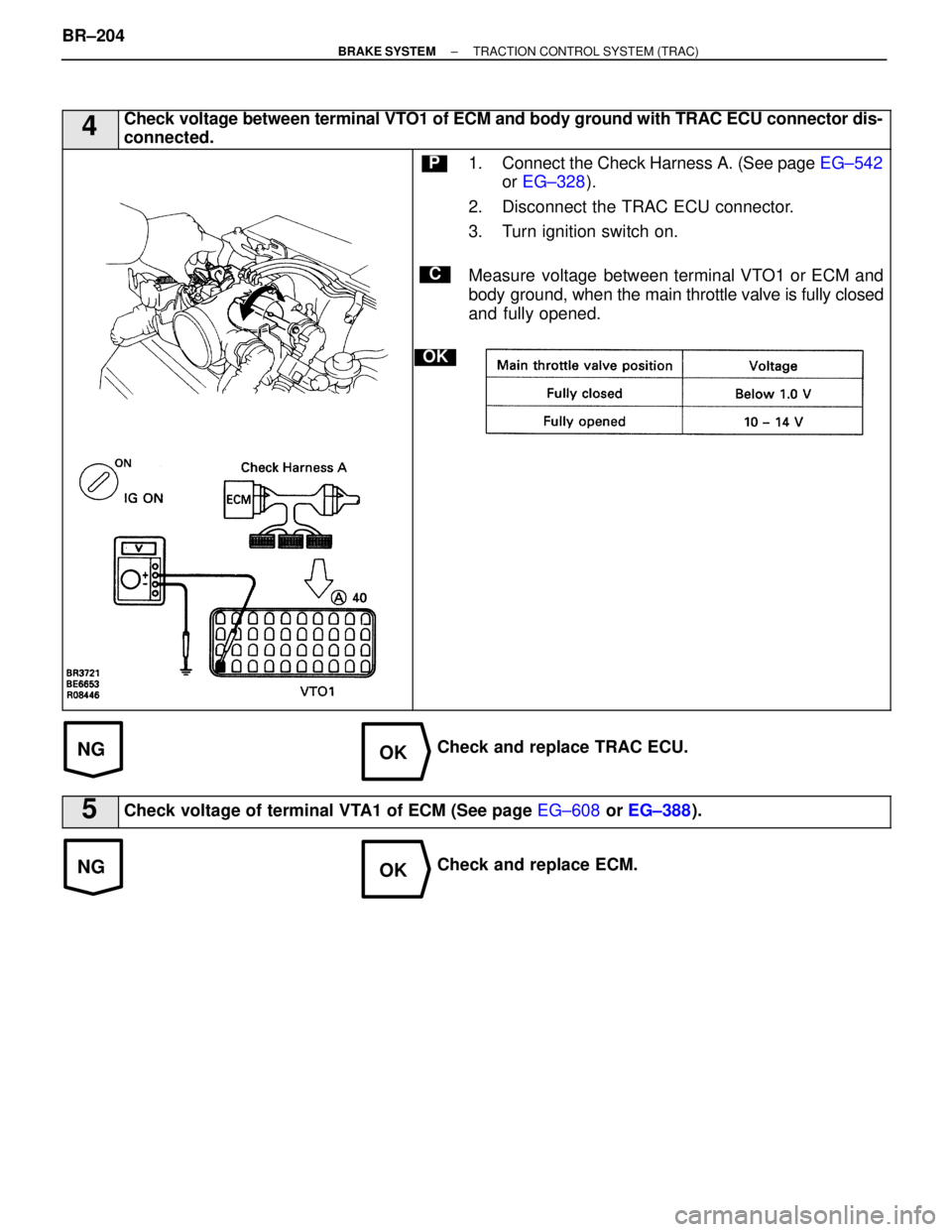
4Check voltage between terminal VTO1 of ECM and body ground with TRAC ECU connector dis-
connected.
C
OK
P1. Connect the Check Harness A. (See page EG±542
or EG±328 ).
2. Disconnect the TRAC ECU connector.
3. Turn ignition switch on.
Measure voltage between terminal VTO1 or ECM and
body ground, when the main thro ttle valve is fully closed
and fully opened.
Check and replace TRAC ECU.
5Check voltage of terminal VTA1 of ECM (See page EG±608 or EG±388 ).
Check and replace ECM.
BR±204
±
BRAKE SYSTEM TRACTION CONTROL SYSTEM (TRAC)
WhereEverybodyKnowsYourName
Trending: fold seats, lumbar support, oil capacity, brake light, low oil pressure, coolant level, headrest


