LINCOLN BLACKWOOD 2003 Owners Manual
Manufacturer: LINCOLN, Model Year: 2003, Model line: BLACKWOOD, Model: LINCOLN BLACKWOOD 2003Pages: 280, PDF Size: 4.2 MB
Page 171 of 280
Installing the snowplow
Read the following instructions before installing a snowplow:
•Front GAWR must not exceed 63% of the GVW. Add ballast weight to
the back of the vehicle, if necessary. Refer to the Safety Compliance
Certification Label to find your vehicle’s front GAWR.
•The Front Axle Accessory Reserve Capacity and the TARC listed on
the bottom right of the Safety Compliance Certification Label will
determine whether or not the addition of a snowplow will overload
your vehicle.
•The weight of the snowplow and supporting components distributed to
the front axle must not exceed the Front Axle Accessory Reserve
Capacity.
•The total weight of the snowplow and aftermarket equipment must
not exceed the TARC.
•The weight of the installed snowplow and aftermarket equipment must
not load the vehicle beyond the GAWR (front/rear) and GVWR listed
on the Safety Compliance Certification Label.
•The total weight of the snowplow and aftermarket equipment must be
considered part of the payload and must not exceed the GCWR for
towing.
•Federal and most local regulations require additional exterior lamps
for snowplow-equipped vehicles. Consult your dealer for additional
information.
•Tires have their maximum inflation pressure and associated load rating
imprinted on the tire sidewall. This pressure may or may not be the
same as that shown as recommended on the vehicle. The vehicle
operator may have to adjust the tire inflation pressure to
accommodate the snowplow and payload. Consult your dealer or
equipment installer for help with proper inflation pressures.
•Federal and some local regulations require additional exterior lamps
for snowplow-equipped vehicles. Consult your dealer for additional
information.
•After installing a snowplow to the vehicle, ensure the vehicle’s front
toe alignment and front ride height are within specification (reset if
required). These specifications are located in the vehicle’s Workshop
Manual.
Note:Do not exceed the GVWR or the GAWR specified on the
certification label.
Driving
171
Page 172 of 280
Removing snowplow
After removing a snowplow from the vehicle, ensure the vehicle’s front
toe alignment and front ride height are within specification (reset if
required).
Snowplowing with your air bag equipped vehicle
Your vehicle is equipped with a driver and passenger air bag
Supplemental Restraint System (SRS) The SRS is designed to activate in
certain frontal and offset frontal collisions when the vehicle sustains
sufficient longitudinal deceleration.
Careless or high speed driving while plowing snow which results in
sufficient vehicle decelerations can deploy the air bag. Such driving also
increases the risk of accidents.
All occupants of the vehicle, including the driver, should always
properly wear their safety belts, even when an air bag (SRS) is
provided.
Never remove or defeat the“tripping mechanisms”designed into the
snow removal equipment by its manufacturer. Doing so may cause
damage to the vehicle and the snow removal equipment as well as
possible air bag deployment.
Do not attempt to service, repair, or modify the Air Bag
Supplemental Restraint System or its fuses. See your Ford or
Lincoln Mercury dealer.
Additional equipment such as snowplow equipment may effect
the performance of the air bag sensors increasing the risk of
injury. Please refer to the Body Builders Layout Book for instructions
about the appropriate installation of additional equipment.
Engine temperature while plowing
When driving with a plow, your engine may run at a higher temperature
than normal because the attached snowplow blade will restrict airflow to
the radiator.
If you are driving more than 24 km (15 miles) at temperatures above
freezing, angle the plow blade either full left or full right to provide
maximum airflow to the radiator.
If you are driving less than 24 km (15 miles) at speeds up to 64 km/h
(40 mph) in cold weather, you will not need to worry about blade
position to provide maximum airflow.
Driving
172
Page 173 of 280
Transmission operation while plowing
•Shift transfer case to 4L (4WD Low) when plowing in small areas at
speeds below 8 km/h (5 mph).
•Shift transfer case to 4H (4WD High) when plowing larger areas or
light snow at higher speeds. Do not exceed 24 km/h (15 mph).
•Do not shift the transmission from a forward gear to R (Reverse) until
the engine is at idle and the wheels are stopped.
•If the vehicle is stuck, shift the transmission in a steady motion
between forward and reverse gears. Do not rock the vehicle for more
than a few minutes. The transmission and tires may be damaged or
the engine can overheat.
Do not rock the vehicle if the engine is not at operating
temperature. Do not rock the vehicle for more than a minute. The
transmission and tires may be damaged or the engine may
overheat.
Do not spin the wheels at over 35 mph (55 km/h). The tires may
fail and injure a passenger or bystander.
Driving
173
Page 174 of 280
GETTING ROADSIDE ASSISTANCE
To fully assist you should you have a vehicle concern, Ford Motor
Company offers a complimentary roadside assistance program. This
program is separate from the New Vehicle Limited Warranty. The service
is available:
•24–hours, seven days a week
•
for the New Vehicle Limited Warranty period of three years or 60,000 km
(36,000 miles), whichever occurs first on Ford and Mercury vehicles,
and four years or 80,000 km (50,000 miles) on Lincoln vehicles.
Roadside assistance will cover:
•changing a flat tire
•jump-starts
•lock-out assistance
•limited fuel delivery
•towing of your disabled vehicle to the nearest Ford Motor Company
dealership, or your selling dealer if within 56.3 km (35 miles) of the
nearest Ford Motor Company dealership (one tow per disablement).
Even non-warranty related tows, like accidents or getting stuck in the
mud or snow, are covered (some exclusions apply, such as impound
towing or repossession).
Canadian customers refer to your Owner Information Guide for
information on:
•coverage period
•exact fuel amounts
•towing of your disabled vehicle
•emergency travel expense reimbursement
•travel planning benefits
USING ROADSIDE ASSISTANCE
Complete the roadside assistance identification card and place it in your
wallet for quick reference. In the United States, this card is found in the
Owner Guide portfolio in the glove compartment in Ford vehicles and is
mailed to you if you own a Mercury or Lincoln. In Canada, the card is
found in the Owner Information Guide in the glove compartment.
U.S. Ford or Mercury vehicle customers who require roadside assistance,
call 1–800–241–3673; Lincoln vehicle customers call 1–800–521–4140.
Roadside Emergencies
174
Page 175 of 280
Canadian customers who require roadside assistance, call
1–800–665–2006.
If you need to arrange roadside assistance for yourself, Ford Motor
Company will reimburse a reasonable amount. To obtain reimbursement
information, U.S. Ford or Mercury vehicles customers call
1-800-241-3673; Lincoln vehicle customers call 1–800–521–4140.
Canadian customers who need to obtain reimbursement information, call
1–800–665–2006.
ROADSIDE COVERAGE BEYOND BASIC WARRANTY
In the United States, you may purchase additional roadside assistance
coverage beyond this period through the Ford Auto Club by contacting
your Ford or Lincoln Mercury dealer.
Similarly in Canada, for uninterrupted Roadside Assistance coverage, you
may purchase extended coverage prior to your Basic Warranty’s Roadside
Assistance expiring. For more information and enrollment, contact
1–877–294–2582 or visit our website at www.ford.ca.
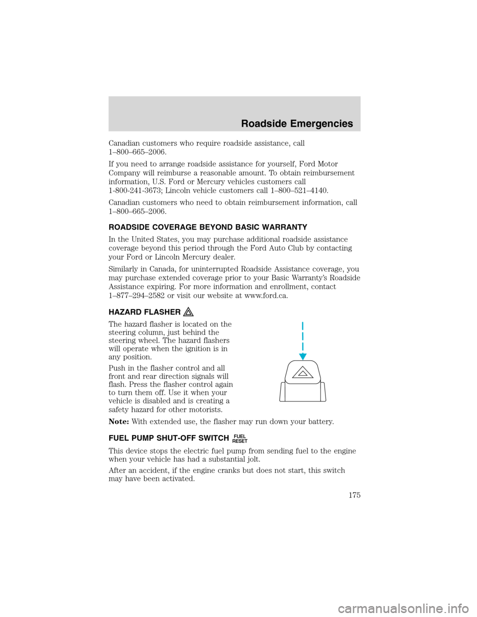
HAZARD FLASHER
The hazard flasher is located on the
steering column, just behind the
steering wheel. The hazard flashers
will operate when the ignition is in
any position.
Push in the flasher control and all
front and rear direction signals will
flash. Press the flasher control again
to turn them off. Use it when your
vehicle is disabled and is creating a
safety hazard for other motorists.
Note:With extended use, the flasher may run down your battery.
FUEL PUMP SHUT-OFF SWITCH
FUEL
RESET
This device stops the electric fuel pump from sending fuel to the engine
when your vehicle has had a substantial jolt.
After an accident, if the engine cranks but does not start, this switch
may have been activated.
Roadside Emergencies
175
Page 176 of 280
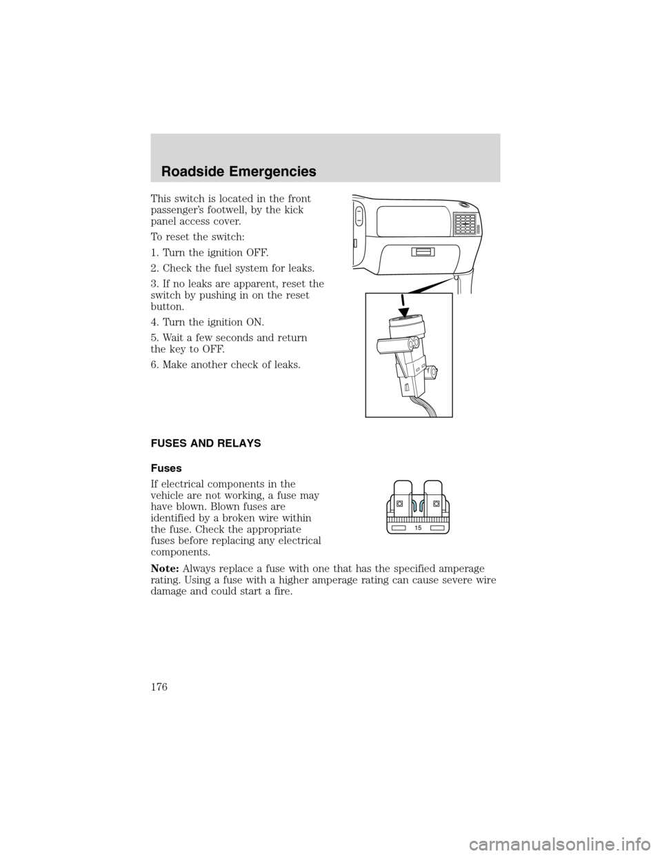
This switch is located in the front
passenger’s footwell, by the kick
panel access cover.
To reset the switch:
1. Turn the ignition OFF.
2. Check the fuel system for leaks.
3. If no leaks are apparent, reset the
switch by pushing in on the reset
button.
4. Turn the ignition ON.
5. Wait a few seconds and return
the key to OFF.
6. Make another check of leaks.
FUSES AND RELAYS
Fuses
If electrical components in the
vehicle are not working, a fuse may
have blown. Blown fuses are
identified by a broken wire within
the fuse. Check the appropriate
fuses before replacing any electrical
components.
Note:Always replace a fuse with one that has the specified amperage
rating. Using a fuse with a higher amperage rating can cause severe wire
damage and could start a fire.
15
Roadside Emergencies
176
Page 177 of 280
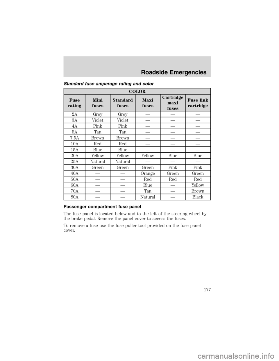
Standard fuse amperage rating and color
COLOR
Fuse
ratingMini
fusesStandard
fusesMaxi
fusesCartridge
maxi
fusesFuse link
cartridge
2A Grey Grey———
3A Violet Violet———
4A Pink Pink———
5A Tan Tan———
7.5A Brown Brown———
10A Red Red———
15A Blue Blue———
20A Yellow Yellow Yellow Blue Blue
25A Natural Natural———
30A Green Green Green Pink Pink
40A——Orange Green Green
50A——Red Red Red
60A——Blue—Yellow
70A——Ta n—Brown
80A——Natural—Black
Passenger compartment fuse panel
The fuse panel is located below and to the left of the steering wheel by
the brake pedal. Remove the panel cover to access the fuses.
To remove a fuse use the fuse puller tool provided on the fuse panel
cover.
Roadside Emergencies
177
Page 178 of 280
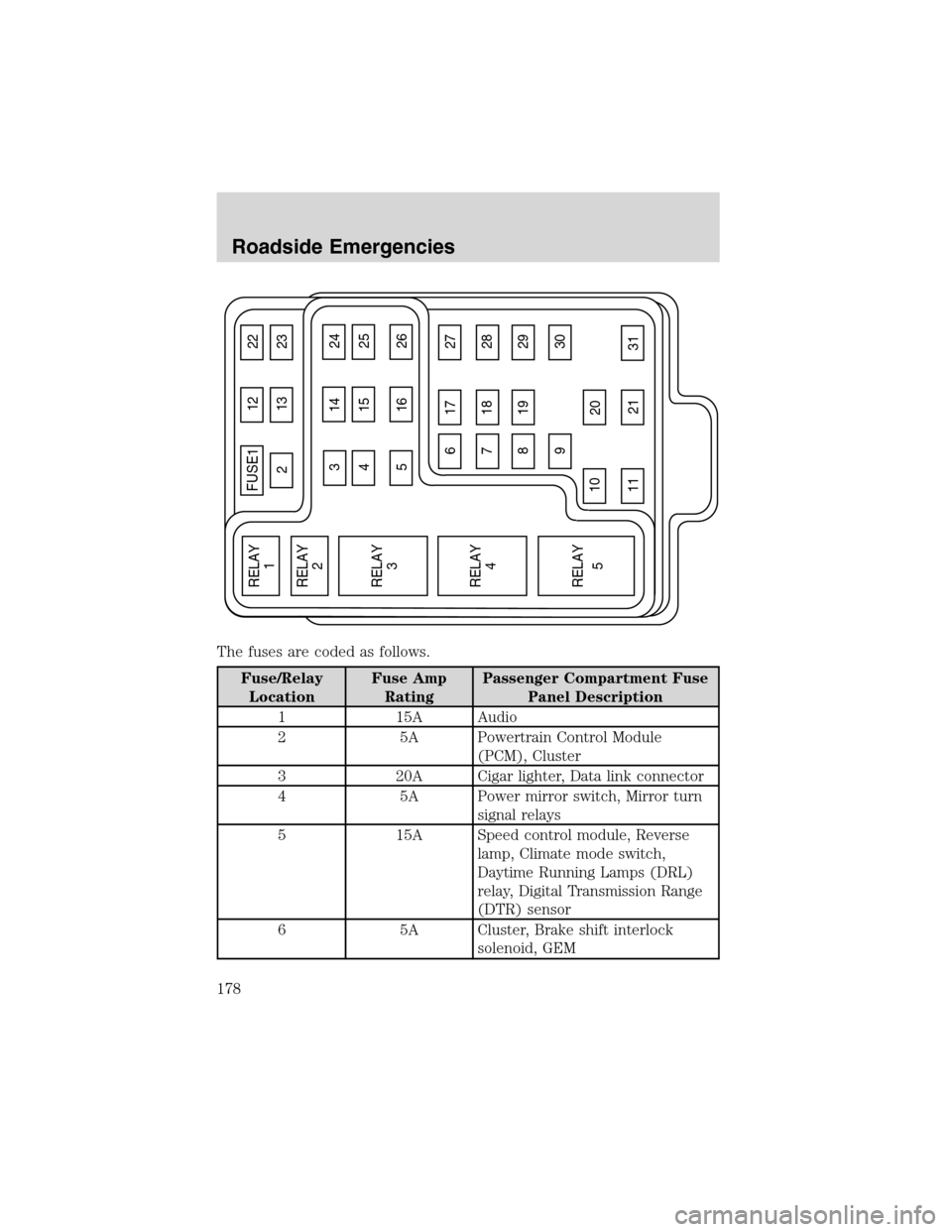
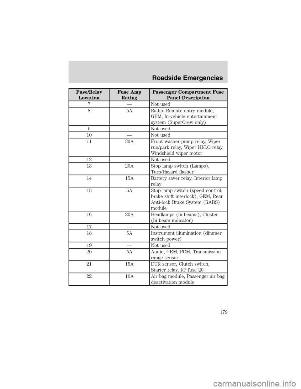
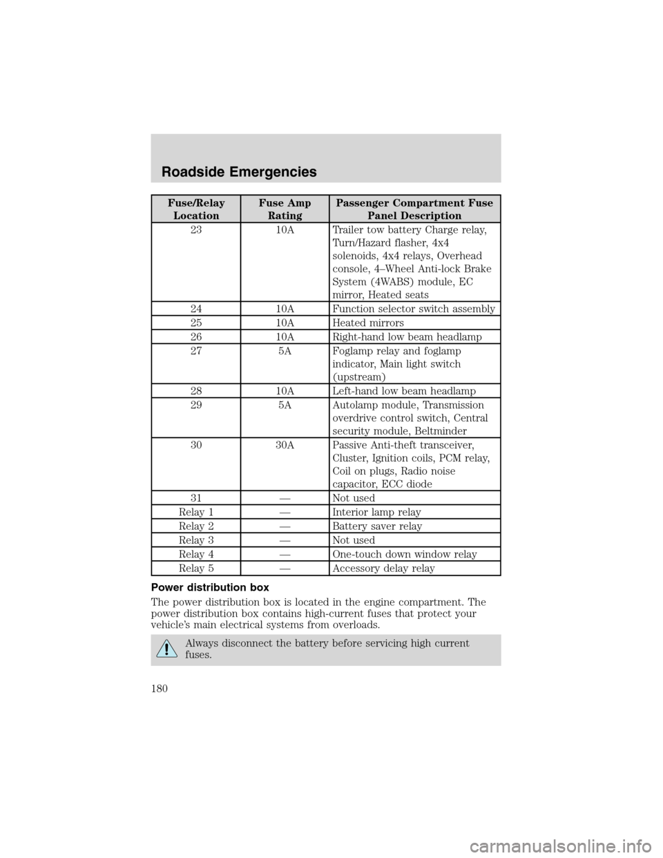
The fuses are coded as follows.
Fuse/Relay
LocationFuse Amp
RatingPassenger Compartment Fuse
Panel Description
1 15A Audio
2 5A Powertrain Control Module
(PCM), Cluster
3 20A Cigar lighter, Data link connector
4 5A Power mirror switch, Mirror turn
signal relays
5 15A Speed control module, Reverse
lamp, Climate mode switch,
Daytime Running Lamps (DRL)
relay, Digital Transmission Range
(DTR) sensor
6 5A Cluster, Brake shift interlock
solenoid, GEM
FUSE1 12 22
21323
617 27
718 28
819 29
930
20
31 21 11 10
RELAY
5 RELAY
4 RELAY
3 RELAY
2 RELAY
1
31424
41525
51626
Roadside Emergencies
178
Page 179 of 280
Fuse/Relay
LocationFuse Amp
RatingPassenger Compartment Fuse
Panel Description
7—Not used
8 5A Radio, Remote entry module,
GEM, In-vehicle entertainment
system (SuperCrew only)
9—Not used
10—Not used
11 30A Front washer pump relay, Wiper
run/park relay, Wiper HI/LO relay,
Windshield wiper motor
12—Not used
13 20A Stop lamp switch (Lamps),
Turn/Hazard flasher
14 15A Battery saver relay, Interior lamp
relay
15 5A Stop lamp switch (speed control,
brake shift interlock), GEM, Rear
Anti-lock Brake System (RABS)
module
16 20A Headlamps (hi beams), Cluster
(hi beam indicator)
17—Not used
18 5A Instrument illumination (dimmer
switch power)
19—Not used
20 5A Audio, GEM, PCM, Transmission
range sensor
21 15A DTR sensor, Clutch switch,
Starter relay, I/P fuse 20
22 10A Air bag module, Passenger air bag
deactivation module
Roadside Emergencies
179
Page 180 of 280
Fuse/Relay
LocationFuse Amp
RatingPassenger Compartment Fuse
Panel Description
23 10A Trailer tow battery Charge relay,
Turn/Hazard flasher, 4x4
solenoids, 4x4 relays, Overhead
console, 4–Wheel Anti-lock Brake
System (4WABS) module, EC
mirror, Heated seats
24 10A Function selector switch assembly
25 10A Heated mirrors
26 10A Right-hand low beam headlamp
27 5A Foglamp relay and foglamp
indicator, Main light switch
(upstream)
28 10A Left-hand low beam headlamp
29 5A Autolamp module, Transmission
overdrive control switch, Central
security module, Beltminder
30 30A Passive Anti-theft transceiver,
Cluster, Ignition coils, PCM relay,
Coil on plugs, Radio noise
capacitor, ECC diode
31—Not used
Relay 1—Interior lamp relay
Relay 2—Battery saver relay
Relay 3—Not used
Relay 4—One-touch down window relay
Relay 5—Accessory delay relay
Power distribution box
The power distribution box is located in the engine compartment. The
power distribution box contains high-current fuses that protect your
vehicle’s main electrical systems from overloads.
Always disconnect the battery before servicing high current
fuses.
Roadside Emergencies
180