radio LINCOLN MARK VIII 1998 Owners Manual
[x] Cancel search | Manufacturer: LINCOLN, Model Year: 1998, Model line: MARK VIII, Model: LINCOLN MARK VIII 1998Pages: 170, PDF Size: 1.37 MB
Page 38 of 170
moving. The readings that you get may not agree with temperatures
given on the radio due to differences in vehicle and station locations.
Operating tips
²In humid weather, select DEFbefore driving. This will prevent
your windshield from fogging. After a few minutes, select any desired
position.
²To prevent humidity buildup inside the vehicle, don't drive with the
climate control system in the OFF position.
²Don't put objects under the front seat that will interfere with the
airflow to the back seats.
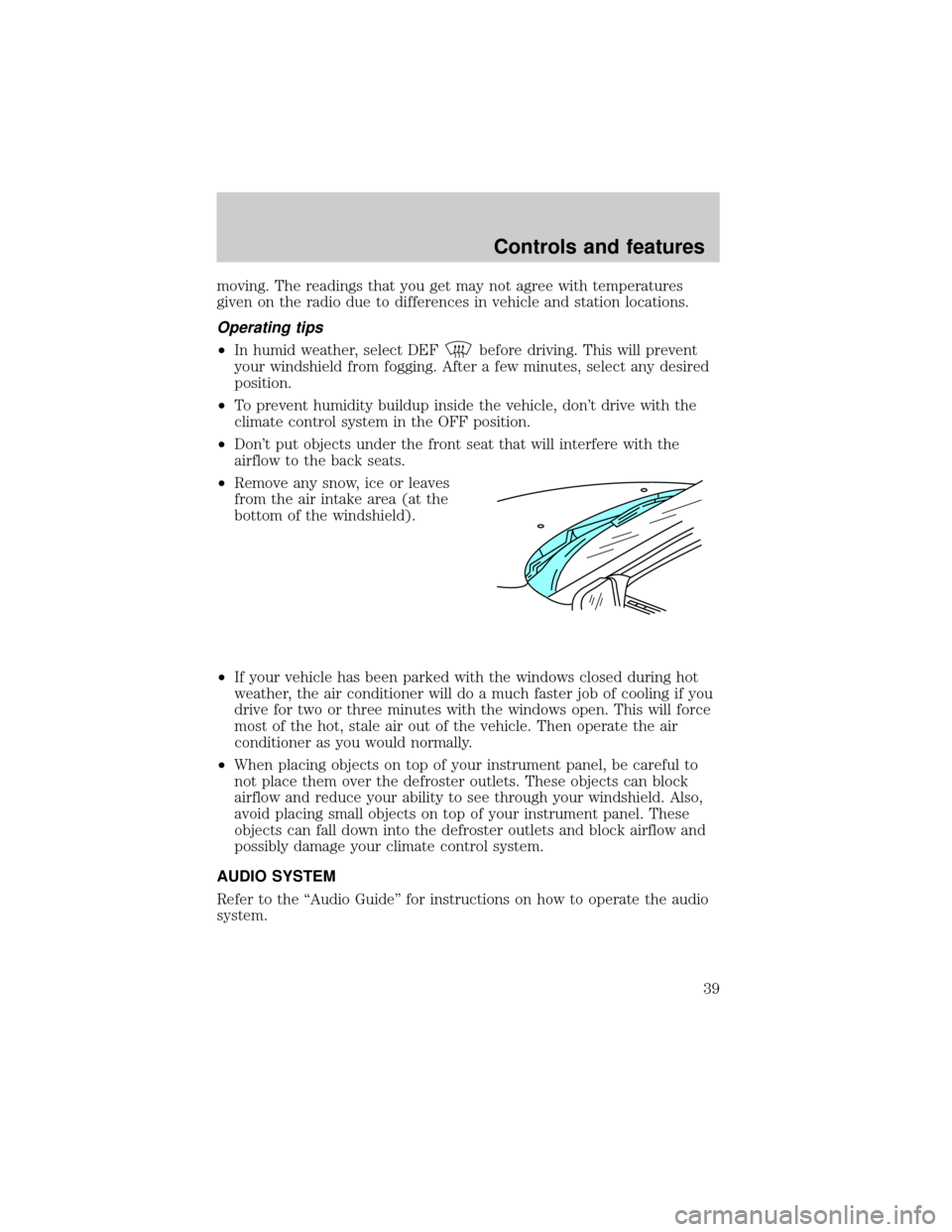
²Remove any snow, ice or leaves
from the air intake area (at the
bottom of the windshield).
²If your vehicle has been parked with the windows closed during hot
weather, the air conditioner will do a much faster job of cooling if you
drive for two or three minutes with the windows open. This will force
most of the hot, stale air out of the vehicle. Then operate the air
conditioner as you would normally.
²When placing objects on top of your instrument panel, be careful to
not place them over the defroster outlets. These objects can block
airflow and reduce your ability to see through your windshield. Also,
avoid placing small objects on top of your instrument panel. These
objects can fall down into the defroster outlets and block airflow and
possibly damage your climate control system.
AUDIO SYSTEM
Refer to the ªAudio Guideº for instructions on how to operate the audio
system.
Controls and features
39
Page 39 of 170
REAR WINDOW DEFROSTER
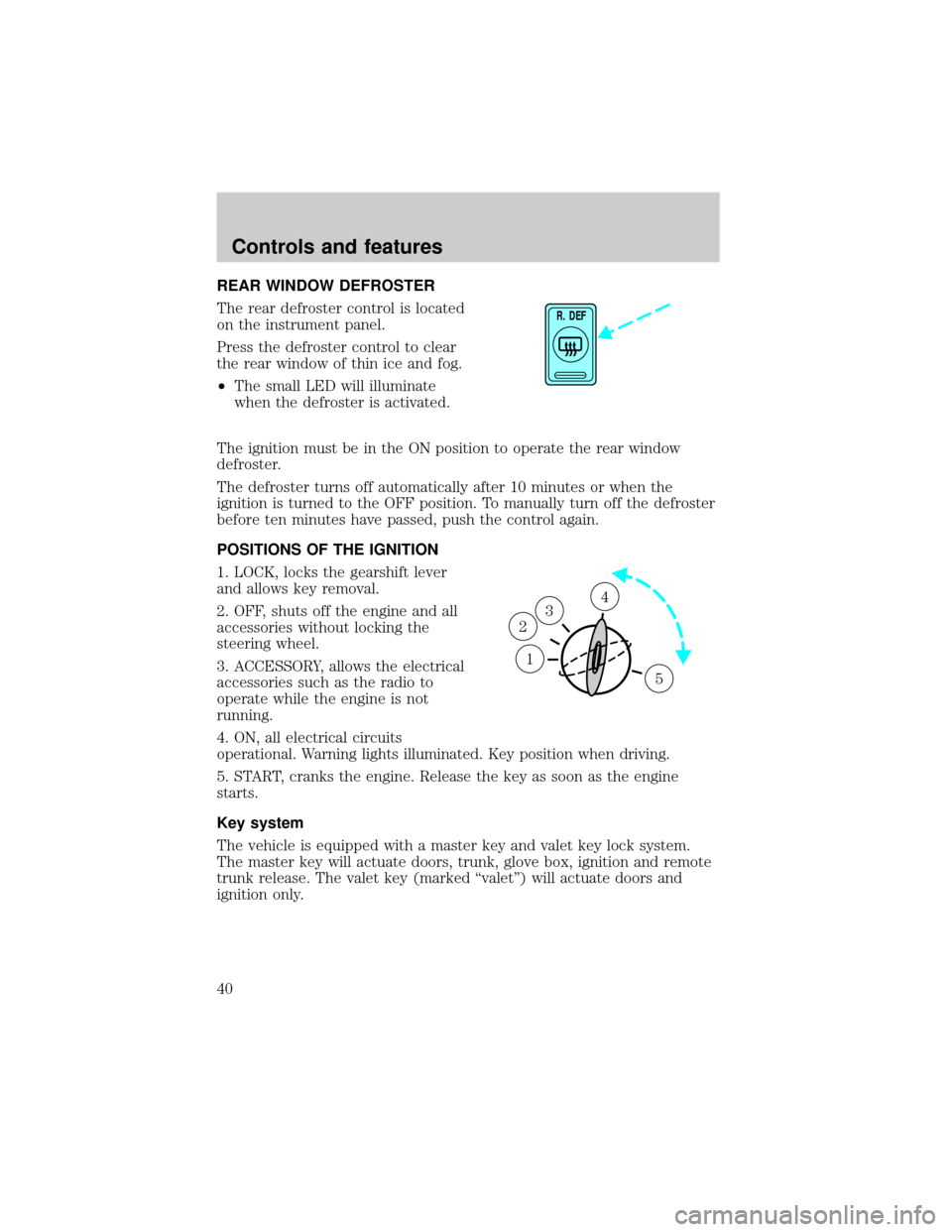
The rear defroster control is located
on the instrument panel.
Press the defroster control to clear
the rear window of thin ice and fog.
²The small LED will illuminate
when the defroster is activated.
The ignition must be in the ON position to operate the rear window
defroster.
The defroster turns off automatically after 10 minutes or when the
ignition is turned to the OFF position. To manually turn off the defroster
before ten minutes have passed, push the control again.
POSITIONS OF THE IGNITION
1. LOCK, locks the gearshift lever
and allows key removal.
2. OFF, shuts off the engine and all
accessories without locking the
steering wheel.
3. ACCESSORY, allows the electrical
accessories such as the radio to
operate while the engine is not
running.
4. ON, all electrical circuits
operational. Warning lights illuminated. Key position when driving.
5. START, cranks the engine. Release the key as soon as the engine
starts.
Key system
The vehicle is equipped with a master key and valet key lock system.
The master key will actuate doors, trunk, glove box, ignition and remote
trunk release. The valet key (marked ªvaletº) will actuate doors and
ignition only.
R. DEF
1
3
2
4
5
Controls and features
40
Page 46 of 170
To return to a previously set speed
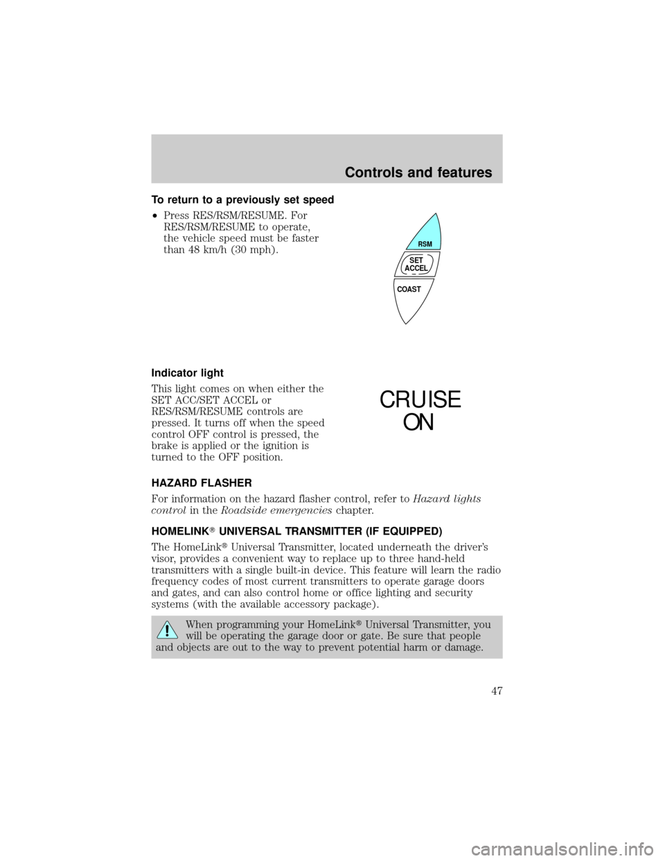
²Press RES/RSM/RESUME. For
RES/RSM/RESUME to operate,
the vehicle speed must be faster
than 48 km/h (30 mph).
Indicator light
This light comes on when either the
SET ACC/SET ACCEL or
RES/RSM/RESUME controls are
pressed. It turns off when the speed
control OFF control is pressed, the
brake is applied or the ignition is
turned to the OFF position.
HAZARD FLASHER
For information on the hazard flasher control, refer toHazard lights
controlin theRoadside emergencieschapter.
HOMELINKTUNIVERSAL TRANSMITTER (IF EQUIPPED)
The HomeLinktUniversal Transmitter, located underneath the driver's
visor, provides a convenient way to replace up to three hand-held
transmitters with a single built-in device. This feature will learn the radio
frequency codes of most current transmitters to operate garage doors
and gates, and can also control home or office lighting and security
systems (with the available accessory package).
When programming your HomeLinktUniversal Transmitter, you
will be operating the garage door or gate. Be sure that people
and objects are out to the way to prevent potential harm or damage.
COAST
RSM
SET
ACCEL
CRUISE
ON
Controls and features
47
Page 87 of 170
PREPARING TO START YOUR VEHICLE
Engine starting is controlled by the ignition system. This system meets
all Canadian Interference-Causing Equipment standard requirements
regulating the impulse electrical field strength of radio noise.
When starting a fuel-injected engine, avoid pressing the accelerator
before or during starting. Only use the accelerator when you have
difficulty starting the engine. For more information on starting the
vehicle, refer toStarting the enginein this chapter.
Extended idling at high engine speeds can produce very high
temperatures in the engine and exhaust system, creating the risk
of fire or other damage.
Do not park, idle, or drive your vehicle in dry grass or other dry
ground cover. The emission system heats up the engine
compartment and exhaust system, which can start a fire.
Do not start your vehicle in a closed garage or in other enclosed
areas. Exhaust fumes can be toxic. Always open the garage door
before you start the engine. SeeGuarding against exhaust fumesin
this chapter for more instructions.
If you smell exhaust fumes inside your vehicle, have your dealer
inspect your vehicle immediately. Do not drive if you smell
exhaust fumes.
Important safety precautions
A computer system controls the engine's idle revolutions per minute
(RPM). When the engine starts, the idle RPM runs faster to warm the
engine. If the engine idle speed does not slow down automatically, have
the vehicle checked. Do not allow the vehicle to idle for more than ten
minutes.
Starting
88
Page 109 of 170

To remove a fuse use the fuse puller tool provided on the fuse panel
cover.
The fuses are coded as follows.
Fuse/Relay
LocationFuse Amp
RatingDescription
1 10A Steering Column/Ignition/Lighting Module
(Brake Lamps, Climate Control Blower
Motor, Hazard Lamps, Speed Control)
2 10A Radio, Cellular Phone
3 Ð Not Used
4 10A Radio, Cellular Phone, Message Center,
Compass, Day/Night Mirror, Passenger Seat
Module
10 A
10 A10 A
15 A
15 A10 A
30 A
20 A10 A
10 A
10 A
10 A10A
10A
10A
10 A
10 A10 A
15 A 10 A
14523
7 6101189
13 12 16 1714 15
19 18 22 2320 21
25 24 28 2926 27
31 30 34 3532 33
37 36 40 4138 39 30 A
10 A
15 A
15 A
10 A10 A
10 A 10 A
Roadside emergencies
110
Page 110 of 170

Fuse/Relay
LocationFuse Amp
RatingDescription
5 10A Day/Night Sensor, Cluster (Oil Pressure,
Brake Warning, Speed Control), I/P
Warning Indicator Display, Steering
Column/Ignition/Lighting Module (Logic
Input)
6 10A Starter Motor Relay
7 15A Steering Column/Ignition/Lighting Module
(Left Turn Lamps)
8 Ð Not Used
9 10A Blower Motor Relay, Electronic Automatic
Temperature Control Module
10 30A Windshield Wipers
11 10A Coil Drivers, Radio Noise Capacitors, PCM
Relay
12 10A Passenger's Power and Heated Seats
13 15A Steering Column/Ignition/Lighting Module
(Right Turn Lamps)
14 30A Cigar Lighter, Cellular Phone, Power Point
15 10A Air Bag Diagnostic Monitor
16 20A Moonroof
17 10A Instrument Cluster (Charging Indicator)
18 Ð Not Used
19 10A Steering Column/Ignition/Lighting Module
(Left Low-Beam Headlamp)
20 10A Message Center, Instrument Cluster,
Electronic Automatic Temperature Control
Module
21 10A EVAC/Fill Connector, Anti-Lock Brake
Control Module
22 Ð Not Used
23 Ð Not Used
24 Ð Not Used
Roadside emergencies
111
Page 112 of 170
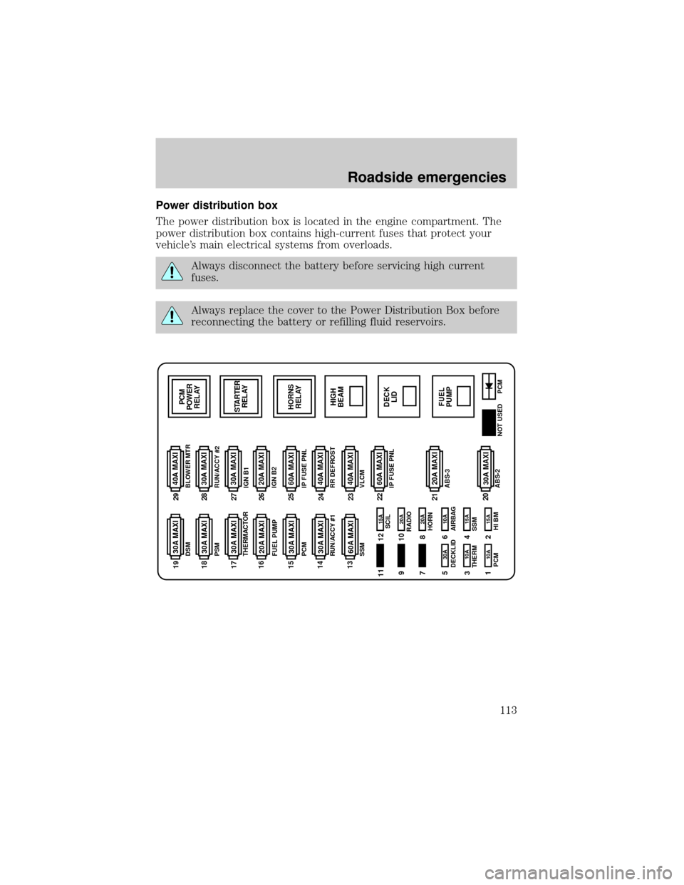
Power distribution box
The power distribution box is located in the engine compartment. The
power distribution box contains high-current fuses that protect your
vehicle's main electrical systems from overloads.
Always disconnect the battery before servicing high current
fuses.
Always replace the cover to the Power Distribution Box before
reconnecting the battery or refilling fluid reservoirs.
30A MAXI 20A MAXI 40A MAXI
PCM
POWER
RELAY
STARTER
RELAY
HORNS
RELAY
HIGH
BEAM
FUEL
PUMPDECK
LID 30A MAXI
30A MAXI
30A MAXI
30A MAXI
30A MAXI
20A MAXI
20A MAXI
60A MAXI
30A MAXI
40A MAXI
30A MAXI
40A MAXI
60A MAXI 60A MAXI
15A 15A 10A
10A 10A 30A20A 20A 15A
PCM
PCM HI BM
NOT USED SCIL
RADIO
HORN
AIRBAG DECKLID
SSM THERMDSM
PSM
THERMACTOR
FUEL PUMP
PCM
RUN/ACCY #1
SSMBLOWER MTR
RUN/ACCY #2
IGN B1
IGN B2
IP FUSE PNL
RR DEFROST
VLCM
IP FUSE PNL
ABS-3
ABS-21122 23 24 25 26 27 28 29 19
18
17
16
15
14
13
21
20 9
7
5
3
112
10
8
6
4
2
Roadside emergencies
113
Page 113 of 170

The high-current fuses are coded as follows.
Fuse/Relay
LocationFuse Amp
RatingDescription
1 10A* Powertrain Control Module (Keep-Alive
Memory)
2 15A* High Beam Relay, Daytime Running Lamps
Module
3 10A* Powertrain Control Module (EAM Pump
Motor-Monitor)
4 15A* Air Suspension, Electronically Variable
Orifice Power Steering
5 30A* Trunk Lid Relay, Fuel Filler Door Release
6 10A* Air Bag Module
7 Ð Not Used
8 20A* Horn Relay
9 Ð Not Used
10 20A* Radio Amplifier, CD Changer
11 Ð Not Used
12 15A* Steering Column/Ignition/Lighting Module
(Tilt/Telescoping Steering Column Motors,
Mirror Lamps, Brake Shift Interlock, High
Beam Indicator, Anti-Theft Indicator)
13 60A** Air Suspension
14 30A** Delayed Accessory Power Relay #1, I/P
Fuses (4, 10, 16)
15 30A** Powertrain Control Module, PCM Power
Relay, Engine Compartment Fuse 1
16 20A** Fuel Pump Relay, Fuel Pump Module
17 30A** Electronic Air Management, Engine
Compartment Fuse 3
18 30A** Passenger Seat Module, Passenger Lumbar,
I/P Fuse 12
19 30A** Driver Seat Module, Driver Lumbar, I/P
Fuse 35
Roadside emergencies
114
Page 135 of 170
3. The relearning process will automatically complete as you drive the
vehicle.
²If you do not allow the engine to relearn its idle, the idle quality of
your vehicle may be adversely affected until the idle is eventually
relearned.
²If the battery has been disconnected or a new battery has been
installed, the clock and the preset radio stations must be reset once
the battery is reconnected.
²Always dispose of automotive
batteries in a responsible manner.
Follow your community's
standards for disposal. Call your
local recycling center to find out
more about recycling automotive
batteries.
WINDSHIELD WIPER BLADES
Check the wiper blades at least twice a year or when they seem less
effective. Substances such as tree sap and some hot wax treatments used
by commercial car washes reduce the effectiveness of wiper blades.
Checking the wiper blades
If the wiper blades do not wipe properly, clean both the windshield and
wiper blades using undiluted windshield wiper solution or a mild
detergent. Rinse thoroughly with clean water. To avoid damaging the
blades, do not use fuel, kerosene, paint thinner or other solvents.
Changing the wiper blades
When replacing wiper blade assemblies, always use a Motorcraft part or
equivalent. To make replacing the wipers easy, turn the ignition to ACC,
then turn the wipers on. When the wipers reach the vertical position,
turn the ignition to LOCK.
Maintenance and care
136