lock LINCOLN MKT 2018 Manual Online
[x] Cancel search | Manufacturer: LINCOLN, Model Year: 2018, Model line: MKT, Model: LINCOLN MKT 2018Pages: 564, PDF Size: 4.66 MB
Page 271 of 564
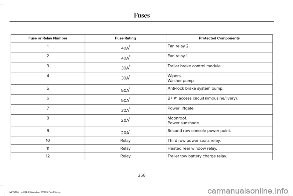
Protected Components
Fuse Rating
Fuse or Relay Number
Fan relay 2.
40A 1
1
Fan relay 1.
40A 1
2
Trailer brake control module.
30A 1
3
Wipers.
30A 1
4
Washer pump.
Anti-lock brake system pump.
50A 1
5
B+ #1 access circuit (limousine/livery).
50A 1
6
Power liftgate.
30A 1
7
Moonroof.
20A 1
8
Power sunshade.
Second row console power point.
20A 1
9
Third row power seats relay.
Relay
10
Heated rear window relay.
Relay
11
Trailer tow battery charge relay.
Relay
12
268
MKT (TP4) , enUSA, Edition date: 201703, First Printing Fuses
Page 274 of 564
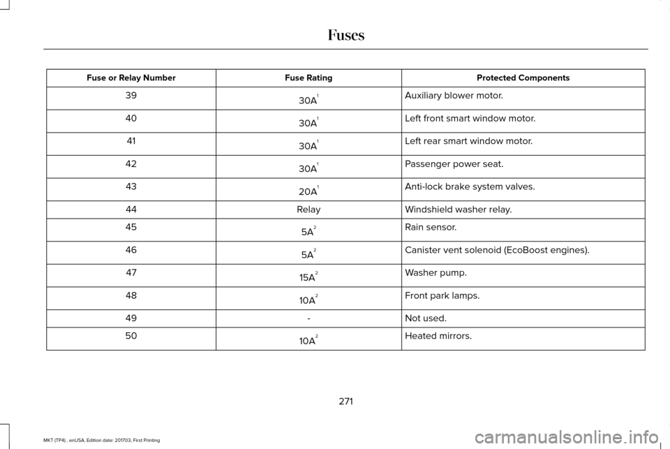
Protected Components
Fuse Rating
Fuse or Relay Number
Auxiliary blower motor.
30A 1
39
Left front smart window motor.
30A 1
40
Left rear smart window motor.
30A 1
41
Passenger power seat.
30A 1
42
Anti-lock brake system valves.
20A 1
43
Windshield washer relay.
Relay
44
Rain sensor.
5A 2
45
Canister vent solenoid (EcoBoost engines).
5A 2
46
Washer pump.
15A 2
47
Front park lamps.
10A 2
48
Not used.
-
49
Heated mirrors.
10A 2
50
271
MKT (TP4) , enUSA, Edition date: 201703, First Printing Fuses
Page 278 of 564
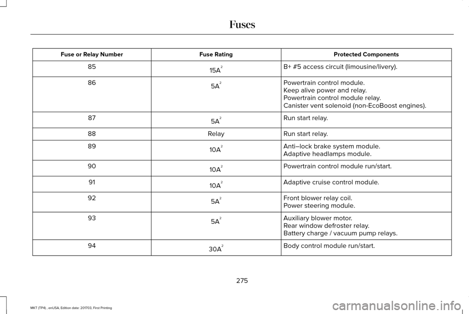
Protected Components
Fuse Rating
Fuse or Relay Number
B+ #5 access circuit (limousine/livery).
15A 2
85
Powertrain control module.
5A 2
86
Keep alive power and relay.
Powertrain control module relay.
Canister vent solenoid (non-EcoBoost engines).
Run start relay.
5A 2
87
Run start relay.
Relay
88
Anti–lock brake system module.
10A 2
89
Adaptive headlamps module.
Powertrain control module run/start.
10A 2
90
Adaptive cruise control module.
10A 2
91
Front blower relay coil.
5A 2
92
Power steering module.
Auxiliary blower motor.
5A 2
93
Rear window defroster relay.
Battery charge / vacuum pump relays.
Body control module run/start.
30A 2
94
275
MKT (TP4) , enUSA, Edition date: 201703, First Printing Fuses
Page 282 of 564
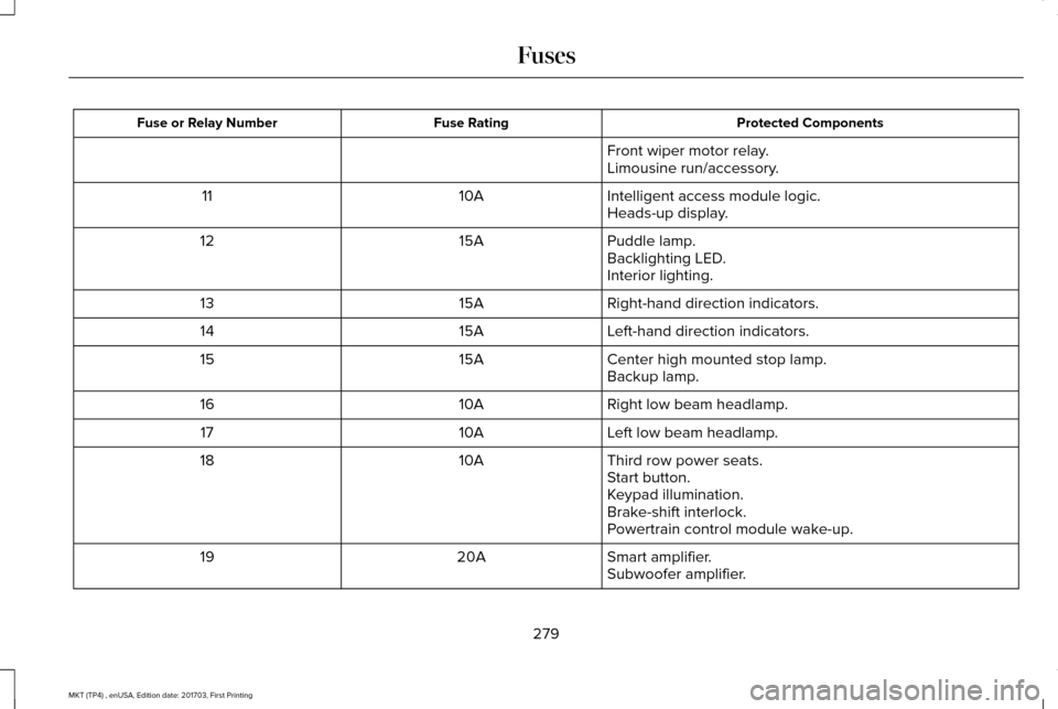
Protected Components
Fuse Rating
Fuse or Relay Number
Front wiper motor relay.
Limousine run/accessory.
Intelligent access module logic.
10A
11
Heads-up display.
Puddle lamp.
15A
12
Backlighting LED.
Interior lighting.
Right-hand direction indicators.
15A
13
Left-hand direction indicators.
15A
14
Center high mounted stop lamp.
15A
15
Backup lamp.
Right low beam headlamp.
10A
16
Left low beam headlamp.
10A
17
Third row power seats.
10A
18
Start button.
Keypad illumination.
Brake-shift interlock.
Powertrain control module wake-up.
Smart amplifier.
20A
19
Subwoofer amplifier.
279
MKT (TP4) , enUSA, Edition date: 201703, First Printing Fuses
Page 284 of 564
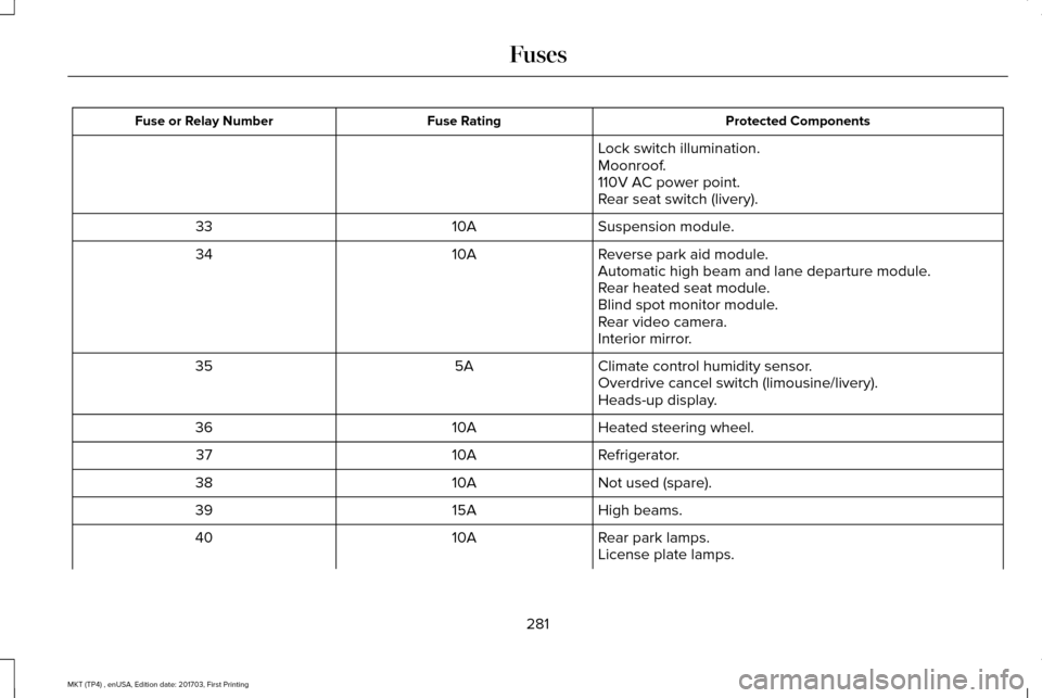
Protected Components
Fuse Rating
Fuse or Relay Number
Lock switch illumination.
Moonroof.
110V AC power point.
Rear seat switch (livery).
Suspension module.
10A
33
Reverse park aid module.
10A
34
Automatic high beam and lane departure module.
Rear heated seat module.
Blind spot monitor module.
Rear video camera.
Interior mirror.
Climate control humidity sensor.
5A
35
Overdrive cancel switch (limousine/livery).
Heads-up display.
Heated steering wheel.
10A
36
Refrigerator.
10A
37
Not used (spare).
10A
38
High beams.
15A
39
Rear park lamps.
10A
40
License plate lamps.
281
MKT (TP4) , enUSA, Edition date: 201703, First Printing Fuses
Page 289 of 564
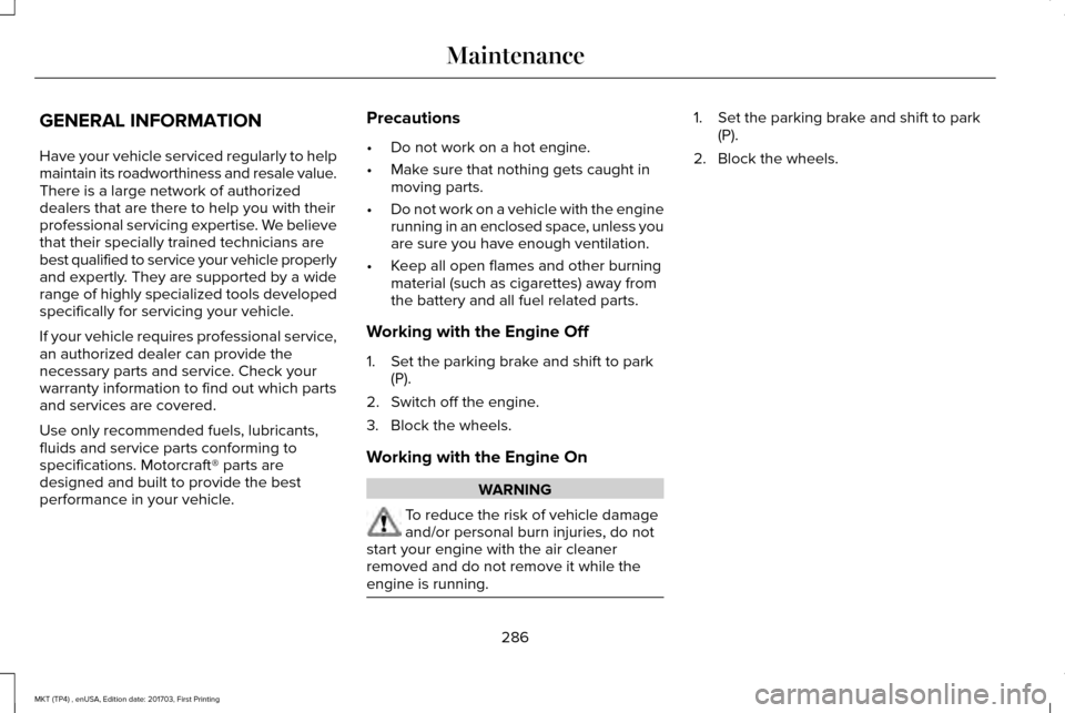
GENERAL INFORMATION
Have your vehicle serviced regularly to help
maintain its roadworthiness and resale value.
There is a large network of authorized
dealers that are there to help you with their
professional servicing expertise. We believe
that their specially trained technicians are
best qualified to service your vehicle properly
and expertly. They are supported by a wide
range of highly specialized tools developed
specifically for servicing your vehicle.
If your vehicle requires professional service,
an authorized dealer can provide the
necessary parts and service. Check your
warranty information to find out which parts
and services are covered.
Use only recommended fuels, lubricants,
fluids and service parts conforming to
specifications. Motorcraft® parts are
designed and built to provide the best
performance in your vehicle.
Precautions
•
Do not work on a hot engine.
• Make sure that nothing gets caught in
moving parts.
• Do not work on a vehicle with the engine
running in an enclosed space, unless you
are sure you have enough ventilation.
• Keep all open flames and other burning
material (such as cigarettes) away from
the battery and all fuel related parts.
Working with the Engine Off
1. Set the parking brake and shift to park (P).
2. Switch off the engine.
3. Block the wheels.
Working with the Engine On WARNING
To reduce the risk of vehicle damage
and/or personal burn injuries, do not
start your engine with the air cleaner
removed and do not remove it while the
engine is running. 1. Set the parking brake and shift to park
(P).
2. Block the wheels.
286
MKT (TP4) , enUSA, Edition date: 201703, First Printing Maintenance
Page 295 of 564
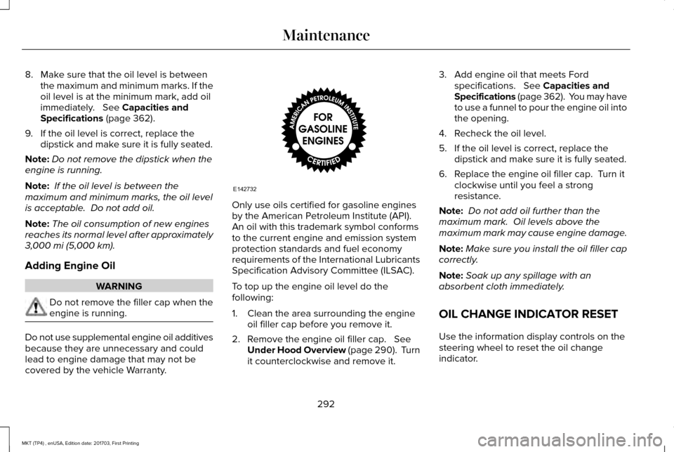
8. Make sure that the oil level is between
the maximum and minimum marks. If the
oil level is at the minimum mark, add oil
immediately. See Capacities and
Specifications (page 362).
9. If the oil level is correct, replace the dipstick and make sure it is fully seated.
Note: Do not remove the dipstick when the
engine is running.
Note: If the oil level is between the
maximum and minimum marks, the oil level
is acceptable. Do not add oil.
Note: The oil consumption of new engines
reaches its normal level after approximately
3,000 mi (5,000 km)
.
Adding Engine Oil WARNING
Do not remove the filler cap when the
engine is running.
Do not use supplemental engine oil additives
because they are unnecessary and could
lead to engine damage that may not be
covered by the vehicle Warranty. Only use oils certified for gasoline engines
by the American Petroleum Institute (API).
An oil with this trademark symbol conforms
to the current engine and emission system
protection standards and fuel economy
requirements of the International Lubricants
Specification Advisory Committee (ILSAC).
To top up the engine oil level do the
following:
1. Clean the area surrounding the engine
oil filler cap before you remove it.
2. Remove the engine oil filler cap.
See
Under Hood Overview (page 290). Turn
it counterclockwise and remove it. 3. Add engine oil that meets Ford
specifications.
See Capacities and
Specifications (page 362). You may have
to use a funnel to pour the engine oil into
the opening.
4. Recheck the oil level.
5. If the oil level is correct, replace the dipstick and make sure it is fully seated.
6. Replace the engine oil filler cap. Turn it clockwise until you feel a strong
resistance.
Note: Do not add oil further than the
maximum mark. Oil levels above the
maximum mark may cause engine damage.
Note: Make sure you install the oil filler cap
correctly.
Note: Soak up any spillage with an
absorbent cloth immediately.
OIL CHANGE INDICATOR RESET
Use the information display controls on the
steering wheel to reset the oil change
indicator.
292
MKT (TP4) , enUSA, Edition date: 201703, First Printing MaintenanceE142732
Page 297 of 564
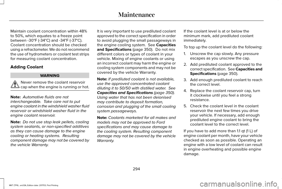
Maintain coolant concentration within 48%
to 50%, which equates to a freeze point
between -30°F (-34°C) and -34°F (-37°C).
Coolant concentration should be checked
using a refractometer. We do not recommend
the use of hydrometers or coolant test strips
for measuring coolant concentration.
Adding Coolant
WARNING
Never remove the coolant reservoir
cap when the engine is running or hot.
Note:
Automotive fluids are not
interchangeable. Take care not to put
engine coolant in the windshield washer fluid
reservoir or windshield washer fluid in the
engine coolant reservoir.
Note: Do not use stop leak pellets, cooling
system sealants, or non-specified additives
as they can cause damage to the engine
cooling or heating systems. Resulting
component damage may not be covered by
the vehicle Warranty. It is very important to use prediluted coolant
approved to the correct specification in order
to avoid plugging the small passageways in
the engine cooling system. See Capacities
and Specifications (page 350). Do not mix
different colors or types of coolant in your
vehicle. Mixing of engine coolants or using
an incorrect coolant may harm the engine or
cooling system components and may not be
covered by the vehicle Warranty.
Note: If prediluted coolant is not available,
use the approved concentrated coolant
diluting it to 50/50 with distilled water.
See
Capacities and Specifications (page 350).
Using water that has not been deionised
may contribute to deposit formation,
corrosion and plugging of the small cooling
system passageways.
Note: Coolants marketed for all makes and
models may not be approved to Ford
specifications and may cause damage to
the cooling system. Resulting component
damage may not be covered by the vehicle
Warranty. If the coolant level is at or below the
minimum mark, add prediluted coolant
immediately.
To top up the coolant level do the following:
1. Unscrew the cap slowly. Any pressure
escapes as you unscrew the cap.
2. Add prediluted coolant approved to the correct specification. See Capacities and
Specifications
(page 350).
3. Add enough prediluted coolant to reach
the correct level.
4. Replace the coolant reservoir cap, turn it clockwise until you feel a strong
resistance.
5. Check the coolant level in the coolant reservoir the next few times you drive
your vehicle. If necessary, add enough
prediluted engine coolant to bring the
coolant level to the correct level.
If you have to add more than
1.1 qt (1 L) of
engine coolant per month, have your vehicle
checked as soon as possible. Operating an
engine with a low level of coolant can result
in engine overheating and possible engine
damage.
294
MKT (TP4) , enUSA, Edition date: 201703, First Printing Maintenance
Page 301 of 564
2. Leave the engine running until the
coolant temperature gauge needle
returns to the normal position. After
several minutes, if the temperature does
not drop, follow the remaining steps.
3. Switch the engine off and wait for it to cool. Check the coolant level.
4. If the coolant level is at or below the minimum mark, add prediluted coolant
immediately.
5. If the coolant level is normal, restart the engine and continue.
AUTOMATIC TRANSMISSION
FLUID CHECK WARNING
Do not use supplemental transmission
fluid additives, treatments or cleaning
agents. The use of these materials may affect
transmission operation and result in damage
to internal transmission components. The transmission does not consume fluid.
However, if the transmission slips or shifts
slowly you should check the fluid level. If you
notice a sign of leaking fluid, contact an
authorized dealer.
Checking the Transmission Fluid Level
WARNING
The dipstick and surrounding
components are hot. Use gloves when
moving components and checking the
transmission fluid level. Failure to follow this
warning could result in serious personal
injury. Only check the transmission fluid level when
the engine is at normal operating
temperature 179°F (82°C)-199°F (93°C).
Normal operating temperature is reached
after driving approximately
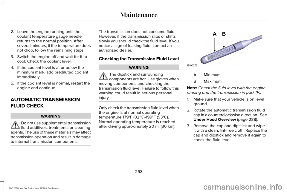
20 mi (30 km). Minimum.
A
Maximum.
B
Note: Check the fluid level with the engine
running and the transmission in park (P).
1. Make sure that your vehicle is on level ground.
2. Rotate the automatic transmission fluid cap in a counterclockwise direction. See
Under Hood Overview
(page 288).
3. Remove the cap and dipstick and wipe it with a clean, lint-free cloth. Replace the
cap and dipstick and remove it again to
check the fluid level.
298
MKT (TP4) , enUSA, Edition date: 201703, First Printing MaintenanceE190273
AB
Page 302 of 564
4.
Make sure that the fluid level is between
the MIN and the MAX marks. If the fluid
level is at the MIN mark, add fluid
immediately. See Adding Transmission
Fluid.
5. Replace the automatic transmission fluid
cap and dipstick. Turn it clockwise until
you feel a strong resistance.
Low Fluid Level
If the fluid level is within the minimum range
(below point A) add the correct specification
fluid to be within the hash mark area.
See
Capacities and Specifications (page 356).
Note: If the fluid level is below the minimum
range do not drive your vehicle. A low fluid
level can damage the transmission.
Correct Fluid Level
If the fluid level is within the hash mark area
(between points A and B) do not add any
fluid. High Fluid Level
If the fluid level is above the maximum range
(above point B) fluid may need to be
removed. High fluid levels may be caused
by a overheating condition. If you have
operated your vehicle at high speeds, towing
a trailer or in city traffic during hot weather,
allow your vehicle to cool for a minimum of
30 minutes before rechecking the level.
Note:
An overfill condition can damage the
transmission.
Adding Transmission Fluid *
1. Rotate the automatic transmission fluid cap in a counterclockwise direction.
2. Remove the cap and dipstick and wipe it with a clean, lint-free cloth.
3. Add fluid that meets the Ford specifications.
See Capacities and
Specifications (page 356). Pour the fluid
directly into the automatic transmission
fluid cap and dipstick hole.
4. Replace the cap and dipstick and remove
it again to check the fluid level. 5.
Make sure that the fluid level is between
the MIN and the MAX marks.
6. Replace the automatic transmission fluid
cap and dipstick. Turn it clockwise until
you feel a strong resistance.
* Vehicles With EcoBoost Engine WARNING
Do not run the engine with the air filter
disconnected.
1. Loosen the clamp holding the air filter
assembly to the rubber hose.
2. Remove the air filter assembly securing bolts.
3. Lift the air filter assembly to disengage the locating pins.
4. Rotate the air filter assembly slightly in a
counterclockwise direction.
5. Check the transmission fluid level.
6. Install the air filter assembly in reverse order. Tighten the air filter assembly
securing bolts until you feel a strong
resistance.
299
MKT (TP4) , enUSA, Edition date: 201703, First Printing Maintenance