sensor LINCOLN NAVIGATOR 2017 Owner's Guide
[x] Cancel search | Manufacturer: LINCOLN, Model Year: 2017, Model line: NAVIGATOR, Model: LINCOLN NAVIGATOR 2017Pages: 532, PDF Size: 3.9 MB
Page 314 of 532
If you feel a sudden vibration or ride
disturbance while driving, or you suspect
your tire or vehicle has been damaged,
immediately reduce your speed. Drive
with caution until you can safely pull off
the road. Stop and inspect the tires for
damage. If a tire is under-inflated or
damaged, deflate it, remove wheel and
replace it with your spare tire and wheel.
If you cannot detect a cause, have the
vehicle towed to the nearest repair
facility or tire dealer to have the vehicle
inspected.
Tire and Wheel Alignment
A bad jolt from hitting a curb or pothole
can cause the front end of your vehicle
to become misaligned or cause damage
to your tires. If your vehicle seems to
pull to one side when you’re driving, the
wheels may be out of alignment. Have
an authorized dealer check the wheel
alignment periodically.
Wheel misalignment in the front or the
rear can cause uneven and rapid
treadwear of your tires and should be
corrected by an authorized dealer.
Front-wheel drive vehicles and those
with an independent rear suspension
may require alignment of all four wheels.
The tires should also be balanced
periodically. An unbalanced tire and
wheel assembly may result in irregular
tire wear.
Tire Rotation
WARNING
If the tire label shows different tire
pressures for the front and rear
tires and the vehicle has a tire pressure
monitoring system, then you need to
update the settings for the system
sensors. Always perform the system
reset procedure after tire rotation. If you
do not reset the system, it may not
provide a low tire pressure warning
when necessary. Note:
If your tires show uneven wear
ask an authorized dealer to check for
and correct any wheel misalignment,
tire imbalance or mechanical problem
involved before tire rotation.
Note: Your vehicle may be equipped
with a dissimilar spare wheel and tire
assembly. A dissimilar spare wheel and
tire assembly is defined as a spare
wheel and tire assembly that is different
in brand, size or appearance from the
road tires and wheels. If you have a
dissimilar spare wheel and tire assembly
it is intended for temporary use only and
should not be used in a tire rotation.
Note: After having your tires rotated,
inflation pressure must be checked and
adjusted to the vehicle requirements.
Rotating your tires at the recommended
interval (as indicated in the Scheduled
Maintenance chapter) will help your tires
wear more evenly, providing better tire
performance and longer tire life.
Rear-wheel drive vehicles and
four-wheel drive vehicles (front tires at
left of diagram)
311
Navigator (TB5) Canada/United States of America, enUSA, First Printing Wheels and Tires
Page 317 of 532
Please note that the TPMS is not a substitute
for proper tire maintenance, and it is the
driver’
s responsibility to maintain correct tire
pressure, even if under-inflation has not
reached the level to trigger illumination of
the TPMS low tire pressure telltale.
Your vehicle has also been equipped with a
TPMS malfunction indicator to indicate when
the system is not operating properly. The
TPMS malfunction indicator is combined with
the low tire pressure telltale. When the
system detects a malfunction, the telltale will
flash for approximately one minute and then
remain continuously illuminated. This
sequence will continue upon subsequent
vehicle start-ups as long as the malfunction
exists.
When the malfunction indicator is illuminated,
the system may not be able to detect or
signal low tire pressure as intended. TPMS
malfunctions may occur for a variety of
reasons, including the installation of
replacement or alternate tires or wheels on
the vehicle that prevent the TPMS from functioning properly. Always check the TPMS
malfunction telltale after replacing one or
more tires or wheels on your vehicle to
ensure that the replacement or alternate tires
and wheels allow the TPMS to continue to
function properly.
The tire pressure monitoring system
complies with part 15 of the FCC rules and
with RSS-210 of Industry Canada. Operation
is subject to the following two conditions: (1)
This device may not cause harmful
interference, and (2) This device must accept
any interference received, including
interference that may cause undesired
operation.
This device complies with part 15 of the FCC
Rules and with Licence exempt RSS
Standards of Industry Canada. Operation is
subject to the following two conditions:
•
This device may not cause harmful
interference.
• This device must accept any interference
received, including interference that may
cause undesired operation. Changing Tires With a Tire Pressure
Monitoring System
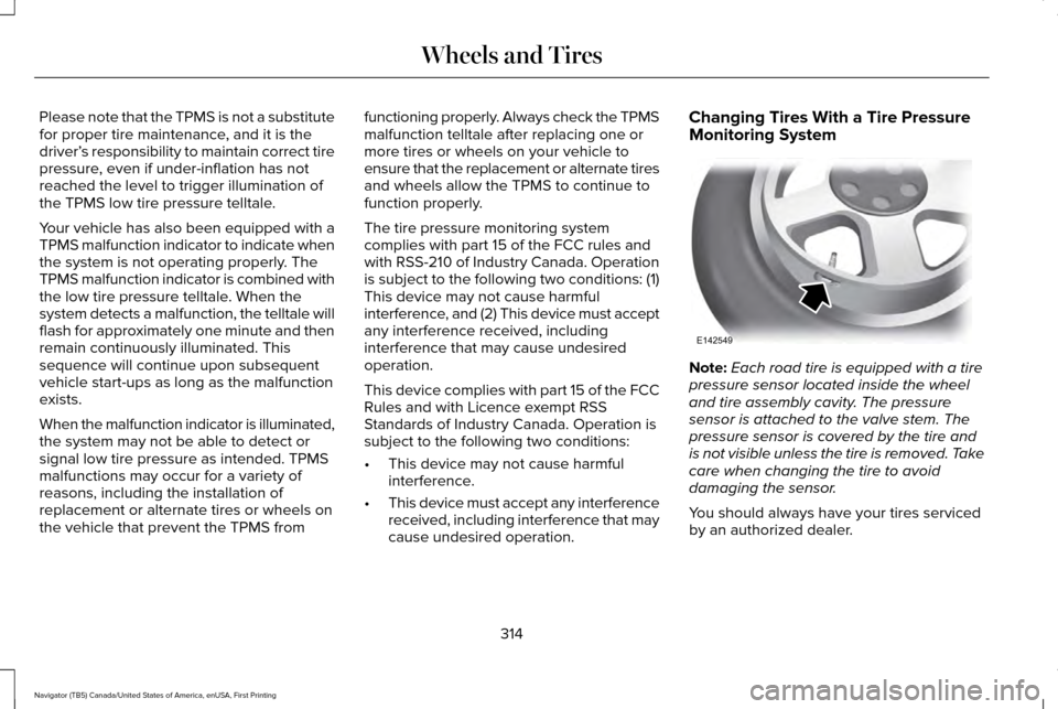
Note:
Each road tire is equipped with a tire
pressure sensor located inside the wheel
and tire assembly cavity. The pressure
sensor is attached to the valve stem. The
pressure sensor is covered by the tire and
is not visible unless the tire is removed. Take
care when changing the tire to avoid
damaging the sensor.
You should always have your tires serviced
by an authorized dealer.
314
Navigator (TB5) Canada/United States of America, enUSA, First Printing Wheels and TiresE142549
Page 320 of 532
Customer action required
Possible cause
Low tire pressure warning light
On vehicles with different front and rear tire pressures, the system
must be retrained following every tire rotation. See Tire Care
(page 298).
Tire rotation without sensor training
Repair the damaged road wheel and tire assembly and reinstall
it on the vehicle to restore system function. For a description on
how the system functions, see
When your temporary spare tire
is installed in this section.
Spare tire in use
Flashing warning light
If the tires are properly inflated and the spare tire is not in use but
the light remains on, contact your authorized dealer as soon as
possible.
Tire pressure monitoring system
malfunction
When Inflating Your Tires
When putting air into your tires (such as at a
gas station or in your garage), the tire
pressure monitoring system may not respond
immediately to the air added to your tires.
It may take up to two minutes of driving over
20 mph (32 km/h) for the light to turn off after
you have filled your tires to the
recommended inflation pressure. How Temperature Affects Your Tire
Pressure
The tire pressure monitoring system monitors
tire pressure in each pneumatic tire. While
driving in a normal manner, a typical
passenger tire inflation pressure may
increase about 2 to 4 psi (14 to 28 kPa) from
a cold start situation. If the vehicle is
stationary overnight with the outside
temperature significantly lower than the
daytime temperature, the tire pressure may
decrease about 3 psi (21 kPa) for a drop of30°F (17°C) in ambient temperature. This
lower pressure value may be detected by
the tire pressure monitoring system as being
significantly lower than the recommended
inflation pressure and activate the system
warning light for low tire pressure.
317
Navigator (TB5) Canada/United States of America, enUSA, First Printing Wheels and Tires
Page 321 of 532
If the low tire pressure warning light is on,
visually check each tire to verify that no tire
is flat. If one or more tires are flat, repair as
necessary. Check the air pressure in the road
tires. If any tire is under-inflated, carefully
drive the vehicle to the nearest location
where air can be added to the tires. Inflate
all the tires to the recommended inflation
pressure.
Tire Pressure Monitoring System Reset
Procedure
WARNING
To determine the required pressure(s)
for your vehicle, see the Safety
Compliance Certification Label (on the door
hinge pillar, door-latch post or the door edge
that meets the door-latch post, next to the
driver seat) or the Tire Label on the B-Pillar
or the edge of the driver door. Note:
You need to perform the tire pressure
monitoring system reset procedure after
each tire rotation on vehicles that require
different recommended tire pressures in the
front tires as compared to the rear tires. Overview
To provide the vehicle's load carrying
capability, some vehicles require different
recommended tire pressures in the front tires
as compared to the rear tires. The tire
pressure monitoring system equipped on
these vehicles is designed to illuminate the
low tire pressure warning light at two
different pressures; one for the front tires
and one for the rear tires.
Since tires need to be rotated to provide
consistent performance and maximum tire
life, the tire pressure monitoring system
needs to know when the tires are rotated to
determine which set of tires are on the front
and which are on the rear. With this
information, the system can detect and
properly warn of low tire pressures.
System reset tips:
•
To reduce the chances of interference
from another vehicle, perform the system
reset procedure at least three feet (one
meter) away from another Ford Motor
Company vehicle undergoing the system
reset procedure at the same time.
• Do not wait more than two minutes
between resetting each tire sensor or the
system will time-out and the entire
procedure will have to be repeated on
all four wheels.
• A double horn will sound indicating the
need to repeat the procedure.
Performing the System Reset Procedure
Read the entire procedure before attempting.
1. Drive the vehicle above 20 mph (32 km/h) for at least two minutes, then park
in a safe location where you can easily
get to all four tires and have access to
an air pump.
2. Place the ignition in the off position and keep the key in the ignition.
3. Cycle the ignition to the on position with
the engine off.
318
Navigator (TB5) Canada/United States of America, enUSA, First Printing Wheels and Tires
Page 322 of 532
4.
Turn the hazard flashers on then off three
times. You must accomplish this within
10 seconds. If the reset mode has been
entered successfully, the horn will sound
once, the system indicator will flash and
a message is shown in the information
display. If this does not occur, please try
again starting at Step 2. If after repeated
attempts to enter the reset mode, the
horn does not sound, the system
indicator does not flash and no message
is shown in the information display, seek
service from your authorized dealer.
5. Train the tire pressure monitoring system
sensors in the tires using the following
system reset sequence starting with the
left front tire in the following clockwise
order: Left front (driver's side front tire),
Right front (passenger's side front tire),
Right rear (passenger's side rear tire), Left
rear (driver's side rear tire).
6. Remove the valve cap from the valve stem on the left front tire. Decrease the
air pressure until the horn sounds. Note:
The single horn chirp confirms that the
sensor identification code has been learned
by the module for this position. If a double
horn is heard, the reset procedure was
unsuccessful, and you must repeat it.
7. Remove the valve cap from the valve stem on the right front tire. Decrease the
air pressure until the horn sounds.
8. Remove the valve cap from the valve stem on the right rear tire. Decrease the
air pressure until the horn sounds.
9. Remove the valve cap from the valve stem on the left rear tire. Decrease the
air pressure until the horn sounds.
Training is complete after the horn
sounds for the last tire trained (driver's
side rear tire), the system indicator stops
flashing, and a message is shown in the
information display.
10. Turn the ignition off. If two short horn beeps are heard, the reset procedure
was unsuccessful and you must repeat
it. If after repeating the procedure and
two short beeps are heard when the
ignition is turned to off, seek assistance
from your authorized dealer. 11. Set all four tires to the recommended
air pressure as indicated on the Safety
Compliance Certification Label (affixed
to either the door hinge pillar,
door-latch post, or the door edge that
meets the door-latch post, next to the
driver's seating position) or Tire Label
located on the B-Pillar or the edge of
the driver's door.
CHANGING A ROAD WHEEL WARNINGS
The use of tire sealant may damage
your tire pressure monitoring system
and should only be used in roadside
emergencies. If you must use a sealant, the
Ford Tire Mobility Kit sealant should be used.
The tire pressure monitoring system sensor
and valve stem on the wheel must be
replaced by an authorized dealer after use
of the sealant. If the tire pressure monitor sensor
becomes damaged, it will no longer
function. See Tire Pressure Monitoring
System (page 313). 319
Navigator (TB5) Canada/United States of America, enUSA, First Printing Wheels and Tires
Page 323 of 532
Note:
The tire pressure monitoring system
indicator light will illuminate when the spare
tire is in use. To restore the full function of
the monitoring system, all road wheels
equipped with tire pressure monitoring
sensors must be mounted on this vehicle.
If you get a flat tire while driving, do not apply
the brake heavily. Instead, gradually
decrease your speed. Hold the steering
wheel firmly and slowly move to a safe place
on the side of the road.
Have a flat serviced by an authorized dealer
in order to prevent damage to the system
sensors See Tire Pressure Monitoring
System (page 313). Replace the spare tire
with a road tire as soon as possible. During
repairing or replacing of the flat tire, have
the authorized dealer inspect the system
sensor for damage.
Dissimilar Spare Wheel and Tire
Assembly Information WARNING
Failure to follow these guidelines could
result in an increased risk of loss of
vehicle control, injury or death. If you have a dissimilar spare wheel and tire,
then it is intended for temporary use only.
This means that if you need to use it, you
should replace it as soon as possible with a
road wheel and tire assembly that is the
same size and type as the road tires and
wheels that were originally provided by Ford.
If the dissimilar spare tire or wheel is
damaged, it should be replaced rather than
repaired.
A dissimilar spare wheel and tire assembly
is defined as a spare wheel and tire assembly
that is different in brand, size or appearance
from the road tires and wheels and can be
one of three types:
1. T-type mini-spare: This spare tire begins
with the letter T for tire size and may have
Temporary Use Only molded in the sidewall.
2.
Full-size dissimilar spare with label on
wheel: This spare tire has a label on the
wheel that states: THIS WHEEL AND TIRE
ASSEMBLY FOR TEMPORARY USE ONLY When driving with one of the dissimilar spare
tires listed above, do not:
•
Exceed
50 mph (80 km/h).
• Load the vehicle beyond maximum
vehicle load rating listed on the Safety
Compliance Label.
• Tow a trailer.
• Use snow chains on the end of the
vehicle with the dissimilar spare tire.
• Use more than one dissimilar spare tire
at a time.
• Use commercial car washing equipment.
• Try to repair the dissimilar spare tire.
Use of one of the dissimilar spare tires listed
above at any one wheel location can lead to
impairment of the following:
• Handling, stability and braking
performance.
• Comfort and noise.
• Ground clearance and parking at curbs.
• Winter weather driving capability.
• Wet weather driving capability.
• All-wheel driving capability.
320
Navigator (TB5) Canada/United States of America, enUSA, First Printing Wheels and Tires
Page 523 of 532
B
Battery
See: Changing the 12V Battery.......................275
Blind Spot Information System..................201
False Alerts..........................................................206
Switching the System Off and On.................206
System Errors......................................................206
System Limitations.............................................205
Using the System................................................201
Bonnet Lock See: Opening and Closing the Hood............262
Booster Seats
..................................................26
Types of Booster Seats.......................................26
Brake Fluid Check
........................................273
Brakes..............................................................182 General Information............................................182
Breaking-In.....................................................228
Bulb Specification Chart
..............................281
C
California Proposition 65................................11
Capacities and Specifications...................332 Specifications......................................................334
Car Wash See: Cleaning the Exterior...............................286
Center Console
.............................................152 Changing a Bulb
...........................................279
Central High-mounted Brake Lamp..............280
HID Headlamp Bulbs.........................................279
LED Lamps...........................................................280
License Plate Lamp Bulbs................................280
Changing a Fuse..........................................259 Fuses.....................................................................259
Changing a Road Wheel.............................319 Dissimilar Spare Wheel and Tire Assembly
Information......................................................320
Location of the Spare Tire and Tools.............321
Tire Change Procedure....................................
322
Changing the 12V Battery
..........................275
Battery Management System..........................276
Changing the Engine Air Filter.................283
Changing the Wiper Blades.......................277
Checking MyKey System Status.................58
Checking the Wiper Blades
.......................277
Childminder Mirror.........................................92
Child Restraint and Seatbelt Maintenance..................................................39
Child Restraint Positioning
...........................29
Child Safety.......................................................16
General Information..............................................16
Child Safety Locks..........................................30
Cleaning Leather Seats...............................291
Cleaning Products
.......................................285
Cleaning the Alloy Wheels........................292 Cleaning the Engine....................................288
Cleaning the Exterior..................................286
Exterior Chrome Parts.......................................287
Exterior Plastic Parts..........................................287
Stripes or Graphics.............................................287
Underbody...........................................................287
Under Hood.........................................................288
Cleaning the Instrument Panel and Instrument Cluster Lens............................291
Cleaning the Interior...................................289 Cleaning Black Label or Presidential
Interior..............................................................290
Cleaning the Windows and Wiper Blades...........................................................289
Clearing All MyKeys.......................................56
Climate.............................................................391
Climate Control..............................................122
Climate Controlled Seats
............................142
Cooled Seats........................................................143
Coolant Check See: Engine Coolant Check............................268
Crash Sensors and Airbag Indicator..........47
Creating a MyKey...........................................55 Programming/Changing Configurable
Settings...............................................................55
Cruise Control
..................................................79
Principle of Operation........................................199
520
Navigator (TB5) Canada/United States of America, enUSA, First Printing Index