check engine light LINCOLN NAVIGATOR 2020 Owners Manual
[x] Cancel search | Manufacturer: LINCOLN, Model Year: 2020, Model line: NAVIGATOR, Model: LINCOLN NAVIGATOR 2020Pages: 622, PDF Size: 6.47 MB
Page 139 of 622
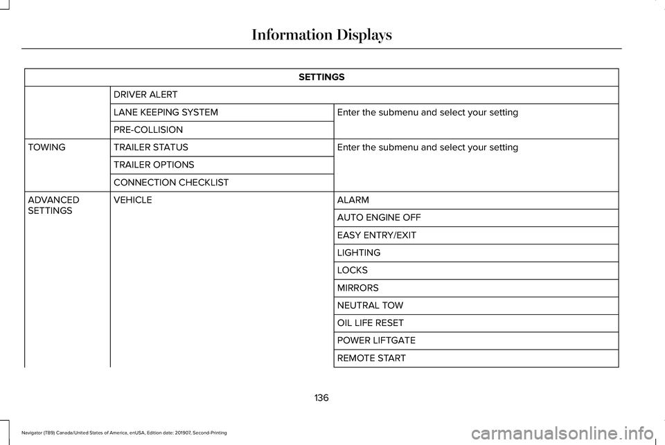
SETTINGS
DRIVER ALERT Enter the submenu and select your setting
LANE KEEPING SYSTEM
PRE-COLLISION
Enter the submenu and select your setting
TRAILER STATUS
TOWING
TRAILER OPTIONS
CONNECTION CHECKLIST ALARM
VEHICLE
ADVANCED
SETTINGS
AUTO ENGINE OFF
EASY ENTRY/EXIT
LIGHTING
LOCKS
MIRRORS
NEUTRAL TOW
OIL LIFE RESET
POWER LIFTGATE
REMOTE START
136
Navigator (TB9) Canada/United States of America, enUSA, Edition date: 201907, Second-Printing Information Displays
Page 219 of 622
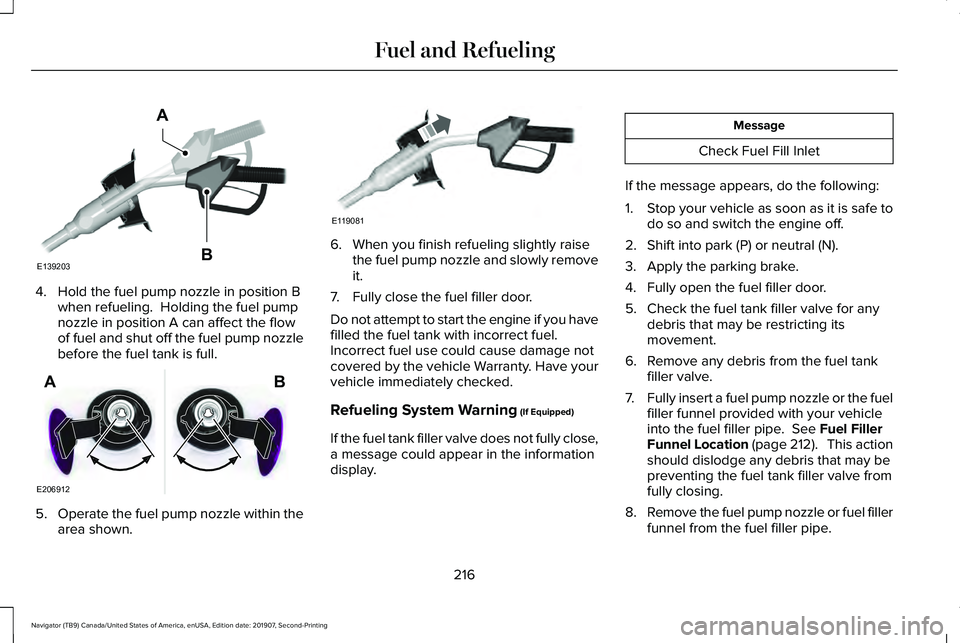
4. Hold the fuel pump nozzle in position B
when refueling. Holding the fuel pump
nozzle in position A can affect the flow
of fuel and shut off the fuel pump nozzle
before the fuel tank is full. 5.
Operate the fuel pump nozzle within the
area shown. 6. When you finish refueling slightly raise
the fuel pump nozzle and slowly remove
it.
7. Fully close the fuel filler door.
Do not attempt to start the engine if you have
filled the fuel tank with incorrect fuel.
Incorrect fuel use could cause damage not
covered by the vehicle Warranty. Have your
vehicle immediately checked.
Refueling System Warning (If Equipped)
If the fuel tank filler valve does not fully close,
a message could appear in the information
display. Message
Check Fuel Fill Inlet
If the message appears, do the following:
1. Stop your vehicle as soon as it is safe to
do so and switch the engine off.
2. Shift into park (P) or neutral (N).
3. Apply the parking brake.
4. Fully open the fuel filler door.
5. Check the fuel tank filler valve for any debris that may be restricting its
movement.
6. Remove any debris from the fuel tank filler valve.
7. Fully insert a fuel pump nozzle or the fuel
filler funnel provided with your vehicle
into the fuel filler pipe.
See Fuel Filler
Funnel Location (page 212). This action
should dislodge any debris that may be
preventing the fuel tank filler valve from
fully closing.
8. Remove the fuel pump nozzle or fuel filler
funnel from the fuel filler pipe.
216
Navigator (TB9) Canada/United States of America, enUSA, Edition date: 201907, Second-Printing Fuel and RefuelingE139203
A
B E206912
AB E119081
Page 220 of 622
9. Fully close the fuel filler door.
Note:
The message may not immediately
reset. If the message continues to appear
and a warning lamp illuminates, have your
vehicle checked as soon as possible.
FUEL CONSUMPTION
Advertised Capacity
The advertised capacity is the maximum
amount of fuel that you can add to the fuel
tank after running out of fuel. Included in the
advertised capacity is an empty reserve. The
empty reserve is an unspecified amount of
fuel that remains in the fuel tank when the
fuel gauge indicates empty.
Note: The amount of fuel in the empty
reserve varies and should not be relied upon
to increase driving range.
Fuel Economy
Your vehicle calculates fuel economy figures
through the trip computer average fuel
function. The first 1,000 mi (1,500 km) of driving is the
break-in period of the engine. A more
accurate measurement is obtained after
2,000 mi (3,000 km).
Impacting Fuel Economy
• Incorrect tire inflation pressures.
• Fully loading your vehicle.
• Carrying unnecessary weight.
• Adding certain accessories to your
vehicle such as bug deflectors, rollbars
or light bars, running boards and ski
racks.
• Using fuel blended with alcohol.
See
Fuel Quality (page 212).
• Fuel economy may decrease with lower
temperatures.
• Fuel economy may decrease when
driving short distances.
• You may get better fuel economy when
driving on flat terrain than when driving
on hilly terrain.
217
Navigator (TB9) Canada/United States of America, enUSA, Edition date: 201907, Second-Printing Fuel and Refueling
Page 221 of 622
EMISSION LAW
WARNING: Do not remove or alter
the original equipment floor covering or
insulation between it and the metal floor
of the vehicle. The floor covering and
insulation protect occupants of the vehicle
from the engine and exhaust system heat
and noise. On vehicles with no original
equipment floor covering insulation, do not
carry passengers in a manner that permits
prolonged skin contact with the metal floor.
Failure to follow these instructions may
result in fire or personal injury.
U.S. federal laws and certain state laws
prohibit removing or rendering inoperative
emission control system components. Similar
federal or provincial laws may apply in
Canada. We do not approve of any vehicle
modification without first determining
applicable laws. Tampering with emissions control
systems including related sensors
or the Diesel Exhaust Fluid system
can result in reduced engine power and the
illumination of the service engine soon light.
Tampering With a Noise Control
System
Federal laws prohibit the following acts:
• Removal or rendering inoperative by any
person other than for purposes of
maintenance.
• Repair or replacement of any device or
element of the design incorporated into
a new vehicle for the purpose of noise
control prior to its sale or delivery to the
ultimate purchaser or while it is in use.
• The use of the vehicle after any person
removes or renders inoperative any
device or element of the design. The U.S. Environmental Protection Agency
may presume to constitute tampering as
follows:
•
Removal of hood blanket, fender apron
absorbers, fender apron barriers,
underbody noise shields or acoustically
absorptive material.
• Tampering or rendering inoperative the
engine speed governor, to allow engine
speed to exceed manufacturer
specifications.
If the engine does not start, runs rough,
experiences a decrease in engine
performance, experiences excess fuel
consumption or produces excessive exhaust
smoke, check for the following:
• A plugged or disconnected air inlet
system hose.
• A plugged engine air filter element.
• Water in the fuel filter and water
separator.
• A clogged fuel filter.
• Contaminated fuel.
• Air in the fuel system, due to loose
connections.
218
Navigator (TB9) Canada/United States of America, enUSA, Edition date: 201907, Second-Printing Engine Emission Control
Page 240 of 622
GENERAL INFORMATION
Note:
Occasional brake noise is normal. If
a metal-to-metal, continuous grinding or
continuous squeal sound is present, the
brake linings may be worn-out and an
authorized dealer should check them. If the
vehicle has continuous vibration or shudder
in the steering wheel while braking, an
authorized dealer should check your vehicle.
Note: Brake dust may accumulate on the
wheels, even under normal driving
conditions. Some dust is inevitable as the
brakes wear and does not contribute to
brake noise. See Cleaning the Wheels
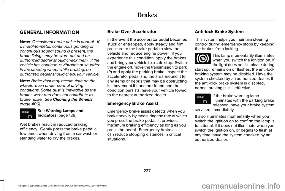
(page 400). See
Warning Lamps and
Indicators (page 128).
Wet brakes result in reduced braking
efficiency. Gently press the brake pedal a
few times when driving from a car wash or
standing water to dry the brakes. Brake Over Accelerator
In the event the accelerator pedal becomes
stuck or entrapped, apply steady and firm
pressure to the brake pedal to slow the
vehicle and reduce engine power. If you
experience this condition, apply the brakes
and bring your vehicle to a safe stop. Switch
the engine off, move the transmission to park
(P) and apply the parking brake. Inspect the
accelerator pedal and the area around it for
any items or debris that may be obstructing
its movement.If none are found and the
condition persists, have your vehicle towed
to the nearest authorized dealer.
Emergency Brake Assist
Emergency brake assist detects when you
brake heavily by measuring the rate at which
you press the brake pedal. It provides
maximum braking efficiency as long as you
press the pedal. Emergency brake assist
can reduce stopping distances in critical
situations.Anti-lock Brake System
This system helps you maintain steering
control during emergency stops by keeping
the brakes from locking. This lamp momentarily illuminates
when you switch the ignition on. If
the light does not illuminate during
start up, remains on or flashes, the anti-lock
braking system may be disabled. Have the
system checked by an authorized dealer. If
the anti-lock brake system is disabled,
normal braking is still effective. If the brake warning lamp
illuminates with the parking brake
released, have your brake system
serviced immediately.
It also illuminates momentarily when you
switch the ignition on to confirm the lamp is
functional. If it does not illuminate when you
switch the ignition on, or begins to flash at
any time, have the system checked by an
authorized dealer.
237
Navigator (TB9) Canada/United States of America, enUSA, Edition date: 201907, Second-Printing BrakesE138644 E138644
Page 326 of 622
TRAILER SWAY CONTROL (IF EQUIPPED)
WARNING: Turning off trailer sway
control increases the risk of loss of vehicle
control, serious injury or death. Ford does
not recommend disabling this feature
except in situations where speed reduction
may be detrimental (such as hill climbing),
the driver has significant trailer towing
experience, and can control trailer sway
and maintain safe operation.
Note: This feature does not prevent trailer
sway, but reduces it once it begins.
Note: This feature cannot stop all trailers
from swaying.
Note: In some cases, if vehicle speed is too
high, the system may activate multiple times,
gradually reducing vehicle speed. This feature applies your vehicle brakes at
individual wheels and, if necessary, reduces
engine power. If the trailer begins to sway,
the stability control light flashes and the
message TRAILER SWAY REDUCE SPEED
appears in the information display. The first
thing to do is slow your vehicle down, then
pull safely to the side of the road and check
for proper tongue load and trailer load
distribution.
See Load Carrying (page 301).
RECOMMENDED TOWING
WEIGHTS
Note: Do not exceed the trailer weight
for your vehicle configuration listed in
the chart below.
Note: Make sure to take into
consideration trailer frontal area. Do not
exceed 55 ft² (5.11 m²) if your vehicle has
the standard towing package, or 60 ft²
(5.57 m²) if your vehicle has the heavy
duty package. Note:
Exceeding this limitation may
significantly reduce the performance of
your towing vehicle. Selecting a trailer
with a low aerodynamic drag and
rounded front design helps optimize
performance and fuel economy.
Note: For high altitude operation,
reduce the gross combined weight by
2% per 1,000 ft (300 m) starting at the
1,000 ft (300 m) elevation point.
Note: Certain states require electric
trailer brakes for trailers over a specified
weight. Be sure to check state
regulations for this specified weight. The
maximum trailer weights listed may be
limited to this specified weight, as the
vehicle ’s electrical system may not
include the wiring connector needed to
activate electric trailer brakes.
Your vehicle may tow a trailer provided
the maximum trailer weight is less than
or equal to the maximum trailer weight
listed for your vehicle configuration on
the following chart.
323
Navigator (TB9) Canada/United States of America, enUSA, Edition date: 201907, Second-Printing Towing
Page 331 of 622
Note:
These are hitch ratings only. Actual
vehicle ratings are dependent on engine,
transmission and axle combinations.
Weight-distributing Hitch WARNING: Do not adjust the spring
bars so that your vehicle's rear bumper is
higher than before attaching the trailer.
Doing so will defeat the function of the
weight-distributing hitch, which may cause
unpredictable handling, and could result
in serious personal injury.
When hooking-up a trailer using a
weight-distributing hitch, always use the
following procedure:
1. Park the loaded vehicle, without the trailer, on a level surface.
2. Measure the height to the top of your vehicle's front wheel opening on the
fender. This is H1.
3. Attach the loaded trailer to your vehicle without the weight-distributing bars
connected. 4. Measure the height to the top of your
vehicle's front wheel opening on the
fender a second time. This is H2.
5. Install and adjust the tension in the weight-distributing bars so that the height
of your vehicle's front wheel opening on
the fender is approximately half the way
down from H2, toward H1.
6. Check that the trailer is level or slightly nose down toward your vehicle. If not,
adjust the ball height accordingly and
repeat Steps 2-6.
When the trailer is level or slightly nose down
toward the vehicle:
• Lock the bar tension adjuster in place.
• Check that the trailer tongue securely
attaches and locks onto the hitch.
• Install safety chains, lighting and trailer
brake controls as required by law or the
trailer manufacturer. Safety Chains
Note:
Do not attach safety chains to the
bumper. Always connect the safety chains
to the frame or hook retainers of your trailer
hitch.
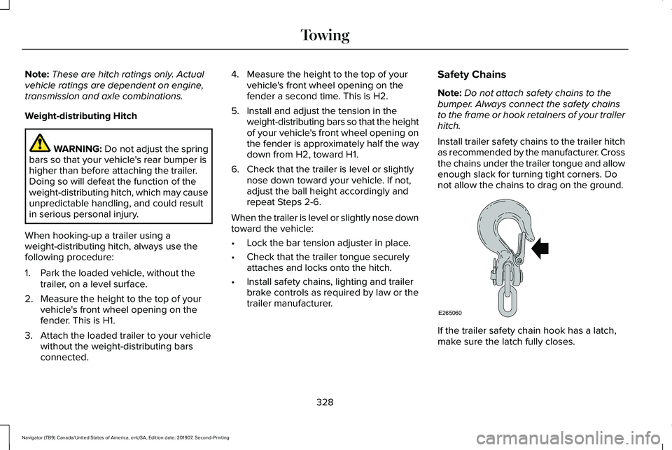
Install trailer safety chains to the trailer hitch
as recommended by the manufacturer. Cross
the chains under the trailer tongue and allow
enough slack for turning tight corners. Do
not allow the chains to drag on the ground. If the trailer safety chain hook has a latch,
make sure the latch fully closes.
328
Navigator (TB9) Canada/United States of America, enUSA, Edition date: 201907, Second-Printing TowingE265060
Page 339 of 622

WARNING: Shifting the transfer case
to its neutral position for recreational
towing may cause the vehicle to roll, even
if the transmission is in park (P). It may
injure the driver and others. Make sure you
press the foot brake and the vehicle is in
a secure, safe position when you shift to
neutral (N).
Note: Failing to put the transfer case in its
neutral position can damage vehicle
components.
Note: You can check four-wheel-down
towing status at any time by opening the
driver's door or turning the ignition to the
accessory or on position. A message
appears in the information display confirming
your vehicle is in neutral tow.
To exit four-wheel-down towing and return
the transfer case to its
2H position:
1. With your vehicle still properly secured to the tow vehicle, press the brake pedal
and start the engine.
2. Switch your vehicle off by pressing the engine
START/STOP button once. 3.
Place your vehicle in accessory mode by
pressing the start button once without
pressing the brake pedal.
4. Press the brake pedal.
5. Place the transmission back into park (P).
6. Release the brake pedal.
Note: If completed successfully, the
information display shows
2H and Neutral
Tow Disabled.
Note: If the indicator light and message do
not display, you must perform the procedure
again from the beginning.
Note: You may hear an audible noise as the
transfer case shifts out of its neutral position,
this is normal.
Note: If Shift Delayed Pull Forward displays
in the instrument cluster, transfer case gear
tooth blockage is present. See the
instructions following this section.
7. Apply the parking brake, then disconnect
your vehicle from the tow vehicle. 8. Release the parking brake, start the
engine, and shift the transmission into
drive (D) to make sure the transfer case
is out of the neutral tow position.
9. If the transfer case does not successfully
shift out of neutral (N), set the parking
brake until you can have your vehicle
serviced.
Resolving the Shift Delayed Pull Forward
or To Exit 4x4 LOW Shift to N Message
If the instrument cluster displays these
messages, perform the following:
1. Press and hold the brake pedal.
2. Put the transmission into neutral (N), then
start the engine.
3. With the engine running, shift the transmission into drive (D) and let the
vehicle roll forward, up to
3 ft (1 m). You
may hear an audible noise as the transfer
case shifts out of its neutral position. This
is normal.
4. Make sure the instrument cluster displays
Neutral Tow Disabled
.
336
Navigator (TB9) Canada/United States of America, enUSA, Edition date: 201907, Second-Printing Towing
Page 341 of 622
•
Do not rest your foot on the brake pedal
while driving.
• Avoid carrying unnecessary weight.
• Avoid adding particular accessories to
your vehicle (e.g. bug deflectors,
rollbars/light bars, running boards, ski
racks).
• Avoid driving with the wheels out of
alignment.
BREAKING-IN
You need to break in new tires for
approximately 300 mi (480 km). During this
time, your vehicle may exhibit some unusual
driving characteristics.
Avoid driving too fast during the first 1,000 mi
(1,600 km)
. Vary your speed frequently and
change up through the gears early. Do not
labor the engine.
Do not tow during the first
1,000 mi
(1,600 km). DRIVING THROUGH WATER WARNING:
Do not drive through
flowing or deep water as you may lose
control of your vehicle.
Note: Driving through standing water can
cause vehicle damage.
Note: Engine damage can occur if water
enters the air filter.
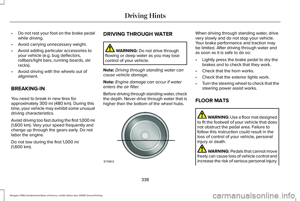
Before driving through standing water, check
the depth. Never drive through water that is
higher than the bottom of the wheel hubs. When driving through standing water, drive
very slowly and do not stop your vehicle.
Your brake performance and traction may
be limited. After driving through water and
as soon as it is safe to do so:
•
Lightly press the brake pedal to dry the
brakes and to check that they work.
• Check that the horn works.
• Check that the exterior lights work.
• Turn the steering wheel to check that the
steering power assist works.
FLOOR MATS WARNING:
Use a floor mat designed
to fit the footwell of your vehicle that does
not obstruct the pedal area. Failure to
follow this instruction could result in the
loss of control of your vehicle, personal
injury or death. WARNING:
Pedals that cannot move
freely can cause loss of vehicle control and
increase the risk of serious personal injury.
338
Navigator (TB9) Canada/United States of America, enUSA, Edition date: 201907, Second-Printing Driving HintsE176913
Page 383 of 622
ENGINE COOLANT CHECK
WARNING: Do not remove the
coolant reservoir cap when the engine is
on or the cooling system is hot. Wait 10
minutes for the cooling system to cool
down. Cover the coolant reservoir cap with
a thick cloth to prevent the possibility of
scalding and slowly remove the cap.
Failure to follow this instruction could result
in personal injury. WARNING: Do not put coolant in the
windshield washer reservoir. If sprayed on
the windshield, coolant could make it
difficult to see through the windshield. WARNING:
To reduce the risk of
personal injury, make sure the engine is
cool before unscrewing the coolant
pressure relief cap. The cooling system is
under pressure. Steam and hot liquid can
come out forcefully when you loosen the
cap slightly. WARNING:
Do not add coolant
further than the MAX mark.
When the engine is cold, check the
concentration and level of the coolant at the
intervals listed in the scheduled maintenance
information.
See Scheduled Maintenance
(page 537).
Note: Make sure that the coolant level is
between the
MIN and MAX marks on the
coolant reservoir.
Note: Coolant expands when it is hot. The
level may extend beyond the
MAX mark.
Maintain coolant concentration within 48%
to 50%, which equates to a freeze point
between
-29°F (-34°C) and -35°F (-37°C).
Coolant concentration should be checked
using a refractometer. We do not recommend
the use of hydrometers or coolant test strips
for measuring coolant concentration. Adding Coolant WARNING:
Do not remove the
coolant reservoir cap when the engine is
on or the cooling system is hot. Wait 10
minutes for the cooling system to cool
down. Cover the coolant reservoir cap with
a thick cloth to prevent the possibility of
scalding and slowly remove the cap.
Failure to follow this instruction could result
in personal injury. WARNING:
Do not add engine
coolant when the engine is on or the
cooling system is hot. Failure to follow this
instruction could result in personal injury.
Note: Automotive fluids are not
interchangeable. Take care not to put
engine coolant in the windshield washer fluid
reservoir or windshield washer fluid in the
engine coolant reservoir.
380
Navigator (TB9) Canada/United States of America, enUSA, Edition date: 201907, Second-Printing Maintenance