clock LINCOLN TOWN CAR 1998 Owners Manual
[x] Cancel search | Manufacturer: LINCOLN, Model Year: 1998, Model line: TOWN CAR, Model: LINCOLN TOWN CAR 1998Pages: 188, PDF Size: 1.29 MB
Page 4 of 188
TAPESEEK
TUNE
REW
FFSIDE 1 2
COMP
SHUFF
EJ
RDS
SCAN AUTO
123
4
56
BASS
TREBSELBAL
FADE
MAX
A/CAUTO
FRONT
REAR
SELECTRESET
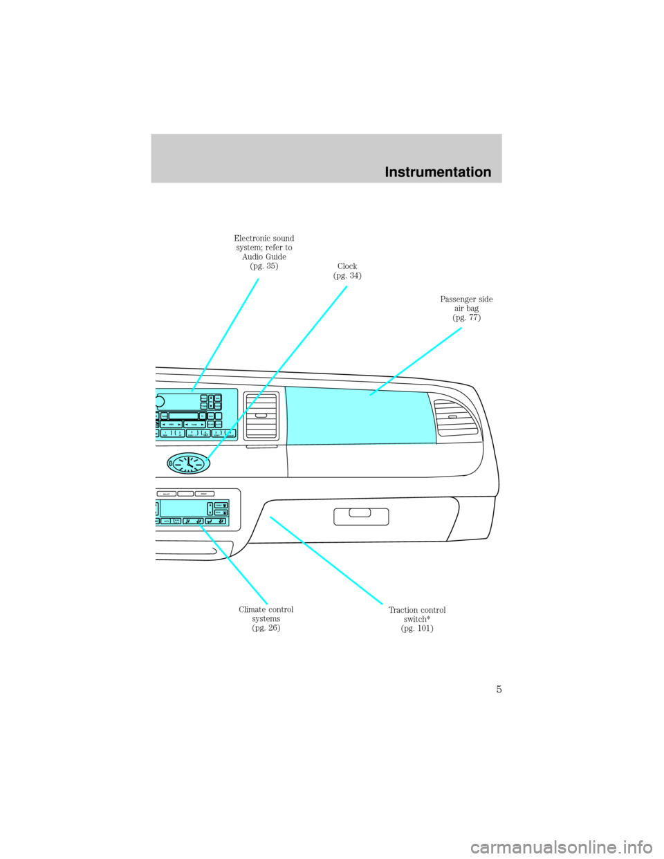
Climate control
systems
(pg. 26)Clock
(pg. 34) Electronic sound
system; refer to
Audio Guide
(pg. 35)
Passenger side
air bag
(pg. 77)
Traction control
switch*
(pg. 101)
Instrumentation
5
Page 23 of 188
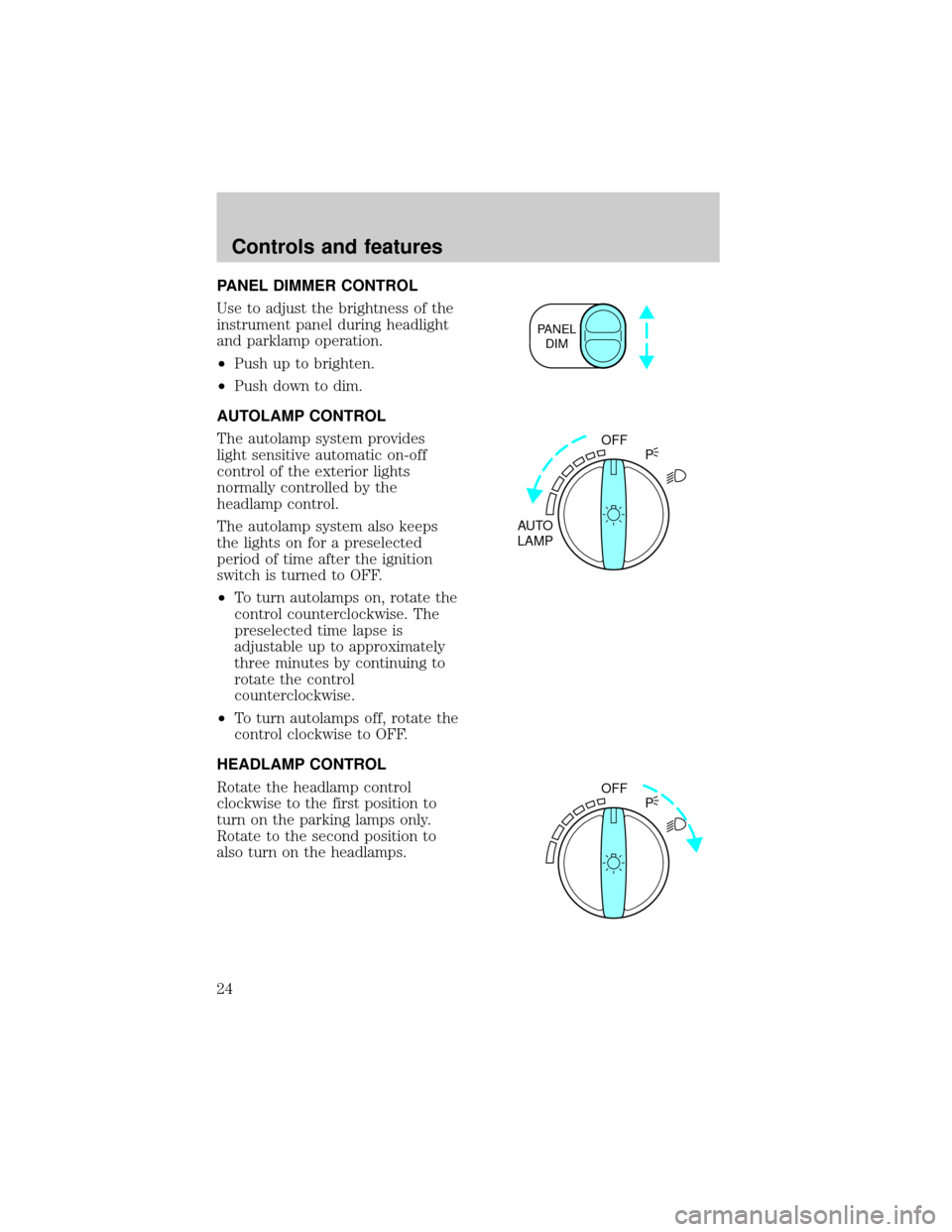
PANEL DIMMER CONTROL
Use to adjust the brightness of the
instrument panel during headlight
and parklamp operation.
²Push up to brighten.
²Push down to dim.
AUTOLAMP CONTROL
The autolamp system provides
light sensitive automatic on-off
control of the exterior lights
normally controlled by the
headlamp control.
The autolamp system also keeps
the lights on for a preselected
period of time after the ignition
switch is turned to OFF.
²To turn autolamps on, rotate the
control counterclockwise. The
preselected time lapse is
adjustable up to approximately
three minutes by continuing to
rotate the control
counterclockwise.
²To turn autolamps off, rotate the
control clockwise to OFF.
HEADLAMP CONTROL
Rotate the headlamp control
clockwise to the first position to
turn on the parking lamps only.
Rotate to the second position to
also turn on the headlamps.
PANEL
DIM
OFF
AUTO
LAMPP
OFF
P
Controls and features
24
Page 33 of 188
reduce your ability to see
through your windshield. Also,
avoid placing small objects on
top of your instrument panel.
These objects can fall down into
the defroster outlets and block
airflow and possibly damage
your climate control system.
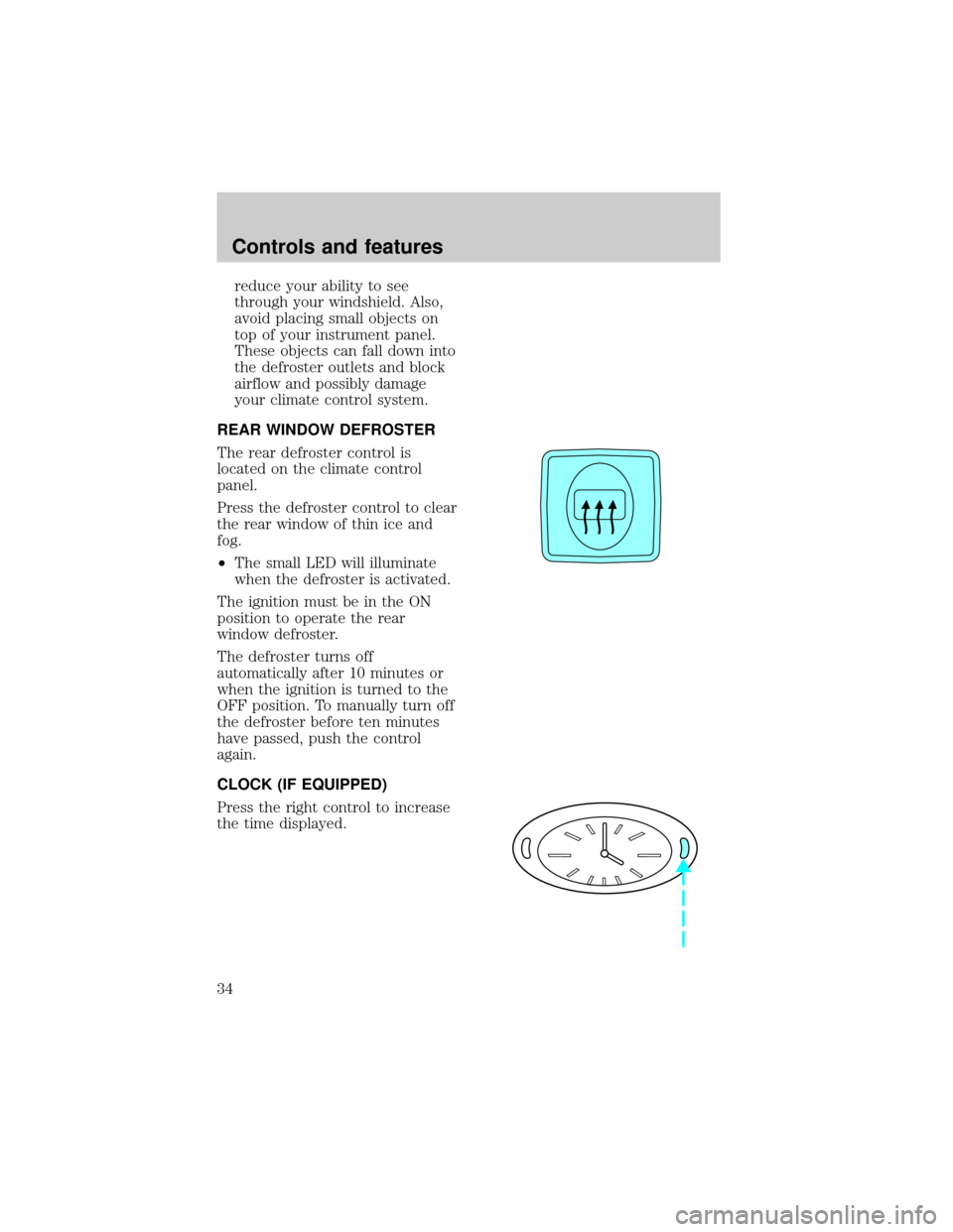
REAR WINDOW DEFROSTER
The rear defroster control is
located on the climate control
panel.
Press the defroster control to clear
the rear window of thin ice and
fog.
²The small LED will illuminate
when the defroster is activated.
The ignition must be in the ON
position to operate the rear
window defroster.
The defroster turns off
automatically after 10 minutes or
when the ignition is turned to the
OFF position. To manually turn off
the defroster before ten minutes
have passed, push the control
again.
CLOCK (IF EQUIPPED)
Press the right control to increase
the time displayed.
Controls and features
34
Page 118 of 188

Fuse/Relay
LocationFuse Amp
RatingDescription
19 10A EATC, Clock, Instrument Cluster, PCM
20 7.5A Lighting Control Module (LCM), ABS,
Shift Lock
21 20A Multi-Function Switch
22 20A Multi-Function Switch, High Mounted
Stop Lamps
23 20A Datalink Connector, I/P Cigar Lighter
24 5A Front Radio Control Unit
25 15A Lighting Control Module (LCM)
26 5A Digital Transmission Range (DTR)
Sensor
27 20A Fuel Filler Door Release Switch
28 10A Heated Mirrors
29 20A LF Door Module
30 7.5A LF Seat Module, Trunk Lid Release
Switch, Door Lock Switches, LF Seat
Control Switch, LF Door Module, Power
Mirror Switch
31 7.5A Main Light Switch, Lighting Control
Module (LCM)
32 15A Not Used
33 15A Front Radio Control Unit, Digital
Compact Disk Changer, Cellular
Telephone Transceiver
Relay 1 - Accessory Delay Relay
Roadside emergencies
119
Page 123 of 188
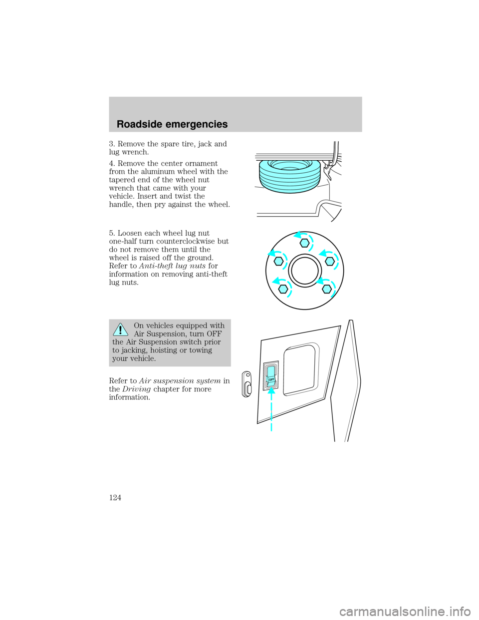
3. Remove the spare tire, jack and
lug wrench.
4. Remove the center ornament
from the aluminum wheel with the
tapered end of the wheel nut
wrench that came with your
vehicle. Insert and twist the
handle, then pry against the wheel.
5. Loosen each wheel lug nut
one-half turn counterclockwise but
do not remove them until the
wheel is raised off the ground.
Refer toAnti-theft lug nutsfor
information on removing anti-theft
lug nuts.
On vehicles equipped with
Air Suspension, turn OFF
the Air Suspension switch prior
to jacking, hoisting or towing
your vehicle.
Refer toAir suspension systemin
theDrivingchapter for more
information.
OFF
Roadside emergencies
124
Page 124 of 188
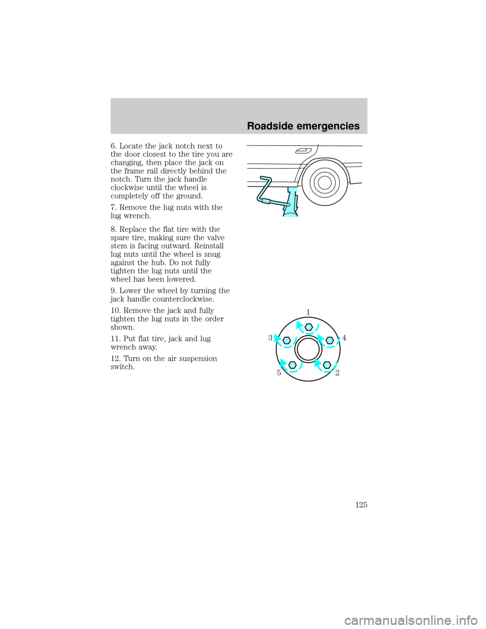
6. Locate the jack notch next to
the door closest to the tire you are
changing, then place the jack on
the frame rail directly behind the
notch. Turn the jack handle
clockwise until the wheel is
completely off the ground.
7. Remove the lug nuts with the
lug wrench.
8. Replace the flat tire with the
spare tire, making sure the valve
stem is facing outward. Reinstall
lug nuts until the wheel is snug
against the hub. Do not fully
tighten the lug nuts until the
wheel has been lowered.
9. Lower the wheel by turning the
jack handle counterclockwise.
10. Remove the jack and fully
tighten the lug nuts in the order
shown.
11. Put flat tire, jack and lug
wrench away.
12. Turn on the air suspension
switch.
1
4 3
52
Roadside emergencies
125
Page 140 of 188
recovery reservoir-DO NOT ADD
DIRECTLY TO THE RADIATOR.
Add straight water only in an
emergency, but you should replace
it with a 50/50 mixture of coolant
and distilled water as soon as
possible.
Check the coolant level in the
coolant recovery reservoir the next
few times you drive the vehicle. If
necessary, add enough of a 50/50
mixture of coolant and water to
bring the liquid level to the fill line
on the reservoir.
Never remove the coolant
recovery cap while the
engine is running or hot.
If you must remove the coolant
recovery cap, follow these steps to
avoid personal injury:
1. Before you remove the cap, turn
the engine off and let it cool.
2. When the engine is cool, wrap a
thick cloth around the cap. Slowly
turn cap counterclockwise until
pressure begins to release.
3. Step back while the pressure
releases.
4. When you are sure that all the
pressure has been released, use
the cloth to turn it
counterclockwise and remove the
cap.
Use Ford Premium Cooling System
Fluid E2FZ-19549±AA (in Canada,
Motorcraft CXC-8±B) or an
equivalent premium engine coolant
Maintenance and care
141
Page 149 of 188

quantity of grease to the top of
each battery terminal to help
prevent corrosion.
If your battery has a
cover/shield, make sure it is
reinstalled after the battery is
replaced.
Because your vehicle's engine is
electronically controlled by a
computer, some control conditions
are maintained by power from the
battery. When the battery is
disconnected or a new battery is
installed, the engine must relearn
its idle conditions before your
vehicle will drive properly. To
begin this process:
1. Put the gearshift in P (Park),
turn off all accessories and start
the vehicle.
2. Let the engine idle for at least
one minute.
3. The relearning process will
automatically complete as you
drive the vehicle.
²If you do not allow the engine to
relearn its idle, the idle quality
of your vehicle may be adversely
affected until the idle is
eventually relearned.
²If the battery has been
disconnected or a new battery
has been installed, the clock and
the preset radio stations must
be reset once the battery is
reconnected.
Maintenance and care
150
Page 167 of 188
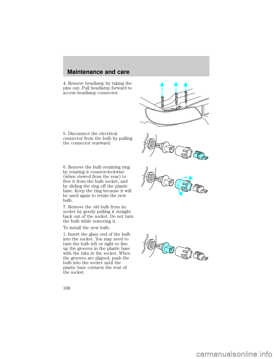
4. Remove headlamp by taking the
pins out. Pull headlamp forward to
access headlamp connector.
5. Disconnect the electrical
connector from the bulb by pulling
the connector rearward.
6. Remove the bulb retaining ring
by rotating it counterclockwise
(when viewed from the rear) to
free it from the bulb socket, and
by sliding the ring off the plastic
base. Keep the ring because it will
be used again to retain the new
bulb.
7. Remove the old bulb from its
socket by gently pulling it straight
back out of the socket. Do not turn
the bulb while removing it.
To install the new bulb:
1. Insert the glass end of the bulb
into the socket. You may need to
turn the bulb left or right to line
up the grooves in the plastic base
with the tabs in the socket. When
the grooves are aligned, push the
bulb into the socket until the
plastic base contacts the rear of
the socket.
Maintenance and care
168
Page 168 of 188

2. Slip the bulb retaining ring over
the plastic base until it contacts
the rear of the socket by rotating it
clockwise until you feel a ªstop.º
3. Push the electrical connector
into the rear of the plastic base
until it snaps, locking it into
position.
4. Turn the headlamps on and
make sure they work properly. If
the headlamp was correctly aligned
before you changed the bulb, you
should not need to align it again.
5. Carefully insert the headlamp
assembly into the vehicle making
sure the alignment pins are
inserted into the proper holes and
into the guides.
AIMING THE HEADLAMPS
Your vehicle is equipped with a
Vehicle Headlamp Aim Device
(VHAD) on each headlamp body.
Each headlamp may be properly
aimed in the horizontal direction
(left/right) and the vertical
position (up/down).
A non-zero bubble reading does
not necessarily indicate out-of-aim
headlamps. If your vehicle is not
positioned on a level surface, the
slope will be included in the level
indicator. Therefore, vertical
headlamp adjustment should be
performed only when beam
direction appears to be incorrect
or a level surface can not be
verified.
Maintenance and care
169