belt MASERATI GHIBLI 2019 Owner's Guide
[x] Cancel search | Manufacturer: MASERATI, Model Year: 2019, Model line: GHIBLI, Model: MASERATI GHIBLI 2019Pages: 384, PDF Size: 13.33 MB
Page 101 of 384
Power Lumbar
Push the switch 3 forward or rearward
to increase or decrease the lumbar
support.
Push the switch 3 upward or
downward to raise or lower the
lumbar support.
WARNING!
• Never adjust the seat while driving.
You could lose control of the vehicle.
Moving the seat could distract you
or make you press a pedal
unintentionally.
• Seats should be adjusted before
fastening the seat belts and while
the vehicle is parked.
• Do not ride with the seatback
reclined so that the shoulder belt is
no longer resting against your chest.
In a collision you could slide under
the seat belt, which could result in
serious injury or death.
CAUTION!
Do not place any object under a
power seat or obstruct its movement
as it may cause damage to the seat
controls. Seat movement may become limited if there is an obstruction in the
way.
Front Heated Seats The front seats are equipped with
heaters in both seat cushions and
seatbacks.
The seats comfort commands are in
the “Climate” screen of the MTC+.
They are present in the "Climate"
screen even when the A/C is off. See
“Air Conditioning Controls” in section
“Dashboard Instruments and
Controls” for further details.
WARNING!
• Persons with low skin sensitivity
because of advanced age, chronic
illness, diabetes, spinal cord injury,
medication, alcohol use, exhaustion
or other physical conditions must be
careful when using the seat heater.
It may cause irritation even at low
temperatures, especially if used for
long periods of time.
• Do not place anything on the seat
that insulates against heat, such as a
blanket or cushion. This may cause
the seat heater to overheat. Front Seats Heat Function
NOTE:
The
engine must
be running for the
heated seats to operate.
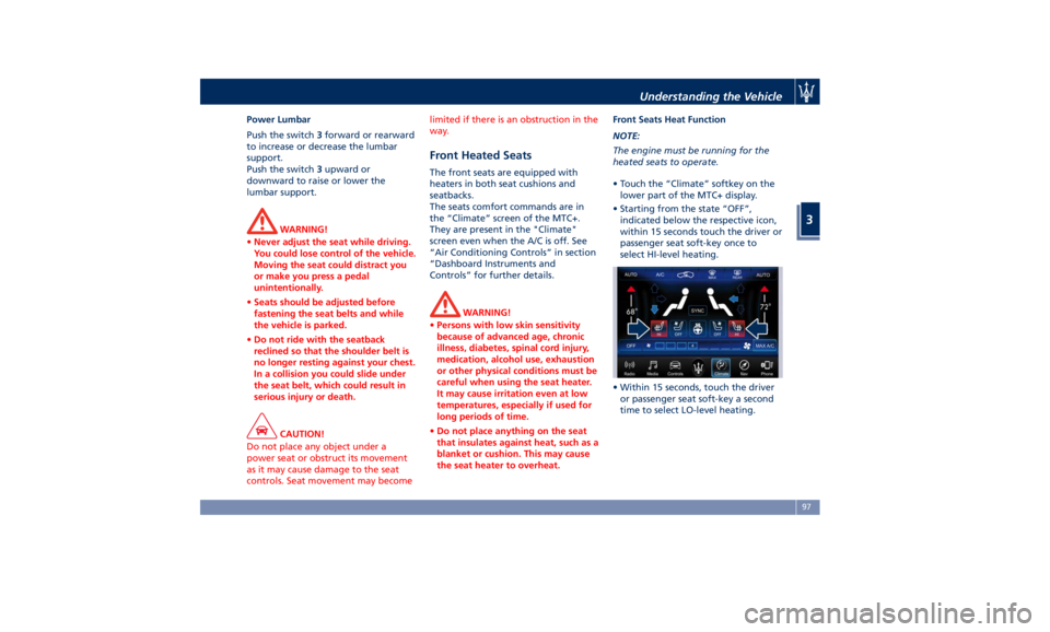
• Touch the “Climate” softkey on the
lower part of the MTC+ display.
• Starting from the state “OFF”,
indicated below the respective icon,
within 15 seconds touch the driver or
passenger seat soft-key once to
select HI-level heating.
• Within 15 seconds, touch the driver
or passenger seat soft-key a second
time to select LO-level heating.Understanding the Vehicle
3
97
Page 105 of 384
to the driver by moving the seat for
Easy Exit or Easy Entry.
Each stored memory setting will have
an associated easy entry/exit position.
NOTE:
The Easy Entry/Exit feature can be
enabled or disabled using the MTC+
System, refer to “MTC+ Settings” in
section “Dashboard Instruments and
Controls” for further information.
Rear Seats Rear seats can fit three passengers.
Seats, head restraints and seat belts
are parts of the occupant restraint
system of the vehicle.
For further information, see chapter
“Occupants Restraint Systems” in
section “Before Starting” and “Head
Restraints” in this section.
WARNING!
Be sure everyone in your vehicle is in
a seat and using a seat belt properly.
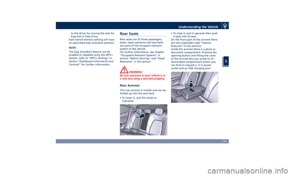
Rear Armrest The rear armrest is mobile and can be
folded up into the seat back.
• To lower it, pull the stripe as
indicated. • To close it, pull it upwards then push
it back into its seat.
On the front part of the armrest there
are two cupholders (see “Interior
Features” in this section).
Inside the armrest there is a glove or
document compartment. Pressing the
opening button and lifting the cover
of the armrest box you access to an
illuminated compartment where you
can find on request a 12 V power
outlet and an USB charging port.Understanding the Vehicle
3
101
Page 137 of 384
please contact Client Service at
1-800-977.2107 or write to:
[email protected].
CAUTION!
When selling the vehicle, you should
contact the above mentioned Client
Service to have your device removed
from the list of activated devices
registered in your name. Do not
simply give your control unit password
to a new owner. To avoid improper
internet access in your name and
allow new owner registration you
must de-register with the service
provider. A new owner will not be
able to register the device if it still
appears registered in the prior
owner's name. If you are a subsequent
owner, the unit could be improperly
monitored (usage and location), if it is
still registered to a prior owner. Cargo Area WARNING!
To help protect against personal
injury, passengers must not be seated
in the rear cargo area. The rear cargo
space is intended for load carrying
purposes only, not for passengers,
who should sit in seats and use seat
belts.
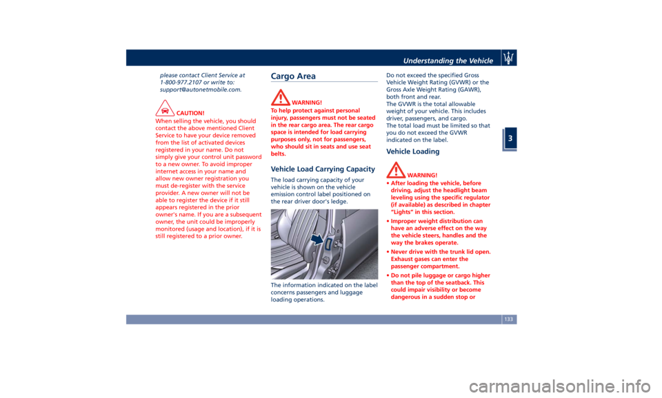
Vehicle Load Carrying Capacity The load carrying capacity of your
vehicle is shown on the vehicle
emission control label positioned on
the rear driver door's ledge.
The information indicated on the label
concerns passengers and luggage
loading operations. Do not exceed the specified Gross
Vehicle Weight Rating (GVWR) or the
Gross Axle Weight Rating (GAWR),
both front and rear.
The GVWR is the total allowable
weight of your vehicle. This includes
driver, passengers, and cargo.
The total load must be limited so that
you do not exceed the GVWR
indicated on the label.
Vehicle Loading WARNING!
• After loading the vehicle, before
driving, adjust the headlight beam
leveling using the specific regulator
(if available) as described in chapter
“Lights” in this section.
• Improper weight distribution can
have an adverse effect on the way
the vehicle steers, handles and the
way the brakes operate.
• Never drive with the trunk lid open.
Exhaust gases can enter the
passenger compartment.
• Do not pile luggage or cargo higher
than the top of the seatback. This
could impair visibility or become
dangerous in a sudden stop orUnderstanding the Vehicle
3
133
Page 139 of 384
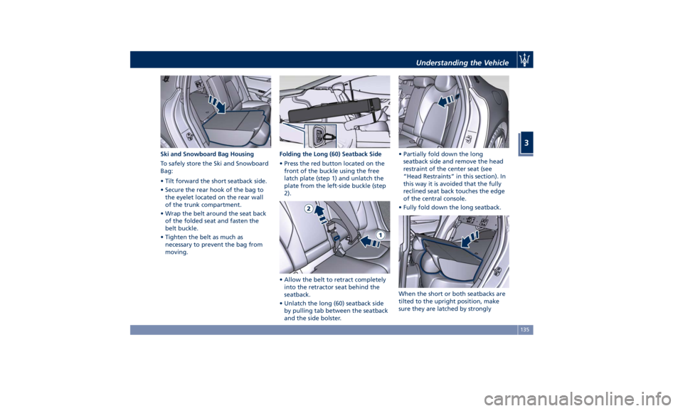
Ski and Snowboard Bag Housing
To safely store the Ski and Snowboard
Bag:
• Tilt forward the short seatback side.
• Secure the rear hook of the bag to
the eyelet located on the rear wall
of the trunk compartment.
• Wrap the belt around the seat back
of the folded seat and fasten the
belt buckle.
• Tighten the belt as much as
necessary to prevent the bag from
moving. Folding the Long (60) Seatback Side
• Press the red button located on the
front of the buckle using the free
latch plate (step 1) and unlatch the
plate from the left-side buckle (step
2).
• Allow the belt to retract completely
into the retractor seat behind the
seatback.
• Unlatch the long (60) seatback side
by pulling tab between the seatback
and the side bolster. • Partially fold down the long
seatback side and remove the head
restraint of the center seat (see
“Head Restraints” in this section). In
this way it is avoided that the fully
reclined seat back touches the edge
of the central console.
• Fully fold down the long seatback.
When the short or both seatbacks are
tilted to the upright position, make
sure they are latched by stronglyUnderstanding the Vehicle
3
135
Page 140 of 384
pulling on the top of the seatback
above the seat strap.
NOTE:
When the seatback is tilted to the
upright position, reassemble the head
restraint of the center seat (see “Head
Restraints” in this section) make sure
the seatbelt of the rear central
position is in the proper condition for
use.
WARNING!
• Make sure that the seatback is
securely locked into position. If the
seatback is not securely locked into
position, the seat will not provide
the proper stability for child seats
and/or passengers. An improperly
latched seat could cause serious
injury.
• The cargo area in the rear of the
vehicle with the rear seatbacks in
the folded down position should not
be used as a play area by children
when the vehicle is in motion. They
could be seriously injured in a
collision. Children should be seated
and use proper restraint system. Power Sunroof with
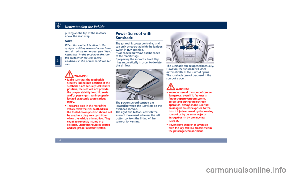
Sunshade The sunroof is power controlled and
can only be operated with the ignition
switch in RUN position.
It can slide lengthways and be raised
at the rear (tilting).
By opening the sunroof a front flap
rises automatically in order to deviate
the air flow.
The power sunroof controls are
located between the sun visors on the
overhead console.
The right two buttons controls the
sunroof movement, whereas the left
button controls the lifting of the
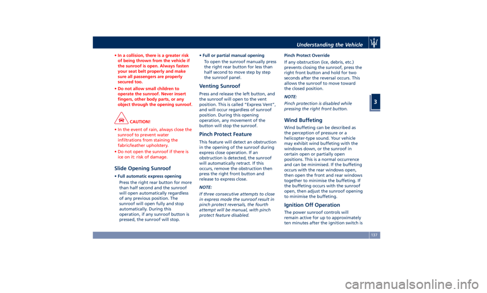
sunroof for venting. The sunshade can be opened manually.
However, the sunshade will open
automatically as the sunroof opens.
The sunshade cannot be closed if the
sunroof is open.
WARNING!
• Improper use of the sunroof can be
dangerous, even if it features a
finger-trap prevention system.
Before and during the sunroof
operation, always make sure that
passengers are not exposed to the
risk of injuries caused by the moving
sunroof or by personal objects
dragged or hit by the moving
sunroof.
• Never leave children in a vehicle
with the key fob RKE transmitter in
the passenger compartment.Understanding the Vehicle
3
136
Page 141 of 384
• In a collision, there is a greater risk
of being thrown from the vehicle if
the sunroof is open. Always fasten
your seat belt properly and make
sure all passengers are properly
secured too.
• Do not allow small children to
operate the sunroof. Never insert
fingers, other body parts, or any
object through the opening sunroof.
CAUTION!
• In the event of rain, always close the
sunroof to prevent water
infiltrations from staining the
fabric/leather upholstery.
• Do not open the sunroof if there is
ice on it: risk of damage.
Slide Opening Sunroof • Full automatic express opening
Press the right rear button for more
than half second and the sunroof
will open automatically regardless
of any previous position. The
sunroof will open fully and stop
automatically. During this
operation, if any sunroof button is
pressed, the sunroof will stop. • Full or partial manual opening
To open the sunroof manually press
the right rear button for less than
half second to move step by step
the sunroof panel.
Venting Sunroof Press and release the left button, and
the sunroof will open to the vent
position. This is called “Express Vent”,
and will occur regardless of sunroof
position. During this opening
operation, any movement of the
button will stop the sunroof.
Pinch Protect Feature This feature will detect an obstruction
in the opening of the sunroof during
express close operation. If an
obstruction is detected, the sunroof
will automatically retract. If this
occurs, remove the obstruction then
press the right front button and
release to express close.
NOTE:
If three consecutive attempts to close
in express mode the sunroof result in
pinch protect reversals, the fourth
attempt will be manual, with pinch
protect feature disabled. Pinch Protect Override
If any obstruction (ice, debris, etc.)
prevents closing the sunroof, press the
right front button and hold for two
seconds after the reversal occurs. This
allows the sunroof to move toward
the closed position.
NOTE:
Pinch protection is disabled while
pressing the right front button.
Wind Buffeting Wind buffeting can be described as
the perception of pressure or a
helicopter-type sound. Your vehicle
may exhibit wind buffeting with the
windows down, or the sunroof in
certain open or partially open
positions. This is a normal occurrence
and can be minimised. If the buffeting
occurs with the rear windows open,
then open the front and rear windows
together to minimise the buffeting. If
the buffeting occurs with the sunroof
open, then adjust the sunroof opening
to minimise the buffeting.
Ignition Off Operation The power sunroof controls will
remain active for up to approximately
ten minutes after the ignition switch isUnderstanding the Vehicle
3
137
Page 154 of 384
(Continued)
checked as soon as possible at an
Authorized Maserati Dealer.
Air Bag Indicator Light
This
light will illuminate for a
few seconds for a bulb check
when the ignition switch is in
RUN . If the light does not
illuminate while starting the engine,
stays lit, or switches on while driving,
have the system checked at an
Authorized Maserati Dealer as soon as
possible.
In the latter case, the message will
remain displayed: to hide it, press the
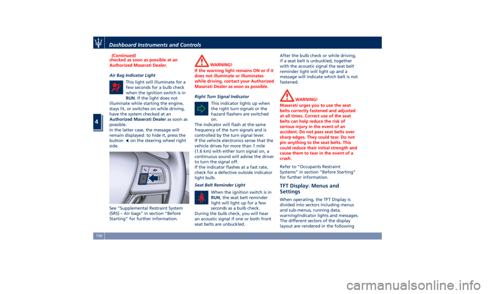
button
on the steering wheel right
side.
See “Supplemental Restraint System
(SRS) – Air bags” in section “Before
Starting” for further information. WARNING!
If the warning light remains ON or if it
does not illuminate or illuminates
while driving, contact your Authorized
Maserati Dealer as soon as possible.
Right Turn Signal Indicator
This
indicator lights
up when
the right turn signals or the
hazard flashers are switched
on.
The indicator will flash at the same
frequency of the turn signals and is
controlled by the turn signal lever.
If the vehicle electronics sense that the
vehicle drives for more than 1 mile
(1.6 km) with either turn signal on, a
continuous sound will advise the driver
to turn the signal off.
If the indicator flashes at a fast rate,
check for a defective outside indicator
light bulb.
Seat Belt Reminder Light
When the ignition switch is in
RUN , the seat belt reminder
light will light up for a few
seconds as a bulb check.
During the bulb check, you will hear
an acoustic signal if one or both front
seat belts are unbuckled. After the bulb check or while driving,
if a seat belt is unbuckled, together
with the acoustic signal the seat belt
reminder light will light up and a
message will indicate which belt is not
fastened.
WARNING!
Maserati urges you to use the seat
belts correctly fastened and adjusted
at all times. Correct use of the seat
belts can help reduce the risk of
serious injury in the event of an
accident. Do not pass seat belts over
sharp edges. They could tear. Do not
pin anything to the seat belts. This
could reduce their initial strength and
cause them to tear in the event of a
crash.
Refer to “Occupants Restraint
Systems”
in section
“Before Starting”
for further information.
TFT Display: Menus and
Settings When operating, the TFT Display is
divided into sectors including menus
and sub-menus, running data,
warning/indicator lights and messages.
The different sectors of the display
layout are rendered in the followingDashboard Instruments and Controls
4
150
Page 155 of 384
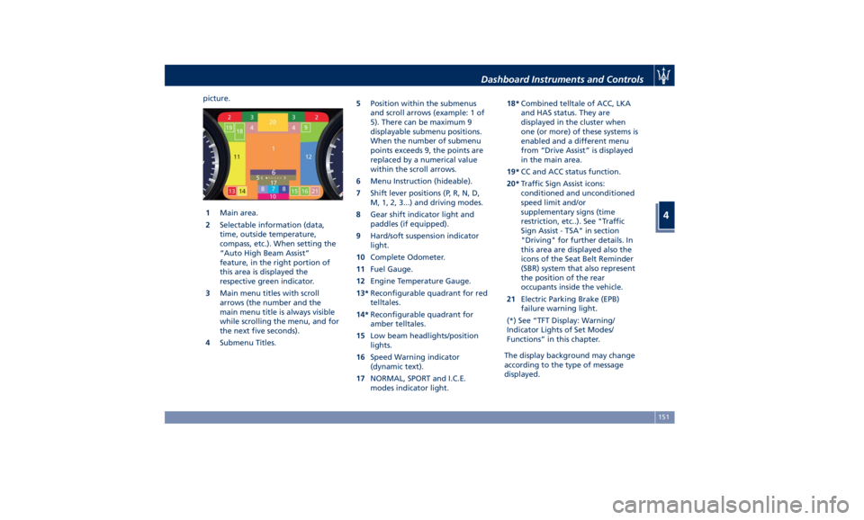
picture.
1 Main area.
2 Selectable information (data,
time, outside temperature,
compass, etc.). When setting the
“Auto High Beam Assist”
feature, in the right portion of
this area is displayed the
respective green indicator.
3 Main menu titles with scroll
arrows (the number and the
main menu title is always visible
while scrolling the menu, and for
the next five seconds).
4 Submenu Titles. 5 Position within the submenus
and scroll arrows (example: 1 of
5). There can be maximum 9
displayable submenu positions.
When the number of submenu
points exceeds 9, the points are
replaced by a numerical value
within the scroll arrows.
6 Menu Instruction (hideable).
7 Shift lever positions (P, R, N, D,
M, 1, 2, 3...) and driving modes.
8 Gear shift indicator light and
paddles (if equipped).
9 Hard/soft suspension indicator
light.
10 Complete Odometer.
11 Fuel Gauge.
12 Engine Temperature Gauge.
13* Reconfigurable quadrant for red
telltales.
14* Reconfigurable quadrant for
amber telltales.
15 Low beam headlights/position
lights.
16 Speed Warning indicator
(dynamic text).
17 NORMAL, SPORT and I.C.E.
modes indicator light. 18* Combined telltale of ACC, LKA
and HAS status. They are
displayed in the cluster when
one (or more) of these systems is
enabled and a different menu
from “Drive Assist” is displayed
in the main area.
19* CC and ACC status function.
20* Traffic Sign Assist icons:
conditioned and unconditioned
speed limit and/or
supplementary signs (time
restriction, etc..). See "Traffic
Sign Assist - TSA" in section
"Driving" for further details. In
this area are displayed also the
icons of the Seat Belt Reminder
(SBR) system that also represent
the position of the rear
occupants inside the vehicle.
21 Electric Parking Brake (EPB)
failure warning light.
(*) See “TFT Display: Warning/
Indicator Lights of Set Modes/
Functions” in this chapter.
The display background may change
according to the type of message
displayed.Dashboard Instruments and Controls
4
151
Page 212 of 384
Normal Starting of the
Engine WARNING!
It is dangerous to run the engine in an
enclosed area. The engine consumes
oxygen and discharges carbon
dioxide, carbon monoxide and other
toxic gases in the atmosphere.
WARNING!
California Proposition 65
Operating, servicing and maintaining
a passenger vehicle or off-road vehicle
can expose you to chemicals including
such as, engine exhaust, carbon
monoxide, phthalates and lead, that
which are known to the State of
California to cause cancer and birth
defects or other reproductive harm. To
minimize exposure, avoid breathing
exhaust, do not idle the engine except
as necessary, service your vehicle in a
well-ventilated area and wear gloves
or wash your hands frequently when
servicing your vehicle. For more
information go to: www.P65Warnings.ca.gov/passenger-
vehicle
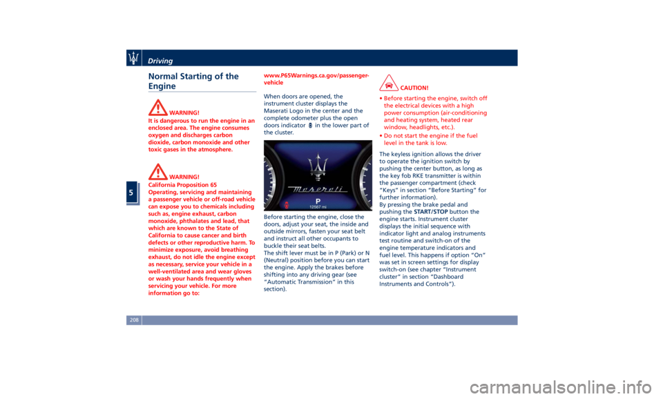
When doors are opened, the
instrument
cluster displays
the
Maserati Logo in the center and the
complete odometer plus the open
doors indicator
in the lower part of
the cluster.
Before starting the engine, close the
doors, adjust your seat, the inside and
outside mirrors, fasten your seat belt
and instruct all other occupants to
buckle their seat belts.
The shift lever must be in P (Park) or N
(Neutral) position before you can start
the engine. Apply the brakes before
shifting into any driving gear (see
“Automatic Transmission” in this
section). CAUTION!
• Before starting the engine, switch off
the electrical devices with a high
power consumption (air-conditioning
and heating system, heated rear
window, headlights, etc.).
• Do not start the engine if the fuel
level in the tank is low.
The keyless ignition allows the driver
to
operate the
ignition switch by
pushing the center button, as long as
the key fob RKE transmitter is within
the passenger compartment (check
“Keys” in section “Before Starting” for
further information).
By pressing the brake pedal and
pushing the START/STOP button the
engine starts. Instrument cluster
displays the initial sequence with
indicator light and analog instruments
test routine and switch-on of the
engine temperature indicators and
fuel level. This happens if option “On”
was set in screen settings for display
switch-on (see chapter “Instrument
cluster” in section “Dashboard
Instruments and Controls”).Driving
5
208
Page 215 of 384

Pressing the brake pedal and shifting
transmission into D (Drive) or R
(Reverse) will deactivate the
“AutoStop” condition and restart the
engine.
Start&Stop Deactivated Start&Stop function is deactivated
under the following conditions:
• When SPORT drive mode is activated.
• When
(ESC OFF) drive mode is
activated.
• If it has been disabled through the
main menu item “Start&Stop”, via
the controls located on the right side
of the steering wheel, or through
the Start & Stop hard button on the
central console (see chapter “Drive
Mode” in this section) or via the
MTC+ in the "Controls" page (see
“MTC+ “Controls” Screen” in section "Dashboard Instruments and
Controls") .
Start&Stop Not Active For keeping driving safety, interior
comfort and a correct functioning of
engine and vehicle, the Start&Stop
function does not activate under the
following conditions:
• When the driver’s seat belt is
unbuckled (see example).
• When the driver door is open.
• When the fuel level is too low.
• When the vehicle is stopped on a
very steep road.
• When the vehicle is stopped with
steered wheels (over 135° of steering
wheel angle for each part).
• When the vehicle is manoeuvring:
shift lever in R (Reverse). • When the temperature conditions
inside the vehicle do not correspond
to the air conditioning setting.
• When the front and rear “defroster”
function is activated.
• When the engine coolant and the
engine oil temperature are not on
proper functioning level.
• When the external temperature is
too cold.
• When the battery charge is below
safety value.
• When the previous stop had just
happened (few seconds) and the
minimum speed has not yet been
achieved.
• Shortly after R (Reverse) has been set
or when driving under a certain
speed level.
• When the hood is open.
• The sensors managing the
Start&Stop have been damaged.
• Start&Stop system faults are present.
• When Adaptive Cruise Control (ACC)
and/or Highway Assist (HAS) system
are engaged.
Automatic Restarting of the
Engine The engine may automatically restart,
before the brake pedal has beenDriving
5
211