transmission MASERATI GHIBLI 2019 Service Manual
[x] Cancel search | Manufacturer: MASERATI, Model Year: 2019, Model line: GHIBLI, Model: MASERATI GHIBLI 2019Pages: 384, PDF Size: 13.33 MB
Page 245 of 384
If the driver does not apply the
throttle during this short period of
time, the system will release brake
pressure and the vehicle will start
sloping down. The system will release
brake pressure proportionally to the
amount of throttle/torque applied as
the vehicle starts to move in the
chosen direction.
HSA Activation Criteria
The following criteria must be met in
order for HSA to activate:
• vehicle is stationary;
• gear selection matches vehicle uphill
direction (i.e., vehicle facing uphill is
in forward gear; vehicle backing
uphill is in reverse gear).
HSA will work in R (Reverse) and all
forward gears when the activation
criteria have been met.
The system will not activate if the
transmission is placed in N (Neutral) or
P (Park). Using the Brakes CAUTION!
To obtain a good performance by
brake pads and discs, avoid sudden
braking during the first 190 mi
(300 km).
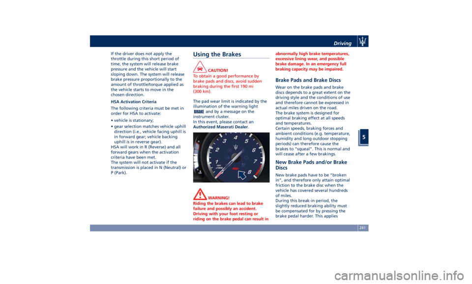
The pad wear limit is indicated by the
illumination
of the
warning light
and by a message on the
instrument cluster.
In this event, please contact an
Authorized Maserati Dealer .
WARNING!
Riding the brakes can lead to brake
failure and possibly an accident.
Driving with your foot resting or
riding on the brake pedal can result in abnormally high brake temperatures,
excessive lining wear, and possible
brake damage. In an emergency full
braking capacity may be impaired.
Brake Pads and Brake Discs Wear on the brake pads and brake
discs depends to a great extent on the
driving style and the conditions of use
and therefore cannot be expressed in
actual miles driven on the road.
The brake system is designed for
optimal braking effect at all speeds
and temperatures.
Certain speeds, braking forces and
ambient conditions (e.g. temperature,
humidity and long outdoor stopping
periods) can therefore cause the
brakes to "squeal". This is normal and
will cease after a few brakings.
New Brake Pads and/or Brake
Discs New brake pads have to be “broken
in”, and therefore only attain optimal
friction to the brake disc when the
vehicle has covered several hundreds
of miles.
During this break-in period, the
slightly reduced braking ability must
be compensated for by pressing the
brake pedal harder. This appliesDriving
5
241
Page 247 of 384
CAUTION!
• Under normal conditions, all red
warning lights on the instrument
cluster display should be off. When
they come on, this indicates a
malfunction. Refer to “Instrument
Cluster” in section “Dashboard
Instruments and Controls”.
• Continuing to drive when a red
warning light is on could cause
serious damage to the vehicle and
affect its performance.
Onboard Diagnostic System Your vehicle is equipped with a
sophisticated onboard diagnostic
system. This system monitors the
performance of the emissions, engine,
and automatic transmission control
systems. When these systems are
operating properly, your vehicle will
provide excellent performance and
fuel economy, as well as engine
emissions well within current local
regulations of various countries.
If any of these systems require service,
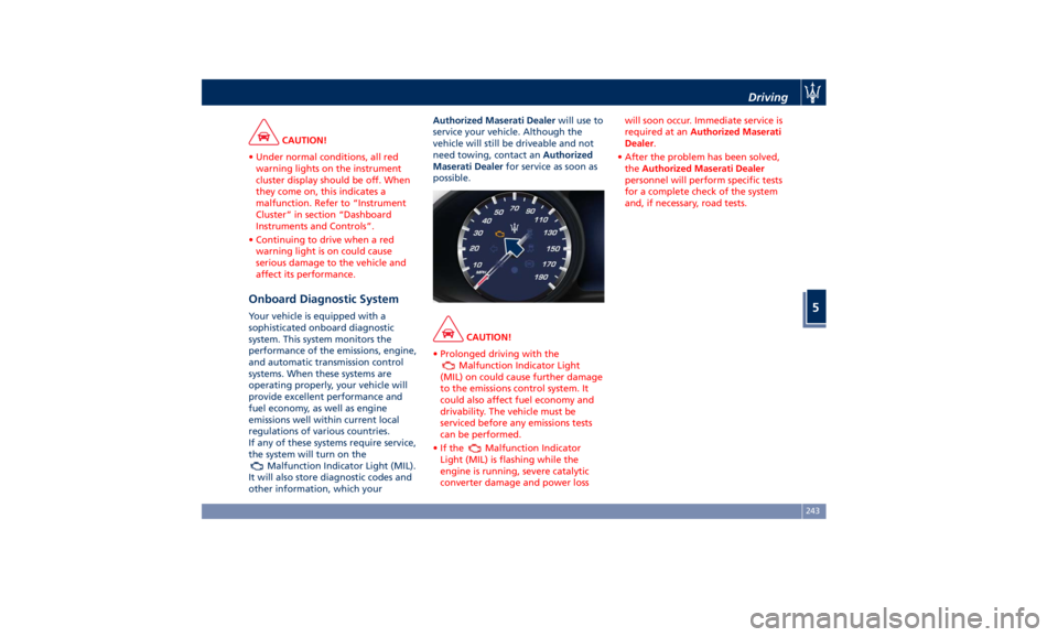
the system will turn on the
Malfunction Indicator Light (MIL).
It will also store diagnostic codes and
other information, which your Authorized Maserati Dealer will use to
service your vehicle. Although the
vehicle will still be driveable and not
need towing, contact an Authorized
Maserati Dealer for service as soon as
possible.
CAUTION!
• Prolonged driving with the
Malfunction Indicator Light
(MIL) on could cause further damage
to the emissions control system. It
could also affect fuel economy and
drivability. The vehicle must be
serviced before any emissions tests
can be performed.
•Ifthe
Malfunction Indicator
Light (MIL) is flashing while the
engine is running, severe catalytic
converter damage and power loss will soon occur. Immediate service is
required at an Authorized Maserati
Dealer .
• After the problem has been solved,
the Authorized Maserati Dealer
personnel will perform specific tests
for a complete check of the system
and, if necessary, road tests.Driving
5
243
Page 251 of 384
Driver Override If the driver presses the accelerator
pedal while the CC is on, such as to
overtake another vehicle, and exceeds
the set speed limit, the system will
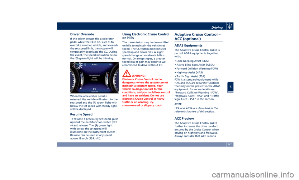
temporarily deactivate the CC. During
the event, the speed indication below
the
green light will be blinking.
When the accelerator pedal is
released, the vehicle will return to the
set speed and the
green light with
below the set speed with steady light
will be displayed.
Resume Speed To resume a previously set speed, push
upward the multifunction switch (RES
+) and release. The
green light
with below the set speed will
illuminate on the instrument cluster.
Resume can be used at any speed
above 18 mph (30 km/h). Using Electronic Cruise Control
on Hills The transmission may be downshifted
on hills to maintain the vehicle set
speed. The CC system maintains set
speed up and down hills. A slight
speed change on moderate hills is
normal. On steep slopes, a greater
speed loss or gain may occur so we
recommend to drive without CC.
WARNING!
Electronic Cruise Control can be
dangerous where the system cannot
maintain a constant speed. Your
vehicle could go too fast for the
conditions, and you could lose control
and have an accident. Do not use
electronic Cruise Control in heavy
traffic or on winding, icy,
snow-covered or slippery roads.Adaptive Cruise Control –
ACC (optional) ADAS Equipments The Adaptive Cruise Control (ACC) is
part of ADAS equipments together
with:
• Lane Keeping Assist (LKA)
• Active Blind Spot Assist (ABSA)
• Forward Collision Warning (FCW)
• Highway Assist (HAS)
• Traffic Sign Assist (TSA).
FCW is a standard equipment while
HAS and TSA are separate functions
that may not be present in the ADAS
equipment. For more details see
“Forward Collision Warning - FCW”,
“Highway Assist - HAS" and "Traffic
Sign Assist - TSA" in this section.
NOTE:
LKA and ABSA are described in the
relevant chapters of this section.
ACC Preview The Adaptive Cruise Control (ACC)
further increases the drive comfort
ensured by the Cruise Control when
driving on highways and freeways.
Always consider that ACC is not aDriving
5
247
Page 254 of 384
NOTE:
Any change made to tire dimensions
affects performance of Adaptive Cruise
Control and Front Collision Warning
(FCW), if equipped.
The ACC is not activated in the
following conditions:
• When braking.
• When parking brake is activated.
• When automatic transmission is in P
(Park), R (Reverse) or N (Neutral).
• When vehicle speed is out of preset
speed range
• When brakes are overheated.
• When driver door is open.
• When the driver’s seat belt is
unbuckled.
• When the road is particularly steep
(both uphill and downhill) at low
speed.
• When drive mode
(ESC OFF) is
selected.
• When the door is opened at low
speed.
• When there has been an ESC event in
the last 5 seconds, or is still active.
• When there is an object too close in
front of the vehicle.
It is possible that more than one
system is active at the same time such as ACC and ABSA just to mention
some.
While activation of ACC and CC at the
same time is impossible.
Speed Range of Use Speed mph (km/h)
Minimum 0 (0)
Engaged/activated 18 (30)
Maximum 130 (210)
Activation/Deactivation NOTE:
Pictures show status of ACC and LKA
systems.
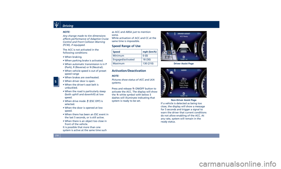
Press and release
ON/OFF button to
activate the ACC. The display will show
the
white symbol with below 3
dashes will illuminate indicating that
system is ready to be set.
If a vehicle is detected as being too
close, the display will show a message
for 5 seconds and trigger a signal to
warn the driver that current conditions
do not allow enabling of the ACC. At
any rate, system will remain in the
ready status. Driver Assist Page
Non-Driver Assist PageDriving
5
250
Page 256 of 384
(Continued)
• The ACC system applies the brake
down to a full stop when following a
target vehicle. If an ACC host vehicle
follows a target vehicle to a
standstill, after a two or three second
delay, the system will not be able to
resume driving the car
autonomously. At this point it is
necessary for the driver to manually
reengage the system by either using
the multifunction control (press SET-
or RES+) or by pressing the
accelerator pedal (see “ACC
Operation Before and During Stop”
in this chapter).
• The ACC system maintains set speed
when driving up hill and down hill.
However, a slight speed change on
moderate hills is normal. In addition,
downshifting may occur while
climbing uphill or descending
downhill. This is normal operation
and necessary to maintain set speed.
When driving uphill and downhill,
the ACC system will cancel if the
braking temperature exceeds normal
range.
Temporary Deactivation A soft tap on the brake pedal, pushing
the multifunction control (CANC), or normal brake pressure while slowing
the vehicle will temporarily deactivate
the ACC without erasing the set speed
memory. The
white light will appear
on the display with below the set
speed.
Conditions for Disabling and
Deactivation Besides the cases specified in the
previous paragraph, the following
conditions will disable the system:
• Anti-Lock Brake (ABS) kicks in.
• Transmission lever is not in D (Drive).
• The Electronic Stability Control and
the Traction Control System (ESC/TCS)
activate.
• Vehicle parking brake is operated.
• The driver safety belt is unbuckled at
low speed.
• The driver door is ajar at low speed.
• The driver disabled the ESC using the
(ESC OFF) button on central
console.
• The road is too steep both uphill and
downhill at low speed.
The system is deactivated and set
speed is deleted from system memory,
if the ACC ON/OFF button is pressed or
if ignition device is turned to OFF .Resuming Speed If a speed setting is stored in system
memory, press the multifunction
control (RES +) up and take foot off
the accelerator pedal. The last set
speed will be displayed.
WARNING!
The resume function should be used
only when road and traffic conditions
allow it. Resuming a too high or too
low speed for current traffic and road
conditions could cause a harsh vehicle
acceleration or deceleration which
could increase the risk of collisions
and death or serious injury.
Setting the ACC Gap The specified ACC gap can be set by
varying the distance setting among the
four possible options identified by the
number of horizontal bars:
• Maximum (longest) distance: 4 bars.
• Long distance: 3 bars (default
distance).
• Medium distance: 2 bars.
• Short distance: 1 bar.
Using this distance setting and the
vehicle speed, ACC calculates and sets
the gap to the vehicle ahead.Driving
5
252
Page 270 of 384

Blind Spot Assist (without
ACC) BSA System Operation The Blind Spot Assist (BSA) system uses
two radar-based sensors, located inside
the rear bumper fascia, to detect
highway licensable vehicles (cars,
buses, motorbikes, etc.) that enter the
blind spot zones from the
rear/front/side of the vehicle.
The example shown in the figure
highlights the blind spots on either
side of the vehicle when oncoming
traffic is approaching from behind.
When the vehicle is started, the BSA
warning light will momentarily
illuminate in both outside rear view
mirrors to let the driver know that the
system is operational and on. The BSA
system sensors operate when the vehicle is in any forward gear and
enters standby mode when the
transmission is in (P) Park.
The BSA detection zone shown in
figure covers approximately one lane
on both sides of the vehicle
(approximately 11 ft or 3.3 m). The
blind spot area extends from
immediately behind the exterior
rear-view mirrors up to about 23 ft (7
m) behind the rear bumper. The BSA system monitors the detection
zones on both sides of the vehicle
when the vehicle speed reaches
approximately 6 mph (10 km/h) or
higher and will alert the driver of
vehicles in these areas.
WARNING!
• The BSA system does NOT alert the
driver about rapidly approaching
vehicles that are outside the
detection zones.
• The BSA might alert the driver too
late especially in case of rapidly
approaching vehicles.
WARNING!
Risk of accident despite Blind Spot
Assist (BSA).
BSA does not detect/react to the
following:
• Overtaking vehicles close on the
side, placing them in the blind spot
area. As a result, BSA may neither
give warnings nor intervene in such
situations.Driving
5
266
Page 305 of 384
• Do not exceed 5 mph (8 km/h) when
driving through standing water. This
will minimize wave effects.
• Driving through standing water may
cause damage to your vehicle
drivetrain components. After driving
through standing water, do not drive
if you are not sure about drivetrain
condition. Such damage is not
covered by the New Vehicle
Warranty.
• Getting water inside your vehicle
engine can cause it to lock up and
stall out, and cause serious internal
damage to the engine. Such damage
is not covered by the New Vehicle
Warranty.
• After driving through standing
water always have the fluids (engine
oil, transmission oil, etc) checked for
contamination at an Authorized
Maserati Dealer .
WARNING!
• Driving through standing water
limits your vehicle traction
capabilities. Do not exceed 5 mph
(8 km/h) when driving through
standing water.
• Driving through standing water limits your vehicle braking
capabilities, which increases
stopping distances. Therefore, after
driving through standing water,
drive slowly and lightly press on the
brake pedal several times to
progressively dry the brakes discs
and pads.
• Getting water inside your vehicle
engine can cause it to lock up and
stall out.
• Failure to follow these warnings
may result in injuries that are
serious or fatal to you, your
passengers, and others around you. Driving
5
301
Page 307 of 384
6 – In an Emergency ToolKit .............................................. 304
Hazard Warning Flashers ................................. 305
In the Event of an Accident ............................... 305
In case of a Punctured Tire ................................ 306
Emergency Release of the Parking Brake ..................... 311
Transmission Manual Release of P (Park) Position ............... 312
Auxiliary Jump-Start Procedure ............................ 312
Towing a Disabled Vehicle ................................ 315
303
Page 309 of 384
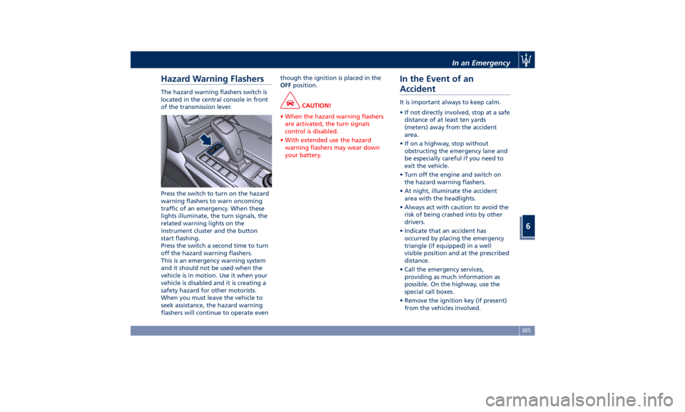
Hazard Warning Flashers The hazard warning flashers switch is
located in the central console in front
of the transmission lever.
Press the switch to turn on the hazard
warning flashers to warn oncoming
traffic of an emergency. When these
lights illuminate, the turn signals, the
related warning lights on the
instrument cluster and the button
start flashing.
Press the switch a second time to turn
off the hazard warning flashers.
This is an emergency warning system
and it should not be used when the
vehicle is in motion. Use it when your
vehicle is disabled and it is creating a
safety hazard for other motorists.
When you must leave the vehicle to
seek assistance, the hazard warning
flashers will continue to operate even though the ignition is placed in the
OFF position.
CAUTION!
• When the hazard warning flashers
are activated, the turn signals
control is disabled.
• With extended use the hazard
warning flashers may wear down
your battery.
In the Event of an
Accident It is important always to keep calm.
• If not directly involved, stop at a safe
distance of at least ten yards
(meters) away from the accident
area.
• If on a highway, stop without
obstructing the emergency lane and
be especially careful if you need to
exit the vehicle.
• Turn off the engine and switch on
the hazard warning flashers.
• At night, illuminate the accident
area with the headlights.
• Always act with caution to avoid the
risk of being crashed into by other
drivers.
• Indicate that an accident has
occurred by placing the emergency
triangle (if equipped) in a well
visible position and at the prescribed
distance.
• Call the emergency services,
providing as much information as
possible. On the highway, use the
special call boxes.
• Remove the ignition key (if present)
from the vehicles involved.In an Emergency
6
305
Page 316 of 384
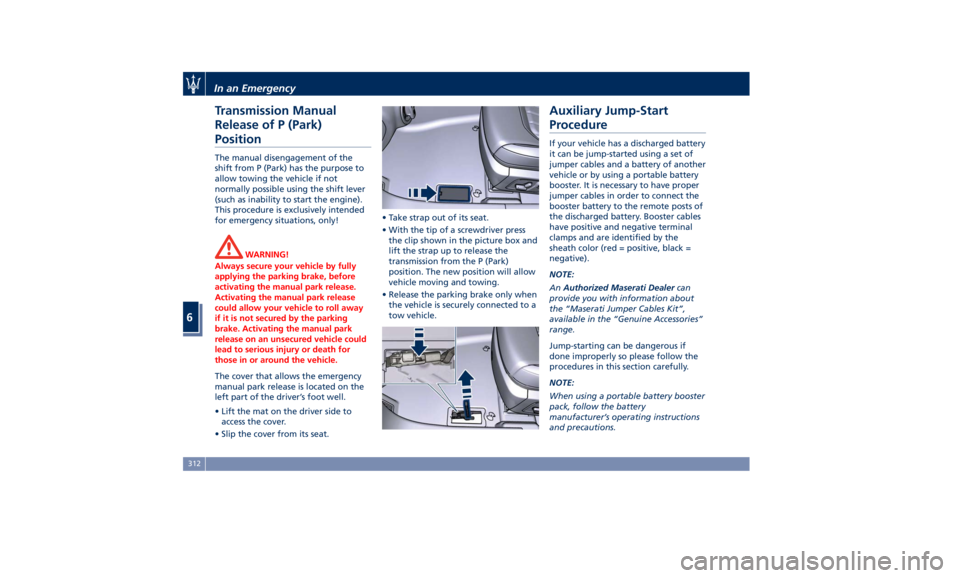
Transmission Manual
Release of P (Park)
Position The manual disengagement of the
shift from P (Park) has the purpose to
allow towing the vehicle if not
normally possible using the shift lever
(such as inability to start the engine).
This procedure is exclusively intended
for emergency situations, only!
WARNING!
Always secure your vehicle by fully
applying the parking brake, before
activating the manual park release.
Activating the manual park release
could allow your vehicle to roll away
if it is not secured by the parking
brake. Activating the manual park
release on an unsecured vehicle could
lead to serious injury or death for
those in or around the vehicle.
The cover that allows the emergency
manual
park release
is located on the
left part of the driver’s foot well.
• Lift the mat on the driver side to
access the cover.
• Slip the cover from its seat. • Take strap out of its seat.
• With the tip of a screwdriver press
the clip shown in the picture box and
lift the strap up to release the
transmission from the P (Park)
position. The new position will allow
vehicle moving and towing.
• Release the parking brake only when
the vehicle is securely connected to a
tow vehicle.Auxiliary Jump-Start
Procedure If your vehicle has a discharged battery
it can be jump-started using a set of
jumper cables and a battery of another
vehicle or by using a portable battery
booster. It is necessary to have proper
jumper cables in order to connect the
booster battery to the remote posts of
the discharged battery. Booster cables
have positive and negative terminal
clamps and are identified by the
sheath color (red = positive, black =
negative).
NOTE:
An Authorized Maserati Dealer can
provide you with information about
the “Maserati Jumper Cables Kit”,
available in the “Genuine Accessories”
range.
Jump-starting can be dangerous if
done improperly so please follow the
procedures in this section carefully.
NOTE:
When using a portable battery booster
pack, follow the battery
manufacturer’s operating instructions
and precautions.In an Emergency
6
312