ECO mode MASERATI GHIBLI 2019 Repair Manual
[x] Cancel search | Manufacturer: MASERATI, Model Year: 2019, Model line: GHIBLI, Model: MASERATI GHIBLI 2019Pages: 384, PDF Size: 13.33 MB
Page 252 of 384

safety system and is not designed to
prevent accidents.
The ACC allows driver to keep Cruise
Control active in limited or moderate
traffic conditions with no need to
constantly restore the Cruise Control.
The ACC uses a radar sensor, located
on the front grille behind the trident,
and the forward-facing camera behind
the internal rear-view mirror to detect
the presence of a vehicle ahead at a
close distance and moving in the same
direction.
This vehicle, in this chapter, will be
indicated as "target vehicle" or
"vehicle ahead".
NOTE:
• If the sensor detects no vehicle
ahead, the ACC system will maintain
set steady speed.
• If the ACC sensor detects a vehicle ahead, the ACC system automatically
kicks in by slightly accelerating or
braking (to avoid exceeding the
initially set speed) so that the vehicle
keeps present distance, trying to
adapt to the speed of the detected
vehicle ahead.
WARNING!
• The Adaptive Cruise Control (ACC) is
designed to increase vehicle driving
comfort. It must not be considered
as a means of replacing the required
attention of the driver. The driver is
always required to drive carefully.
The driver is always required to pay
utmost attention to driving
conditions (road, traffic, weather)
and style (speed, distance from
sensed vehicle ahead, brake use).
Driver has the full responsibility of
the vehicle therefore his attention is
crucial to keeping vehicle control, in
particular when approaching curves
and situations with heavy traffic.
Failure to follow these warnings can
result in a collision and death or
serious personal injury.
• In some driving scenarios, the ACC
could have detection problems. In
such cases, the ACC could kick in late or unexpectedly. The driver must be
careful since his/her intervention
could be necessary.
• It is always the driver’s responsibility
to obey speed limits and to keep
minimum legal distance to the
preceding vehicle.
• ACC system can decelerate only with
limited braking, it cannot execute
emergency braking.
The ACC system:
•
Does not activate/react in the
presence of pedestrians, bicycles,
incoming traffic from the opposite
direction and steady objects such as a
vehicle stuck in a traffic jam.
• Is meant for the use on highways and
well-built roads, not for city traffic or
mountain roads.
• May not have enough time to react
and/or decelerate sufficiently on
vehicles when lane is changed too
quickly or the relative speed is too
high. In such cases the driver has to
react appropriately and without any
acoustic/visual and warning.
• Cannot consider road, traffic and
weather conditions and might prove
limited when visibility is poor.
• Does not always fully recognize
complex driving conditions and thisDriving
5
248
Page 254 of 384
NOTE:
Any change made to tire dimensions
affects performance of Adaptive Cruise
Control and Front Collision Warning
(FCW), if equipped.
The ACC is not activated in the
following conditions:
• When braking.
• When parking brake is activated.
• When automatic transmission is in P
(Park), R (Reverse) or N (Neutral).
• When vehicle speed is out of preset
speed range
• When brakes are overheated.
• When driver door is open.
• When the driver’s seat belt is
unbuckled.
• When the road is particularly steep
(both uphill and downhill) at low
speed.
• When drive mode
(ESC OFF) is
selected.
• When the door is opened at low
speed.
• When there has been an ESC event in
the last 5 seconds, or is still active.
• When there is an object too close in
front of the vehicle.
It is possible that more than one
system is active at the same time such as ACC and ABSA just to mention
some.
While activation of ACC and CC at the
same time is impossible.
Speed Range of Use Speed mph (km/h)
Minimum 0 (0)
Engaged/activated 18 (30)
Maximum 130 (210)
Activation/Deactivation NOTE:
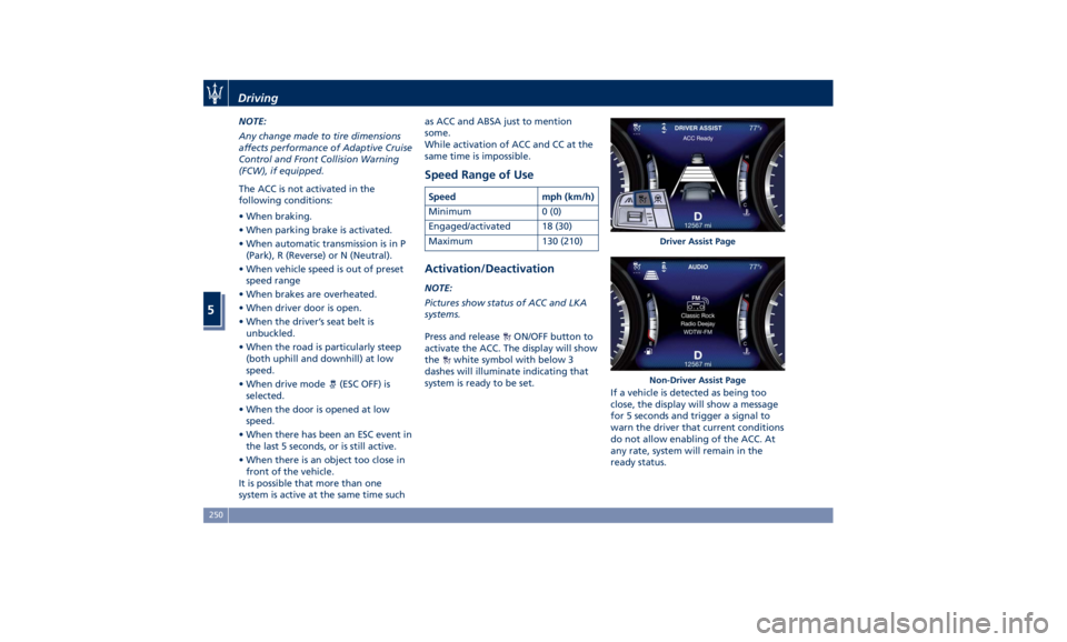
Pictures show status of ACC and LKA
systems.
Press and release
ON/OFF button to
activate the ACC. The display will show
the
white symbol with below 3
dashes will illuminate indicating that
system is ready to be set.
If a vehicle is detected as being too
close, the display will show a message
for 5 seconds and trigger a signal to
warn the driver that current conditions
do not allow enabling of the ACC. At
any rate, system will remain in the
ready status. Driver Assist Page
Non-Driver Assist PageDriving
5
250
Page 256 of 384
(Continued)
• The ACC system applies the brake
down to a full stop when following a
target vehicle. If an ACC host vehicle
follows a target vehicle to a
standstill, after a two or three second
delay, the system will not be able to
resume driving the car
autonomously. At this point it is
necessary for the driver to manually
reengage the system by either using
the multifunction control (press SET-
or RES+) or by pressing the
accelerator pedal (see “ACC
Operation Before and During Stop”
in this chapter).
• The ACC system maintains set speed
when driving up hill and down hill.
However, a slight speed change on
moderate hills is normal. In addition,
downshifting may occur while
climbing uphill or descending
downhill. This is normal operation
and necessary to maintain set speed.
When driving uphill and downhill,
the ACC system will cancel if the
braking temperature exceeds normal
range.
Temporary Deactivation A soft tap on the brake pedal, pushing
the multifunction control (CANC), or normal brake pressure while slowing
the vehicle will temporarily deactivate
the ACC without erasing the set speed
memory. The
white light will appear
on the display with below the set
speed.
Conditions for Disabling and
Deactivation Besides the cases specified in the
previous paragraph, the following
conditions will disable the system:
• Anti-Lock Brake (ABS) kicks in.
• Transmission lever is not in D (Drive).
• The Electronic Stability Control and
the Traction Control System (ESC/TCS)
activate.
• Vehicle parking brake is operated.
• The driver safety belt is unbuckled at
low speed.
• The driver door is ajar at low speed.
• The driver disabled the ESC using the
(ESC OFF) button on central
console.
• The road is too steep both uphill and
downhill at low speed.
The system is deactivated and set
speed is deleted from system memory,
if the ACC ON/OFF button is pressed or
if ignition device is turned to OFF .Resuming Speed If a speed setting is stored in system
memory, press the multifunction
control (RES +) up and take foot off
the accelerator pedal. The last set
speed will be displayed.
WARNING!
The resume function should be used
only when road and traffic conditions
allow it. Resuming a too high or too
low speed for current traffic and road
conditions could cause a harsh vehicle
acceleration or deceleration which
could increase the risk of collisions
and death or serious injury.
Setting the ACC Gap The specified ACC gap can be set by
varying the distance setting among the
four possible options identified by the
number of horizontal bars:
• Maximum (longest) distance: 4 bars.
• Long distance: 3 bars (default
distance).
• Medium distance: 2 bars.
• Short distance: 1 bar.
Using this distance setting and the
vehicle speed, ACC calculates and sets
the gap to the vehicle ahead.Driving
5
252
Page 267 of 384
System Availability The ADAS systems (LKA, CC, ACC, FCW
and HAS) help the driver while
driving. These systems can be set and
monitored simultaneously on the
display, after opening “Driver Assist”
menu (see paragraph “TFT Display:
Menus and Settings” under
“Instrument Cluster” in section
“Dashboard Instruments and
Controls”).
LKA is designed for an attentive
driver; therefore the system is
available only when his/her hands are
on the steering wheel or with hands
off for only a limited amount of time.
When the system is enabled it will
trigger cluster warning in case at least
one hand is not detected on the
steering wheel.
The torque application as well as the
vibration are suppressed/inhibited in
case of: high driver torque in the
steering wheel, high lateral
acceleration, hands not on the
steering wheel detected for more than
a certain time.
High dynamic driving behaviors,
driving on the lane boundary, or
driving off course will prevent the
function from working. FCW braking
and stability system interventions (ESC, ABS) will also prevent the system from
operating. Changing lanes results in
system inhibition for a certain time. In
addition, the driver must respect some
road characteristics such as
minimum-maximum width, lanes
clearly defined by two lane
boundaries and, only in limited cases
and for a limited time, at least one
lane boundary.
NOTE:
• In case of wet road or raining
conditions the function could be
disabled by the system in order to
minimize the risks.
• With lane boundaries it is mainly
referred to painted lines,
nevertheless the system in good
conditions might properly recognize
as valid lane boundaries also other
types (for example road edges,
curbs, etc..).
Being this function used to prevent
unintentional lane change/lane drift,
it will be temporary suppressed/
inhibited by a turn indicator
activation, therefore, graphic warning,
steering torque application and
vibration will be terminated. In this
condition in case of a vehicle detected
by the Blind Spot Assist (BSA) system in the covered area on the proper
side, there can be the transition from
LKA to Active Blind Spot Assist (ABSA)
(if this latter is on and properly
configured).
Function Description and
Operating Mode The intent of the function is to
prevent the lane departure by
warning the driver through indication
on the cluster and, if set, applying
steering torque and vibration.
Whenever the system is enabled there
will be graphic on the dedicated
screen in the driver assist page and for
the others it will be available in the
left top corner of the cluster screen.
The graphic which intent is to
represent at the glance the system
knowledge of the lane in front of the
car, the system suppression status and
warning.
For this reason, a simple colour code
has been adopted for each line (of the
two presented):
• Both grey lines means system is
enabled, not able to operate
(suppression condition present or
lane detection system not able to
properly estimate the lane);Driving
5
263
Page 274 of 384

If the turn signal is then activated, and
it corresponds to an alert present on
that side of the vehicle, an audible
chime will also be sounded: in the
same moment the warning light will
start flashing.
Whenever a turn signal and detected
vehicle or object are present on the
same side at the same time, both the
visual and audio alerts will be issued.
In addition to the audible alert, the
radio volume will be reduced (if the
radio is on).
NOTE:
If the hazard flashers are on, the BSA
system will issue the appropriate visual
alert only.
When the system is in RCP mode, the
system shall respond with both visual
and audible alerts when a detected
vehicle or object is present. Whenever an audible alert is requested, the radio
(if on) is also muted.
Right/left turn/hazard signal status is
ignored; the RCP status always
requests the chime.
Blind Spot Assist Off
When this function is turned off from
the MTC+, there will be no visual or
audible alerts from either the BSA or
RCP subsystems.
NOTE:
The BSA system will store the current
operating mode when the vehicle is
shut off. Each time the vehicle is
started, the previously-stored mode
will be recalled and used.
System Temporarily Unavailable
The blind spot system will become
temporarily unavailable and the
instrument cluster display will show
the message “Blind Spot Alert
Temporarily Unavailable” when the
vehicle enters a radio quite zone
(example the areas around radio
telescopes).
The warning light on the outside
rear-view mirrors will be lit up and stay
lit until the vehicle exits the zone. System is Faulty
The BSA system cannot properly
operate due to a fault of its
components, or because the area on
the rear bumper fascia where the
radar sensors are located is dirty. In
these cases the amber warning light
and the related message will be
displayed on the instrument cluster.
In these cases do not use the system
and have the vehicle inspected at an
Authorized Maserati Dealer .
Radar Device - Regulatory
Information The “Regulatory Information” for all
the radio frequency and radar devices
can be consulted by accessing the
“Services” section on the website
www.maserati.com.Driving
5
270
Page 277 of 384

• ABSA “Strength": it tunes the
steering torque value to have a
stronger or weaker directional
correction/deviation.
Blind Spot Assist in "Visual & Haptic"
Mode
When the system is on and configured
“Visual & Haptic” then the ABSA is
enabled and to the conventional
visual warnings is added the steering
torque and vibration.
When operating in this mode, the
system will provide a visual alert in the
appropriate outside rear-view mirror
when it detects a vehicle or an object
in the detection areas monitored by its
sensors. In case of turn indicator
activation on the appropriate side, the
system will react with a torque on the
steering wheel to try to prevent the
lane change and therefore to
avoid/mitigate the collision. The
torque on the steering is applied
when the car is very close to the lane
boundary as a further feedback to
warn the driver of the unsafe
maneuver.
NOTE:
• The steering torque is not supplied if
the system is not able to estimate a
lane and if the turn indicator from
the appropriate side is not inserted. • The presence of the hands on the
steering wheel is detected by a logic
combination of a capacitive sensor
installed in the steering wheel and
the measured applied torque at the
steering column. This leads to a
more robust hands detection.
WARNING!
• Risk of accident despite steering
torque application of Active Blind
Spot Assist (ABSA).
• A course-correcting steering torque
application cannot always prevent a
collision.
• The driver is always required to
steer, brake or accelerate themself,
especially if ABSA warns or makes a
course correcting steer intervention.
• Always maintain a safe distance at
the sides.
• Steering torque application may be
interrupted at any time by counter
steering by the driver.
RCP - Rear Cross Path
Operation RCP operation is the same as described
in chapter "Blind Spot Assist - BSA". When ABSA is turned off from MTC+
"Controls" page, there will be no
visual or audible alerts from RCP
subsystem.
When ABSA is turned on with any
setting,RCP subsystem shall respond
with both visual and audible alerts
when a detected vehicle or object is
present. Whenever an audible alert is
requested, the radio (if on) is also
muted.
Right/left turn/hazard signal status is
ignored; the RCP status always
requests the chime.
System Temporarily
Unavailable The blind spot system will become
temporarily unavailable and the
instrument cluster display will show
the message “Blind Spot Alert
Temporarily Unavailable” when the
vehicle enters a radio quite zone
(example the areas around radio
telescopes).
The warning light on the outside
rear-view mirrors will be lit up and
stay lit until the vehicle exits the zone.
System Fault The ABSA system cannot properly
operate either due to a fault of its
components, or because the area onDriving
5
273
Page 291 of 384

overall conditions should also be
checked monthly. Tire pressures
change by approximately 1 PSI (0.07
bar) per 12°F (7°C) of air temperature
change. Keep this in mind when
checking tire pressure inside a garage,
especially in winter.
Example: If garage temperature = 68°F
(20°C) and the outside temperature =
32°F (0°C) then the cold tire inflation
pressure should be increased by 3 PSI
(0.21 bar) for every 12°F (7°C) for this
outside temperature condition.
Tire pressure may increase from 2 to 6
PSI (0.13 to 0.4 bar) during operation.
DO NOT reduce this normal pressure
build-up or your tire pressure will be
too low. After inspecting or adjusting
the tire pressure, always reinstall the
valve stem cap. This will prevent
moisture and dirt from entering the
valve stem, which could damage the
valve stem and the TPMS sensor
connected to it.
Tread Wear Indicators Tread wear indicators are in the
original equipment tires to help you
determine when your tires should be
replaced.
These indicators are molded into the
bottom of the tread grooves. When the tread is worn to one of the
tread wear indicators, the tire should
be replaced.
WARNING!
The wet performance (aquaplaning
resistance) will decrease
proportionally to the thickness of the
tread.
Tires Durability The service life of a tire depends on
various factors including, but not
limited to:
• driving style;
• tire pressure;
• distance driven.
WARNING!
Tires and the spare tire (if equipped)
should be replaced after six years,
regardless of the remaining tread.
Failure to follow this warning could
result in tire failure. Replacement Tires NOTE:
In order to maintain high performance
and safety level under all driving
conditions, Maserati strongly
recommends to use tires equivalent to
the originals in size, quality and
performance when replacement is
needed.
For the size designation of your tire
see the label on the driver's side rear
door pillar or see table “Wheels” in
section “Features and Specifications”.
The “Load Index” and “Speed
Symbol” for your tire will be found on
the original equipment tire sidewall.
NOTE:
Maserati recommends Maserati
Genuine Tires marked with “MGT”
logo specifically designed for its
models.
It is recommended to replace the two
front tires or two rear tires as a pair.
Replacing just one tire can seriously
affect your vehicle’s handling.
If you ever replace a wheel assembly,
make sure that the wheel’s
specifications (valve, TPMS sensor and
tire) match those of the original
wheels. Failure to use equivalentDriving
5
287
Page 293 of 384
The chains may be fitted only on 18”
and 19” rear wheel tires.
Please contact an Authorized Maserati
Dealer for further information.
Check the snow chain tension after
driving for a distance of about 55 yd
(50 m) with the chains fitted.
With the snow chains fitted, it is
advisable to deactivate the ESC system
(see chapter “Drive Mode” in this
section).
CAUTION!
• The use of non-recommended snow
chains may damage the vehicle.
• Broken snow chains can cause
serious damage. Stop the vehicle
immediately if noise occurs that
could indicate snow chain breakage.
Replace the damaged parts of the
snow chain before further use.
• Do not exceed 30 mph (50 km/h).
• Drive cautiously and avoid severe
turns and large bumps, especially
with a loaded vehicle.
• Avoid holes in the road, do not drive
over steps or sidewalks and do not
drive on long stretches without
snow. This will prevent damage to
the vehicle and the roadbed. NOTE:
The Authorized
Maserati Dealer can
provide you with all information
about the Maserati Snow Chains,
available in the "Genuine Accessories"
range.
Compact Spare Tire The limited-use spare tire, or compact
spare tire, is for temporary emergency
use only. This tire is identified by a
label indicating the driving speed
limitations to comply with when using
the spare tire.
Inflate the spare tire to the cold
inflation pressure listed on the table
“Tire Inflation Pressure” in section
“Features and Specifications”.
Mounting the spare tire affects vehicle
handling. Replace (or repair) as soon
as possible the original equipment tire
and reinstall it on the vehicle. Do not
install more than one compact spare
tire and wheel on the vehicle at a
time.
WARNING!
With these compact spare tires, do not
drive more than 50 mph (80 km/h).
Temporary use spares have limited
tread life.Tire Pressure Monitoring
System (TPMS) The Tire Pressure Monitoring System
(TPMS) will warn the driver of a low
tire pressure according to the vehicle
recommended cold pressure indicated
on the table “Tire Inflation Pressure”
in section “Features and
Specifications” and on the label
applied on the driver's side rear door
pillar.
Tire pressure should always be set
based on cold inflation tire pressure.
The cold tire inflation pressure must
not exceed the maximum inflation
pressure molded into the tire sidewall.
Check “Tires – General Information” in
section “Driving” for information on
how to properly inflate the tires.
The tire pressure will also increase as
the vehicle is driven - this is normal
and there is no adjustment required
when this occurs.
The TPMS will warn the driver of a low
tire pressure if the tire pressure falls
below the low-pressure warning limit
for any reason, including low
temperature effects and natural
pressure loss of the tire.
The TPMS will continue to warn the
driver of low tire pressure as long as
the condition persists and will not turnDriving
5
289
Page 304 of 384
CAUTION!
Be aware that rear fog lights can
bother the drivers following your
vehicle: when visibility is back to
normal, turn off these lights.
Driving in the Mountains
Mountain
roads usually
have many
narrow turns and curves, tunnels and
steep uphill or downhill slopes: please
consider some advices listed below.
• Drive at a moderate speed, avoid
“cutting” corners.
• When driving inside a tunnel in
daylight turn on the low beams in
advance; avoid high beams and be
aware of the rapid brightness
change. Avoid abrupt maneuvers
that could be dangerous for the
following vehicle.
• Never coast downhill with the engine
off or in neutral.
• Remember that passing other
vehicles when driving uphill is slower
and thus requires more free distance
on the road. If you are being
overtaken on a hill, slow down and
allow the other vehicle to pass. Driving on Snow or Ice
Please consider some general advice
for driving in these conditions, listed
below.
• Maintain a very moderate speed.
• Fit snow chains or specific tires if the
road is covered with snow: see the
paragraphs “Tires – General
Information” in this section.
• We recommend you to activate the
“I.C.E.” mode (see chapters “Drive
Mode” in this section).
• During the winter season, even
apparently dry roads can have icy
sections. Be careful when crossing
bridges, viaducts and roads that have
little exposure to the sun and are
bordered by trees and rocks. They
may be icy.
• Keep an ample safe distance from
the vehicles in front of you.
WARNING!
• Rapid acceleration on slippery
surfaces is dangerous. Unequal
traction can cause sudden pulling of
the driving wheels. You could lose
control of the vehicle and possibly
have a collision. Accelerate slowly
and carefully whenever there is likely to be poor traction (ice, snow,
wet mud, loose sand, etc.).
• Do not drive on or across a road or
path where water is flowing and/or
rising (as in storm run-off). Flowing
water can wear away the road or
path surface and cause your vehicle
to sink into deeper water.
Furthermore, flowing and/or rising
water can carry your vehicle away
swiftly. Failure to follow this
warning may result in injuries that
are serious or fatal to you, your
passengers, and others around you.
Although your vehicle is capable of
driving
through shallow standing
water, consider the following Cautions
and Warnings before doing so.
CAUTION!
• Always check the depth of the
standing water before driving
through it. Never drive through
standing water that is deeper than
47 in (150 mm).
• Determine the condition of the road
or the path that is under water and if
there are any obstacles in the way
before driving through the standing
water.Driving
5
300
Page 323 of 384
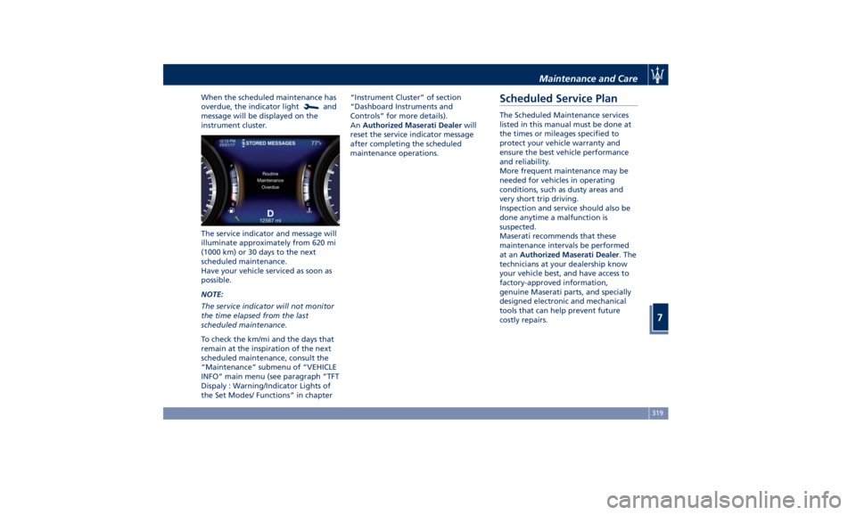
When the scheduled maintenance has
overdue, the indicator light
and
message will be displayed on the
instrument cluster.
The service indicator and message will
illuminate approximately from 620 mi
(1000 km) or 30 days to the next
scheduled maintenance.
Have your vehicle serviced as soon as
possible.
NOTE:
The service indicator will not monitor
the time elapsed from the last
scheduled maintenance.
To check the km/mi and the days that
remain at the inspiration of the next
scheduled maintenance, consult the
“Maintenance” submenu of “VEHICLE
INFO” main menu (see paragraph ”TFT
Dispaly : Warning/Indicator Lights of
the Set Modes/ Functions” in chapter “Instrument Cluster” of section
“Dashboard Instruments and
Controls” for more details).
An Authorized Maserati Dealer will
reset the service indicator message
after completing the scheduled
maintenance operations.
Scheduled Service Plan The Scheduled Maintenance services
listed in this manual must be done at
the times or mileages specified to
protect your vehicle warranty and
ensure the best vehicle performance
and reliability.
More frequent maintenance may be
needed for vehicles in operating
conditions, such as dusty areas and
very short trip driving.
Inspection and service should also be
done anytime a malfunction is
suspected.
Maserati recommends that these
maintenance intervals be performed
at an Authorized Maserati Dealer . The
technicians at your dealership know
your vehicle best, and have access to
factory-approved information,
genuine Maserati parts, and specially
designed electronic and mechanical
tools that can help prevent future
costly repairs.Maintenance and Care
7
319