ignition MASERATI GHIBLI 2019 Manual PDF
[x] Cancel search | Manufacturer: MASERATI, Model Year: 2019, Model line: GHIBLI, Model: MASERATI GHIBLI 2019Pages: 384, PDF Size: 13.33 MB
Page 256 of 384
(Continued)
• The ACC system applies the brake
down to a full stop when following a
target vehicle. If an ACC host vehicle
follows a target vehicle to a
standstill, after a two or three second
delay, the system will not be able to
resume driving the car
autonomously. At this point it is
necessary for the driver to manually
reengage the system by either using
the multifunction control (press SET-
or RES+) or by pressing the
accelerator pedal (see “ACC
Operation Before and During Stop”
in this chapter).
• The ACC system maintains set speed
when driving up hill and down hill.
However, a slight speed change on
moderate hills is normal. In addition,
downshifting may occur while
climbing uphill or descending
downhill. This is normal operation
and necessary to maintain set speed.
When driving uphill and downhill,
the ACC system will cancel if the
braking temperature exceeds normal
range.
Temporary Deactivation A soft tap on the brake pedal, pushing
the multifunction control (CANC), or normal brake pressure while slowing
the vehicle will temporarily deactivate
the ACC without erasing the set speed
memory. The
white light will appear
on the display with below the set
speed.
Conditions for Disabling and
Deactivation Besides the cases specified in the
previous paragraph, the following
conditions will disable the system:
• Anti-Lock Brake (ABS) kicks in.
• Transmission lever is not in D (Drive).
• The Electronic Stability Control and
the Traction Control System (ESC/TCS)
activate.
• Vehicle parking brake is operated.
• The driver safety belt is unbuckled at
low speed.
• The driver door is ajar at low speed.
• The driver disabled the ESC using the
(ESC OFF) button on central
console.
• The road is too steep both uphill and
downhill at low speed.
The system is deactivated and set
speed is deleted from system memory,
if the ACC ON/OFF button is pressed or
if ignition device is turned to OFF .Resuming Speed If a speed setting is stored in system
memory, press the multifunction
control (RES +) up and take foot off
the accelerator pedal. The last set
speed will be displayed.
WARNING!
The resume function should be used
only when road and traffic conditions
allow it. Resuming a too high or too
low speed for current traffic and road
conditions could cause a harsh vehicle
acceleration or deceleration which
could increase the risk of collisions
and death or serious injury.
Setting the ACC Gap The specified ACC gap can be set by
varying the distance setting among the
four possible options identified by the
number of horizontal bars:
• Maximum (longest) distance: 4 bars.
• Long distance: 3 bars (default
distance).
• Medium distance: 2 bars.
• Short distance: 1 bar.
Using this distance setting and the
vehicle speed, ACC calculates and sets
the gap to the vehicle ahead.Driving
5
252
Page 264 of 384
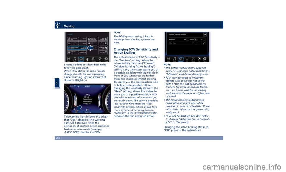
Setting options are described in the
following paragraph.
When FCW status for some reason
changes to off, the corresponding
amber warning light on instrument
cluster will light on.
This warning light informs the driver
that FCW is disabled. This warning
light will light even when the
activation of another driver assistance
feature or drive mode (example:
(ESC OFF)) disables the FCW. NOTE:
The FCW system setting is kept in
memory from one key cycle to the
next.
Changing FCW Sensitivity and
Active Braking The default status of FCW Sensitivity is
the “Medium” setting. When the
active braking function (“Forward
Collision Warning Active Braking”)
setting is on, the system warns you of
a possible collision with the vehicle in
front of you when you are farther
away and it applies limited braking.
This gives you the most reaction time
to help avoid a possible collision.
Changing the sensitivity status to the
“Near” setting, allows the system to
warn you of a possible collision with
the vehicle in front of you when you
are much closer. This setting provides
less reaction time than the “Far”
sensitivity setting, which allows for a
more dynamic driving experience.
“Medium” is the intermediate status
between the two described above. NOTE:
• The default values shall appear at
every new ignition cycle: Sensitivity =
“Medium” and Active Braking = on.
• FCW may not react to irrelevant
objects such as objects not in the
path of the car, stationary objects
that are far away, oncoming traffic,
on cross traffic vehicles, or leading
vehicles with the same or higher rate
of speed.
• The active braking (autonomous
braking/braking aid) will not be
provided in case of potential collision
with static object such as guard rails,
walls, etc..).
• FCW will be disabled like ACC (refer
to chapter “Adaptive Cruise Control -
ACC” in this section.
Changing the active braking status to
“Off” prevents the system fromDriving
5
260
Page 295 of 384

will monitor the actual tire pressure
in the tire.
Premium System The TPMS system uses wireless
technology with wheel rim mounted
electronic sensors to monitor tire
pressure levels. Sensors mounted to
each wheel as part of the valve stem
transmit tire pressure readings to the
receiver module.
The TPMS consists of the following
components:
• receiver module;
• four TPMS sensors;
• various TPMS messages, which
display on the instrument cluster;
• warning light
.
Tire Pressure Low Warning
The TPMS light will illuminate in
the instrument cluster and an acoustic
signal will notify that tire pressure is
low in one or more of the four tires. The instrument cluster will also display
a screenshot reporting the pressure
values of each tire with flashing low
pressure value.
Should this occur, you should stop as
soon as possible and inflate the tire/s
with the low pressure (the one/s
flashing in the instrument cluster
graphic) to the recommended cold
pressure inflation value. Once the
system receives the updated tire
pressure value, the system will automatically update, the graphic
display in the instrument cluster will
stop flashing, and the TPMS light
will turn off. The vehicle may need
to be driven for up to 20 minutes
above 15 mph (24 km/h) in order for
the TPMS to acquire and process the
updated information.
Tire Pressure System Fault
If a system fault is detected, the TPMS
light
will flash for 75 seconds and
then remain lit followed by a beeping
sound. Therewith, the instrument
cluster will display a "Service Tire
Pressure System" message for a
minimum of five seconds and then
display dashes (--) in place of the
pressure value to indicate which
sensor is ineffective.
If the ignition switch is cycled, the
sequence will repeat, in case the
system fault still persists. If the system
fault no longer exists, the TPMS light
will no longer flash, and the
"Service Tire Pressure System"
message will no longer be displayed,
and a pressure value will be displayed
in place of the dashes.
A system fault can occur due to any of
the following:
• Signal interference due to electronic
devices or driving next to facilitiesDriving
5
291
Page 296 of 384
emitting the same radio frequencies
as the TPMS sensors.
• Installing aftermarket window
tinting that contains materials that
may block radio wave signals.
• Accumulation of snow or ice around
the wheels or wheel housings.
• Using tire chains on the vehicle.
• Using wheels/tires not equipped with
TPMS sensors.
The instrument cluster will also display
a "Service Tire Pressure System"
message for a minimum of five
seconds when a system fault related to
an incorrect sensor location fault is
detected. In this case, the "Service Tire
Pressure System" message is then
followed by a graphic display with
pressure values still shown. This
indicates that the pressure values are
still being received from the TPMS
sensors but they may not be located in
the correct vehicle position. The system
still needs to be serviced as long as the
"Service Tire Pressure System" message
is displayed. Vehicles with Compact Spare Tire
• The compact spare tire does not have
a TPMS sensor. Therefore, the TPMS
will not monitor the pressure of the
compact spare tire.
• If you replace a tire having pressure
below the low-pressure warning
limit, with the compact spare tire, on
the next ignition switch cycle, the
TPMS light
will illuminate
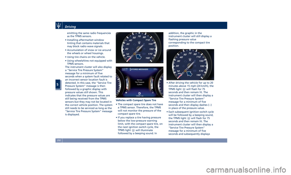
followed by a beeping sound. In addition, the graphic in the
instrument cluster will still display a
flashing pressure value
corresponding to the compact tire
position.
• After driving the vehicle for up to 20
minutes above 15 mph (24 km/h), the
TPMS light
will flash for 75
seconds and then remain lit. The
instrument cluster will then display a
"Service Tire Pressure System"
message for a minimum of five
seconds and then display dashes (--)
in place of the pressure value.
• Each subsequent ignition switch cycle
will be followed by a beeping sound,
the TPMS light
will flash for 75
seconds and then remain lit. The
instrument cluster will then display a
"Service Tire Pressure System"
message for a minimum of five
seconds and subsequently displaysDriving
5
292
Page 297 of 384

dashes (--) in place of the pressure
value.
• Once you repair, replace or reinstall
a tire with the compact spare tire,
the TPMS will update automatically.
The TPMS light
will turn OFF and
the graphic in the instrument cluster
will display a new pressure value
instead of dashes (--), as long as no
tire pressure is below the
low-pressure warning limit in any of
the four tires. The vehicle may need
to be driven for up to 20 minutes
above 15 mph (24 km/h) in order for
the TPMS to acquire and process the
updated information.
TPMS Deactivation The TPMS can be deactivated if
replacing all four tire rims with wheel
and tire assemblies not using of TPMS
sensors, such as winter wheel and tire assemblies. After replacing all four
wheel and tire assemblies (road tires)
with tires not equipped with Tire
Pressure Monitoring System sensors,
drive the vehicle for 20 minutes above
15 mph (24 km/h). The TPMS will
chime, the TPMS light
will flash on
and off for 75 seconds and then
remain on and the instrument cluster
will display the “Service Tire Pressure
System” message and then display
dashes (--) in place of the pressure
values. Beginning with the next
ignition switch cycle, the TPMS will no
longer chime or display the “Service
Tire Pressure System” message in the
instrument cluster but dashes (--) will
remain in place of the pressure values.
To reactivate the TPMS, replace all
four wheel and tire assemblies (road
tires) with tires equipped with TPMS
sensors. Then, drive the vehicle for up to 20 minutes above 15 mph
(24 km/h). The TPMS will chime, the
TPMS light
will flash for 75 seconds
and then turn off. The instrument
cluster will then display the “Service
Tire Pressure System” message.
The instrument cluster will also display
pressure values in place of the dashes
(--). On the next ignition switch cycle
the “Service Tire Pressure System”
message will no longer be displayed as
long as no system fault exists.
Radio Frequency Transmitter -
Regulatory Information The “Regulatory Information” for all
the radio and radar frequency devices
can be consulted by accessing the
“Services” section on the website
www.maserati.com.Driving
5
293
Page 309 of 384
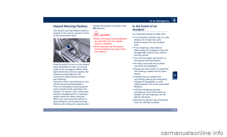
Hazard Warning Flashers The hazard warning flashers switch is
located in the central console in front
of the transmission lever.
Press the switch to turn on the hazard
warning flashers to warn oncoming
traffic of an emergency. When these
lights illuminate, the turn signals, the
related warning lights on the
instrument cluster and the button
start flashing.
Press the switch a second time to turn
off the hazard warning flashers.
This is an emergency warning system
and it should not be used when the
vehicle is in motion. Use it when your
vehicle is disabled and it is creating a
safety hazard for other motorists.
When you must leave the vehicle to
seek assistance, the hazard warning
flashers will continue to operate even though the ignition is placed in the
OFF position.
CAUTION!
• When the hazard warning flashers
are activated, the turn signals
control is disabled.
• With extended use the hazard
warning flashers may wear down
your battery.
In the Event of an
Accident It is important always to keep calm.
• If not directly involved, stop at a safe
distance of at least ten yards
(meters) away from the accident
area.
• If on a highway, stop without
obstructing the emergency lane and
be especially careful if you need to
exit the vehicle.
• Turn off the engine and switch on
the hazard warning flashers.
• At night, illuminate the accident
area with the headlights.
• Always act with caution to avoid the
risk of being crashed into by other
drivers.
• Indicate that an accident has
occurred by placing the emergency
triangle (if equipped) in a well
visible position and at the prescribed
distance.
• Call the emergency services,
providing as much information as
possible. On the highway, use the
special call boxes.
• Remove the ignition key (if present)
from the vehicles involved.In an Emergency
6
305
Page 310 of 384
• If fuel or other chemical products can
be smelled, do not smoke and ask
people around you to put their
cigarettes out.
• To extinguish fires, even small ones,
use a fire extinguisher, blankets, sand
or earth. Never use water.
• In multiple accidents occurred on
highways, particularly where visibility
is poor, there is a high risk of being
involved in other collisions. Leave the
vehicle immediately and move away
from the area.
In case of Injured Persons • Never leave the injured person alone.
Persons not directly involved in the
accident are also required to give
assistance.
• Do not crowd around injured
persons.
• Reassure the injured person that help
is on the way.
WARNING!
California Proposition 65
Operating, servicing and maintaining
a passenger vehicle or off-road vehicle
can expose you to chemicals including
such as, engine exhaust, carbon
monoxide, phthalates and lead, that which are known to the State of
California to cause cancer and birth
defects or other reproductive harm. To
minimize exposure, avoid breathing
exhaust, do not idle the engine except
as necessary, service your vehicle in a
well-ventilated area and wear gloves
or wash your hands frequently when
servicing your vehicle. For more
information go to:
www.P65Warnings.ca.gov/passenger-
vehicle
In case of a Punctured Tire If the vehicle is equipped with a
compact spare wheel.
Using the Compact Spare
Wheel NOTE:
The compact spare wheel is supplied in
aluminium or steel: the pictures show
the one in aluminium.
The compact spare wheel is stored in
the trunk and is supplied deflated in
order to limit the amount of space
occupied. An electric compressor is also
provided for inflating. In the event of
a tire puncture, proceed as follows.
• Stop the vehicle in a place that does
not constitute a danger to traffic and
where the wheel can be changed
safely.
• Select the P (Park) mode and then
engage manually the electric parking
brake and move the ignition switch
to OFF position.
• If necessary, turn the hazard warning
flashers on and place the warning
triangle (if equipped) at the required
distance.In an Emergency
6
306
Page 311 of 384
• If provided, the chock can be
installed in order to improve vehicle
stability.
WARNING!
The vehicle must be level and on the
firm ground during the vehicle lifting
operations. If forced to stop the
vehicle on a slope, call the Assistance
service and avoid any operation.
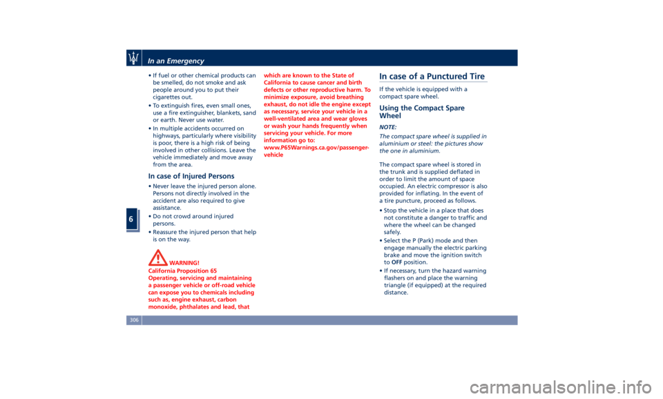
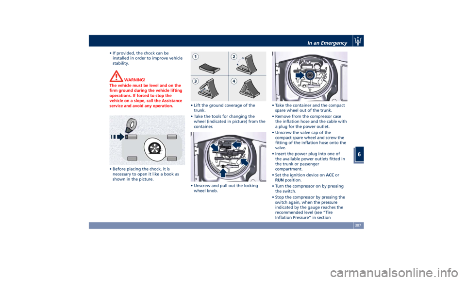
• Before placing the chock, it is
necessary
to open
it like a book as
shown in the picture. • Lift the ground coverage of the
trunk.
• Take the tools for changing the
wheel (indicated in picture) from the
container.
• Unscrew and pull out the locking
wheel knob. • Take the container and the compact
spare wheel out of the trunk.
• Remove from the compressor case
the inflation hose and the cable with
a plug for the power outlet.
• Unscrew the valve cap of the
compact spare wheel and screw the
fitting of the inflation hose onto the
valve.
• Insert the power plug into one of
the available power outlets fitted in
the trunk or passenger
compartment.
• Set the ignition device on ACC or
RUN position.
• Turn the compressor on by pressing
the switch.
• Stop the compressor by pressing the
switch again, when the pressure
indicated by the gauge reaches the
recommended level (see “Tire
Inflation Pressure” in sectionIn an Emergency
6
307
Page 317 of 384
CAUTION!
• To jump start a vehicle do not use a
portable battery, a booster pack or
any other booster source with a
system voltage greater than 14 Volts
or damage to the battery, starter
motor, alternator or electrical system
of the vehicle with the discharged
battery may occur.
• Do not use a battery charger for
emergency starting under any
circumstances. You could damage
the electronic systems, particularly
the control units managing the
ignition and fuel supply functions.
• If the battery is completely
discharged when the windows are
fully raised, open the door with the
utmost care; do not close the door
again until it is possible to lower the
window.
WARNING!
Always secure your vehicle by fully
applying the parking brake, before
activating the manual park release.
Activating the manual park release
could allow your vehicle to roll away if it is not secured by the parking
brake. Activating the manual park
release on an unsecured vehicle could
lead to serious injury or death for
those in or around the vehicle.
NOTE:
If
you need
to disconnect the battery
from the vehicle electrical system, see
“Maintenance — Free Battery” in
section “Maintenance and Care”).
WARNING!
California Proposition 65
Operating, servicing and maintaining
a passenger vehicle or off-road vehicle
can expose you to chemicals including
such as, engine exhaust, carbon
monoxide, phthalates and lead, that
which are known to the State of
California to cause cancer and birth
defects or other reproductive harm. To
minimize exposure, avoid breathing
exhaust, do not idle the engine except
as necessary, service your vehicle in a
well-ventilated area and wear gloves
or wash your hands frequently when
servicing your vehicle. For more
information go to: www.P65Warnings.ca.gov/passenger-
vehicle
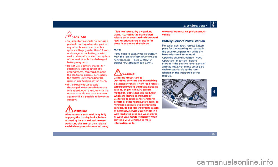
Battery Remote Posts Position For easier operation, remote battery
posts for jumpstarting are located in
the engine compartment while the
battery is stored in the trunk.
Open the engine hood (see “Hood
Operation” in section “Before
Starting”) the positive remote post (+)
and the negative remote post (-) are
easily recognizable by the icons
labeled on the integrated power
module.In an Emergency
6
313
Page 318 of 384
Jump-Start Procedure WARNING!
• Stay clear of the radiator cooling fan
whenever the engine hood is raised.
It can start anytime the ignition
switch is on. You could be injured by
the moving fan blades.
• Remove any metal jewelry such as
watch bands or bracelets that might
make an inadvertent electrical
contact. You could be seriously
injured.
• Do not allow the vehicles involved in
the jumpstarting operation to touch
each other as this could establish a
ground connection and cause
personal injury.
• Turn off the heater, radio, and all
unnecessary
electrical accessories.
•
Set the parking brake, shift the
automatic transmission into P (Park)
and turn the ignition to OFF .
• If using another vehicle to jumpstart
the battery, park the vehicle within
the jumper cables reach and set the
parking brake and make sure the
ignition is off. • Connect one terminal clamp of the
positive jumper cable to the positive
(+) remote post of the vehicle with
the discharged battery after lifting
the protection cap of the cable
indicated on the external side of the
integrated power module.
• Connect the other terminal clamp of
the positive (+) jumper cable to the
positive (+) post of the booster
battery.
• Connect one terminal clamp of the
negative jumper cable to the
negative (-) post of the booster
battery.
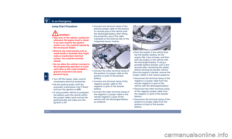
• Connect the other terminal clamp of
the negative (-) jumper cable to the
remote negative (-) post of the
vehicle with the discharged battery
as rendered. • Start the engine in the vehicle that
has the booster battery, let the
engine idle a few minutes, and then
start the engine in the vehicle with
the discharged battery. If using a
portable battery booster, wait a few
seconds after connecting the cables,
before starting the booster vehicle.
Once the engine is started, remove the
jumper cables in the reverse sequence.
• Disconnect the terminal clamp of the
negative (-) jumper cable from the
remote negative (-) post of the
vehicle with the discharged battery.
• Disconnect the other terminal clamp
of the negative jumper cable from
the negative (-) post of the booster
battery.
• Disconnect the terminal clamp of the
positive (+) jumper cable from the
positive (+) post of the booster
battery.In an Emergency
6
314