seat adjustment MASERATI LEVANTE 2019 Owners Manual
[x] Cancel search | Manufacturer: MASERATI, Model Year: 2019, Model line: LEVANTE, Model: MASERATI LEVANTE 2019Pages: 436, PDF Size: 15.24 MB
Page 65 of 436
Three-Point Seat Belt Height
Adjustment
WARNING!
• Wearing your seat belt incorrectly
could make your injuries in a
collision much worse. You might
suffer internal injuries, or you could
even slide out of the seat belt.
Follow these instructions to wear
your seat belt safely and to keep
your passengers safe, too.
• Position the shoulder belt across the
shoulder and chest with minimal, if
any slack so that it is comfortable
and not resting on your neck. The
retractor will withdraw any slack in
the shoulder belt.
• Misadjustment of the seat belt could
reduce the effectiveness of the
safety belt in a crash.
• Always make all seat belt height
adjustments when the vehicle is
stationary.
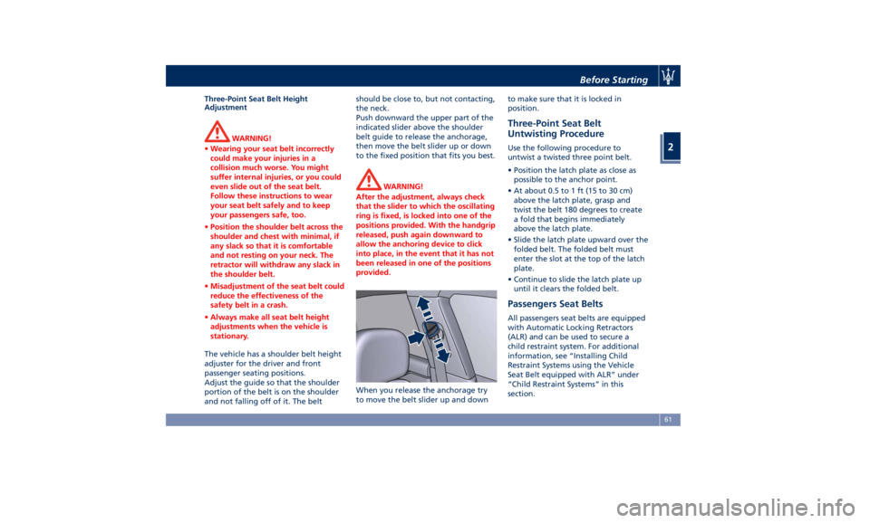
The vehicle has a shoulder belt height
adjuster
for the driver and front
passenger seating positions.
Adjust the guide so that the shoulder
portion of the belt is on the shoulder
and not falling off of it. The belt should be close to, but not contacting,
the neck.
Push downward the upper part of the
indicated slider above the shoulder
belt guide to release the anchorage,
then move the belt slider up or down
to the fixed position that fits you best.
WARNING!
After the adjustment, always check
that the slider to which the oscillating
ring is fixed, is locked into one of the
positions provided. With the handgrip
released, push again downward to
allow the anchoring device to click
into place, in the event that it has not
been released in one of the positions
provided.
When you release the anchorage try
to
move the belt
slider up and down to make sure that it is locked in
position.
Three-Point Seat Belt
Untwisting Procedure Use the following procedure to
untwist a twisted three point belt.
• Position the latch plate as close as
possible to the anchor point.
• At about 0.5 to 1 ft (15 to 30 cm)
above the latch plate, grasp and
twist the belt 180 degrees to create
a fold that begins immediately
above the latch plate.
• Slide the latch plate upward over the
folded belt. The folded belt must
enter the slot at the top of the latch
plate.
• Continue to slide the latch plate up
until it clears the folded belt.
Passengers Seat Belts All passengers seat belts are equipped
with Automatic Locking Retractors
(ALR) and can be used to secure a
child restraint system. For additional
information, see “Installing Child
Restraint Systems using the Vehicle
Seat Belt equipped with ALR” under
“Child Restraint Systems” in this
section.Before Starting
2
61
Page 97 of 436
3 – Understanding the Vehicle Interior Components ..................................... 94
Front Power Seats ....................................... 97
Driver Memory Seat ..................................... 101
Rear Seats ............................................ 103
Head Restraints ........................................ 105
Steering Wheel Adjustment ............................... 108
Adjustable Pedals (if equipped) ............................ 110
Rearview Mirrors ....................................... 110
Lights ................................................ 113
Wipers and Washers .................................... 129
Interior Features ....................................... 133
Cargo Area ........................................... 139
Front to Back Roof Rails (optional) .......................... 147
Power Sunroof with Sunshade (optional) ..................... 148
HomeLink (optional) .................................... 150
Air Conditioning Distribution ............................. 154
93
Page 101 of 436
13 Door lock button with “Passive
Entry” function.
14 Door outboard opening lock.
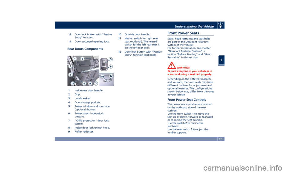
Rear Doors Components
1 Inside rear door handle.
2 Grip.
3 Loudspeaker.
4 Door storage pockets.
5 Power window and sunshade
(optional) button.
6 Power doors lock/unlock
buttons.
7 “Child protection” door lock
system.
8 Inside door lock/unlock knob.
9 Reflex reflector. 10 Outside door handle.
11 Heated switch for right rear
seat (optional). The heated
switch for the left rear seat is
on the left rear door.
12 Door lock button with “Passive
Entry” function (optional).
Front Power Seats Seats, head restraints and seat belts
are part of the Occupant Restraint
System of the vehicle.
For further information, see chapter
“Occupant Restraint System” in
section “Before Starting” and “Head
Restraints” in this section.
WARNING!
Be sure everyone in your vehicle is in
a seat and using a seat belt properly.
Depending on the different markets
and versions, the front
seats may have
different controls for adjustment and
optional features. The configurations
shown below may differ from the ones
in your vehicle.
Front Power Seat Controls The power seats switches are located
on the outboard side of the seat
cushion.
Use the front switch 1 to move the
seat up or down, forward or rearward
or to recline the seat cushion.
Use the switch 2 to recline the
seatback.
Use the rear switch 3 to adjust the
lumbar support.Understanding the Vehicle
3
97
Page 102 of 436
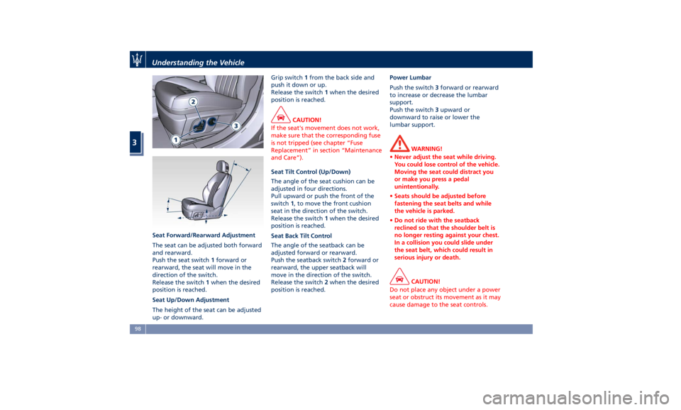
Seat Forward/Rearward Adjustment
The seat can be adjusted both forward
and rearward.
Push the seat switch 1 forward or
rearward, the seat will move in the
direction of the switch.
Release the switch 1 when the desired
position is reached.
Seat Up/Down Adjustment
The height of the seat can be adjusted
up- or downward. Grip switch 1 from the back side and
push it down or up.
Release the switch 1 when the desired
position is reached.
CAUTION!
If the seat's movement does not work,
make sure that the corresponding fuse
is not tripped (see chapter “Fuse
Replacement” in section “Maintenance
and Care”).
Seat Tilt Control (Up/Down)
The
angle of the seat cushion can be
adjusted in four directions.
Pull upward or push the front of the
switch 1 , to move the front cushion
seat in the direction of the switch.
Release the switch 1 when the desired
position is reached.
Seat Back Tilt Control
The angle of the seatback can be
adjusted forward or rearward.
Push the seatback switch 2 forward or
rearward, the upper seatback will
move in the direction of the switch.
Release the switch 2 when the desired
position is reached. Power Lumbar
Push the switch 3 forward or rearward
to increase or decrease the lumbar
support.
Push the switch 3 upward or
downward to raise or lower the
lumbar support.
WARNING!
• Never adjust the seat while driving.
You could lose control of the vehicle.
Moving the seat could distract you
or make you press a pedal
unintentionally.
• Seats should be adjusted before
fastening the seat belts and while
the vehicle is parked.
• Do not ride with the seatback
reclined so that the shoulder belt is
no longer resting against your chest.
In a collision you could slide under
the seat belt, which could result in
serious injury or death.
CAUTION!
Do not place any object under a power
seat or obstruct its movement as it may
cause damage to the seat controls.Understanding the Vehicle
3
98
Page 110 of 436
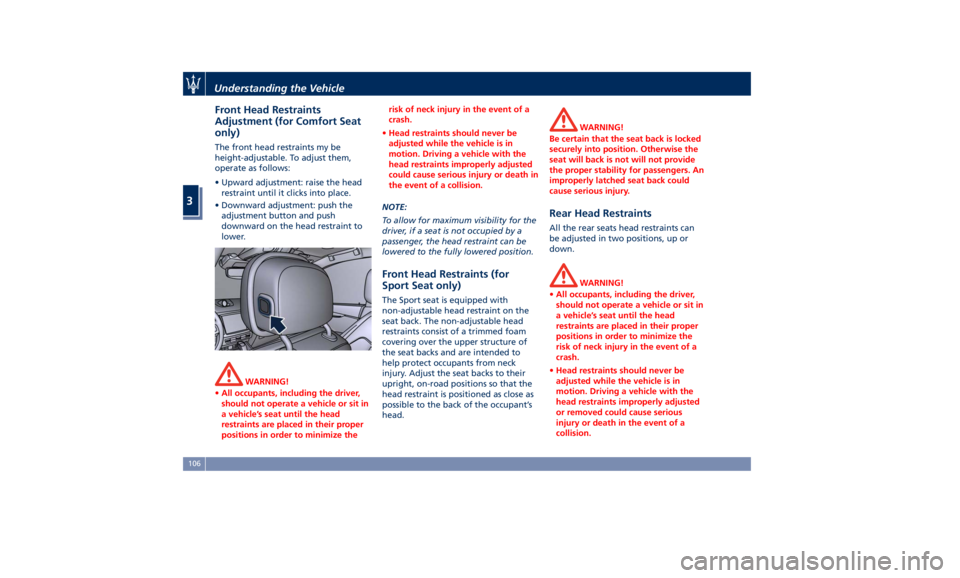
Front Head Restraints
Adjustment (for Comfort Seat
only) The front head restraints my be
height-adjustable. To adjust them,
operate as follows:
• Upward adjustment: raise the head
restraint until it clicks into place.
• Downward adjustment: push the
adjustment button and push
downward on the head restraint to
lower.
WARNING!
• All occupants, including the driver,
should not operate a vehicle or sit in
a vehicle’s seat until the head
restraints are placed in their proper
positions in order to minimize the risk of neck injury in the event of a
crash.
• Head restraints should never be
adjusted while the vehicle is in
motion. Driving a vehicle with the
head restraints improperly adjusted
could cause serious injury or death in
the event of a collision.
NOTE:
T
o allow for maximum visibility for the
driver, if a seat is not occupied by a
passenger, the head restraint can be
lowered to the fully lowered position.
Front Head Restraints (for
Sport Seat only) The Sport seat is equipped with
non-adjustable head restraint on the
seat back. The non-adjustable head
restraints consist of a trimmed foam
covering over the upper structure of
the seat backs and are intended to
help protect occupants from neck
injury. Adjust the seat backs to their
upright, on-road positions so that the
head restraint is positioned as close as
possible to the back of the occupant’s
head. WARNING!
Be certain that the seat back is locked
securely into position. Otherwise the
seat will back is not will not provide
the proper stability for passengers. An
improperly latched seat back could
cause serious injury.
Rear Head Restraints All the rear seats head restraints can
be adjusted in two positions, up or
down.
WARNING!
• All occupants, including the driver,
should not operate a vehicle or sit in
a vehicle’s seat until the head
restraints are placed in their proper
positions in order to minimize the
risk of neck injury in the event of a
crash.
• Head restraints should never be
adjusted while the vehicle is in
motion. Driving a vehicle with the
head restraints improperly adjusted
or removed could cause serious
injury or death in the event of a
collision.Understanding the Vehicle
3
106
Page 111 of 436
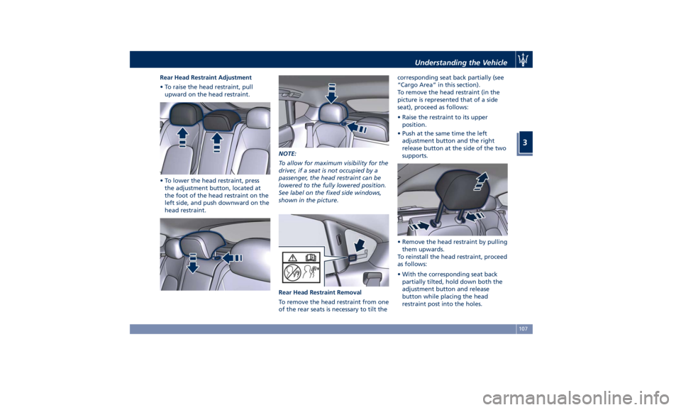
Rear Head Restraint Adjustment
• To raise the head restraint, pull
upward on the head restraint.
• To lower the head restraint, press
the adjustment button, located at
the foot of the head restraint on the
left side, and push downward on the
head restraint. NOTE:
To allow for maximum visibility for the
driver, if a seat is not occupied by a
passenger, the head restraint can be
lowered to the fully lowered position.
See label on the fixed side windows,
shown in the picture.
Rear Head Restraint Removal
To remove the head restraint from one
of the rear seats is necessary to tilt the corresponding seat back partially (see
“Cargo Area” in this section).
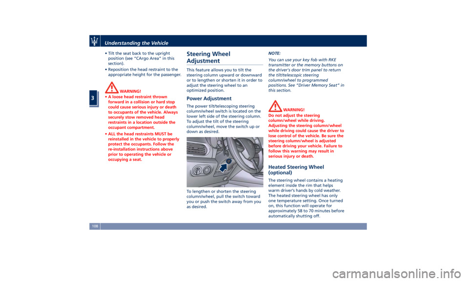
To remove the head restraint (in the
picture is represented that of a side
seat), proceed as follows:
• Raise the restraint to its upper
position.
• Push at the same time the left
adjustment button and the right
release button at the side of the two
supports.
• Remove the head restraint by pulling
them upwards.
To reinstall the head restraint, proceed
as follows:
• With the corresponding seat back
partially tilted, hold down both the
adjustment button and release
button while placing the head
restraint post into the holes.Understanding the Vehicle
3
107
Page 112 of 436
• Tilt the seat back to the upright
position (see “CArgo Area” in this
section).
• Reposition the head restraint to the
appropriate height for the passenger.
WARNING!
• A loose head restraint thrown
forward in a collision or hard stop
could cause serious injury or death
to occupants of the vehicle. Always
securely stow removed head
restraints in a location outside the
occupant compartment.
• ALL the head restraints MUST be
reinstalled in the vehicle to properly
protect the occupants. Follow the
re-installation instructions above
prior to operating the vehicle or
occupying a seat. Steering Wheel
Adjustment This feature allows you to tilt the
steering column upward or downward
or to lengthen or shorten it in order to
adjust the steering wheel to an
optimized position.
Power Adjustment The power tilt/telescoping steering
column/wheel switch is located on the
lower left side of the steering column.
To adjust the tilt of the steering
column/wheel, move the switch up or
down as desired.
To lengthen or shorten the steering
column/wheel, pull the switch toward
you or push the switch away from you
as desired. NOTE:
You can use your key fob with RKE
transmitter or the memory buttons on
the driver's door trim panel to return
the tilt/telescopic steering
column/wheel to programmed
positions. See “Driver Memory Seat” in
this section.
WARNING!
Do not adjust the steering
column/wheel while driving.
Adjusting the steering column/wheel
while driving could cause the driver to
lose control of the vehicle. Be sure the
steering column/wheel is adjusted
before driving your vehicle. Failure to
follow this warning may result in
serious injury or death.
Heated Steering Wheel
(optional) The steering wheel contains a heating
element inside the rim that helps
warm driver’s hands by cold weather.
The heated steering wheel has only
one temperature setting. Once turned
on, this function will operate for
approximately 58 to 70 minutes before
automatically shutting off.Understanding the Vehicle
3
108
Page 218 of 436
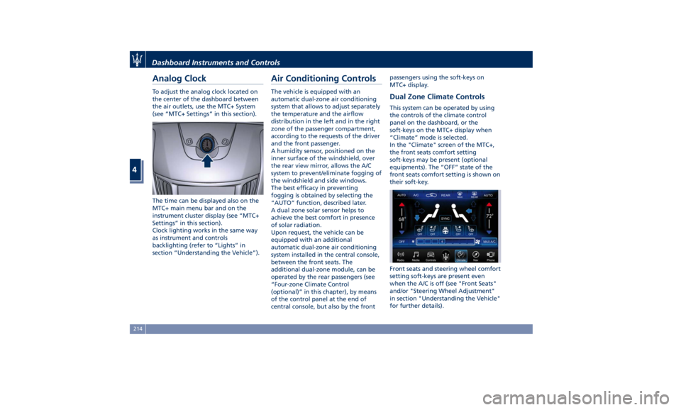
Analog Clock To adjust the analog clock located on
the center of the dashboard between
the air outlets, use the MTC+ System
(see “MTC+ Settings” in this section).
The time can be displayed also on the
MTC+ main menu bar and on the
instrument cluster display (see “MTC+
Settings” in this section).
Clock lighting works in the same way
as instrument and controls
backlighting (refer to “Lights” in
section “Understanding the Vehicle”). Air Conditioning Controls The vehicle is equipped with an
automatic dual-zone air conditioning
system that allows to adjust separately
the temperature and the airflow
distribution in the left and in the right
zone of the passenger compartment,
according to the requests of the driver
and the front passenger.
A humidity sensor, positioned on the
inner surface of the windshield, over
the rear view mirror, allows the A/C
system to prevent/eliminate fogging of
the windshield and side windows.
The best efficacy in preventing
fogging is obtained by selecting the
“AUTO” function, described later.
A dual zone solar sensor helps to
achieve the best comfort in presence
of solar radiation.
Upon request, the vehicle can be
equipped with an additional
automatic dual-zone air conditioning
system installed in the central console,
between the front seats. The
additional dual-zone module, can be
operated by the rear passengers (see
“Four-zone Climate Control
(optional)” in this chapter), by means
of the control panel at the end of
central console, but also by the front passengers using the soft-keys on
MTC+ display.
Dual Zone Climate Controls This system can be operated by using
the controls of the climate control
panel on the dashboard, or the
soft-keys on the MTC+ display when
“Climate” mode is selected.
In the "Climate" screen of the MTC+,
the front seats comfort setting
soft-keys may be present (optional
equipments). The “OFF” state of the
front seats comfort setting is shown on
their soft-key.
Front seats and steering wheel comfort
setting soft-keys are present even
when the A/C is off (see "Front Seats"
and/or "Steering Wheel Adjustment"
in section "Understanding the Vehicle"
for further details).Dashboard Instruments and Controls
4
214
Page 371 of 436
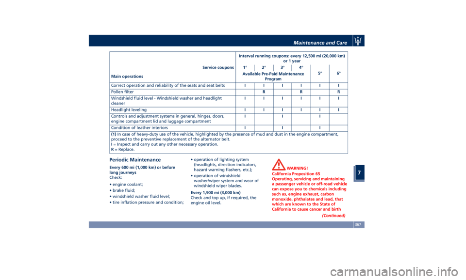
Interval running coupons: every 12,500 mi (20,000 km)
or 1 year
Service coupons 1° 2° 3° 4°
5° 6°
Main operations Available Pre-Paid Maintenance
Program
Correct operation and reliability of the seats and seat belts IIIIII
Pollen filter RRR
Windshield fluid level - Windshield washer and headlight
cleaner IIIIII
Headlight leveling IIIIII
Controls and adjustment systems in general, hinges, doors,
engine compartment lid and luggage compartment III
Condition of leather interiors III
(1) In case of heavy-duty use of the vehicle, highlighted by the presence of mud and dust in the engine compartment,
proceed to the preventive replacement of the alternator belt.
I = Inspect and carry out any other necessary operation.
R = Replace.
Periodic Maintenance Every 600 mi (1,000 km) or before
long journeys
Check:
• engine coolant;
• brake fluid;
• windshield washer fluid level;
• tire inflation pressure and condition; • operation of lighting system
(headlights, direction indicators,
hazard warning flashers, etc.);
• operation of windshield
washer/wiper system and wear of
windshield wiper blades.
Every 1,900 mi (3,000 km)
Check and top up, if required, the
engine oil level. WARNING!
California Proposition 65
Operating, servicing and maintaining
a passenger vehicle or off-road vehicle
can expose you to chemicals including
such as, engine exhaust, carbon
monoxide, phthalates and lead, that
which are known to the State of
California to cause cancer and birth
(Continued)Maintenance and Care
7
367
Page 432 of 436
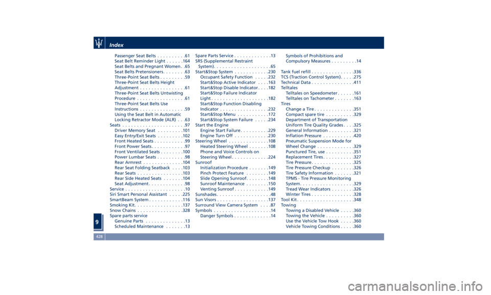
Passenger Seat Belts ..........61
Seat Belt Reminder Light ..... .164
Seat Belts and Pregnant Women . .65
Seat Belts Pretensioners ........63
Three-Point Seat Belts .........59
Three-Point Seat Belts Height
Adjustment ................61
Three-Point Seat Belts Untwisting
Procedure .................61
Three-Point Seat Belts Use
Instructions ................59
Using the Seat Belt in Automatic
Locking Retractor Mode (ALR) . . .63
Seats ......................97
Driver Memory Seat ........ .101
Easy Entry/Exit Seats ........ .102
Front Heated Seats ...........99
Front Power Seats ............97
Front Ventilated Seats ....... .100
Power Lumbar Seats ..........98
Rear Armrest ............. .104
Rear Seat Folding Seatback . . . .103
Rear Seats ............... .103
Rear Side Heated Seats ...... .104
Seat Adjustment .............98
Service .....................10
Siri Smart Personal Assistant .... .225
SmartBeam System ........... .116
Smoking Kit ................ .137
Snow Chains ............... .328
Spare parts service
Genuine Parts ..............13
Scheduled Maintenance .......13 Spare Parts Service .............13
SRS (Supplemental Restraint
System) ....................65
Start&Stop System ........... .230
Occupant Safety Function .... .232
Start&Stop Active Indicator . . . .163
Start&Stop Disable Indicator . . . .182
Start&Stop Failure Indicator
Light ................... .182
Start&Stop Function Disabling
Indicator ................ .232
Start&Stop Menu .......... .172
Start&Stop System Failure .... .234
Start the Engine
Engine Start Failure ......... .229
Engine Turn Off ........... .230
Steering Wheel .............
.108
Heated
Steering Wheel ...... .108
Phone
and Voice Controls on
Steering Wheel ............ .224
Sunroof
Initialization Procedure ...... .149
Pinch Protect Feature ....... .149
Slide Opening Sunroof ....... .148
Sunroof Maintenance ....... .150
Venting Sunroof ........... .149
Sunshades ...................48
Sun Visors ................. .137
Surround View Camera System ....87
Symbols ....................14
Danger Symbols .............14 Symbols of Prohibitions and
Compulsory Measures .........14
Tank fuel refill .............. .336
TCS (Traction Control System) .... .275
Technical Data .............. .411
Telltales
Telltales on Speedometer ..... .161
Telltales on Tachometer ...... .163
Tires
Change a Tire ............. .351
Compact spare tire ......... .329
Department of Transportation
Uniform Tire Quality Grades . . . .325
General Information ........ .321
Inflation Pressure .......... .420
Pneumatic Suspension Mode for
Wheel Change ............ .329
Punctured Tire, use ......... .351
Replacement Tires .......... .327
Tire Pressure .............. .325
Tire Pressure Checkup ....... .326
Tire Safety Information ...... .321
TPMS - Tire Pressure Monitoring
System .................. .329
Tread Wear Indicators ....... .326
Winter Tires .............. .328
ToolKit................... .348
Towing
Towing a Disabled Vehicle .... .360
Towing the Vehicle ......... .360
Use
the Vehicle Tow Hook .... .360
Vehicle Towing Conditions .... .360Index
9 428