G INDEX
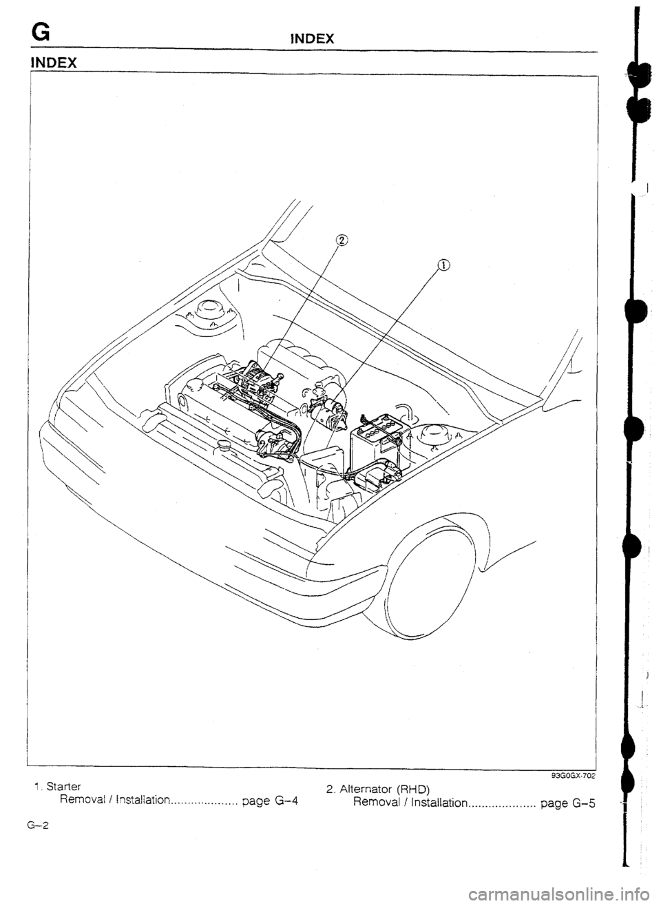
1. Starter 93GOGX-702
Removal I Instaltation... ._. . . . . . . , . . ._._, page G-4 2. Alternator (RFD)
Removal I Installation. . . .._.. . . . . . . . . . . . .
page G-5
G-2
OUTLINE G
L
i i-
OUTLINE
OUTLINE OF CONSTRUCTION
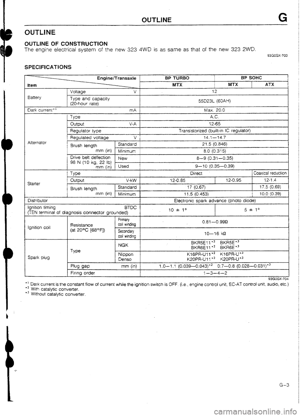
The engine electrical system of the new 323 4WD is as same as that of the new 323 ZWD.
93GOGX-703
SPECIFICATIONS
Item
Battery t
Voltaae EnginelTransaxle
v
Type and capacity
120-hour rate) BP TURBO
MTX BP SOHC
MTX ATX 12
55D23L (60AH)
I
Dark current” mA 1 Max. 20.0
Alternator
Output V-A 12-65
Regulator type Transistorized (built-in iC regulator)
1 I Regulated voltage v
74.1---14.7
Brush length Standard 21.5 (0.846)
mm (in)
Minrmum 8.0 (0.315)
Drive belt deflection
New
98 N (10 kg, 22 lb) 8-9 (0.31-0.35)
mm (in) Used 9-l 0 (0.35-0.39)
Type Direct ] Coaxicat reductron Starter Output V-W
12-U-85 12-0.95 32-l .4
8rush length Standard 17 (0.67) 17.5 (0.69)
mm [in) Minimum 11.5 (0.4531 10.0 (0.39) Distributor
Ignition timing
BTDC
FEN termrnal of diagnosis connector grounded) Electronic spark advance (photo
diode)
10 * I0 5 f lo
Ignition coil Resistance
(at 20°C [68OFj)
I
Primary
coil windinq
I
Spark plug Type I
Secondary 1
f coil windina 1
NGK
Nippon
Denso 10-76 kS-l
8KR5Ell +2 BKR5E”3
BKRGEI 1 l * BKRGE *3
KIGPR-Ull *2 KfGPR-I-Y3
K20PR-Ul l ** K20PR-U
l 3 0.81 ---o-999
pw am
Firrng order
I mm (in) 1.0-I .l (0.039-0.043)“2 0.7-0.8 (0.028-0.03i)*3
l-3-4-2
93GOGX-704
*I Dark current is the constant flow of current while the ignition switch is OFF. (i.e., engine control unit, EC-AT control unit, audro, etc.)
+’ With catalytic converter.
*3 Without catalytic converter.
G-3
CHARGWIG SYSTEM G
CHARGING SYSTEM
PREPARATION
SST
49 0118 85OC For
Puller, ball joint removal of ball
joint
93GOGX-707
ALTERNATOR (RHD)
Removal / Installation
I. Remove in the order shown in the figure.
2. Install in the reverse order of removal, referring to Installation Note.
1
37-52 (3.8-5.3, 27 37-52 (3.8-5.3, 27
72.0, 65-81)
37-52 (3.8-5.3, 27-38) 37-52 (3.8-5.3, 27-38)
N-m (m-kg, ft-lb) N-m (m-kg, ft-lb)
93G?GX-70 93G?GX-70
I. Negative battery cable I. Negative battery cable 7. Stabilizer (Right) 7. Stabilizer (Right)
2. Tire and wheel (Right front) 2. Tire and wheel (Right front) Installation Installation Note . . . . . . . . . . . . . -. . I -. . . . - . . . . page G-6 Note . . . . . . . . . . . . . -. . I -. . . . - . . . . page G-6
3. Undercover 3. Undercover 8. Lower arm (Right) 8. Lower arm (Right)
4. Crossmember 4. Crossmember 9. Driveshaft (Right) 9. Driveshaft (Right)
5. Front exhaust pipe 5. Front exhaust pipe IO. Alternator connectors IO. Alternator connectors
6. Tie-rod end 6. Tie-rod end 11. Alternator 11. Alternator
Removal Note ._....._.........._..._ ._..... page G-6 Removal Note ._....._.........._..._ ._..... page G-6 Remove from below Remove from below
G-5 G-5


