torque MAZDA 232 1990 Suplement Owner's Manual
[x] Cancel search | Manufacturer: MAZDA, Model Year: 1990, Model line: 232, Model: MAZDA 232 1990Pages: 677, PDF Size: 61.19 MB
Page 78 of 677

INSTAlLATION B2
93X82-72!
93G0BZ757
-
J 93GO32-730
Alternator and drive belt
1. Monut the alternator to the engine.
Tightening torque
@: 19-25 N-m (1.9-2.6
m-kg, 14-19 ft-lb)
@J: 37-52 N-m (3.8-5.3 m-kg, 27-38 ft-lb)
2. Install the drive belt. (Refer to page 82-Z)
Engine mount, clutch release cylinder
and engine mount
member
1. Install the No.3 engine mount rubber, and loosely tighten
the bott and nuts.
2. Install the No.4 engine mount rubber and bracket assem-
bly, and loosely tighten the bolts and nuts.
3. lnstalt the clutch release cylinder and pipe bracket assembly.
Tightening torque
@: 16-23 Nm [I .6-2.3 m-kg, 12-17 ft-lb)
0: 6.9-9.8 N-m (70-100 cm-kg, 61-87 in-lb)
4. Install the No.2 engine mount rubber and bracket assembly.
Tightening torque:
37-52 Nrn (3.8-5.3 m-kg, 27-38 R-lb)
B2-25
Page 79 of 677

INSTALLATION
5. Align the engine mount member to the No.1 and No.2 en-
gine mount boIts, and loosely tighten the nuts.
6. k-&all and tighten the engine mount member bolt and nuts.
Tightening torque:
64-89 N-m (6-509.1 m-kg, 47-66 Mb)
7. Tighten the No.1 and No.2 engine mount nuts.
Tightening torque:
37-52 N-m (3.8-5.3 m-kg, 27-38 ft-lb)
8. Tighten bolts @ in two or three steps in the order shown.
Tightening torque:
43-61 Nom (4.4-6.2 m-kg, 32-43 ft-lb)
9. Tighten nuts @.
Tightening torque:
67-93 N-m (6.8-9.5 m-kg, 49-69 f%(b)
03UOBX-828 IO. Tighten the No.3 engine mount nuts @.
93G052-731
93GOB2-73;
Tightening torque:
74-103 N-m (7.5-10.5 m-kg, 54-76 ft-Ib)
11. Tighten No.3 engine mount nut @.
Tightening torque:
67-93
N-m (6.8-9.5 m-kg, 49-69 ftdb)
12. Install the dynarpic damper.
Tightening torque:
55-80 Nom (5.6-8-2 m-kg, 41-59 ft-lb)
13. Remove the chain hoist.
Intercooler bracket
1, Install the intercooler bracket.
Tightening torque:
19-25 him (1.9-2.6 m-kg, 14-I 9 ft-lb)
Page 80 of 677

INSTALLATION
step 3
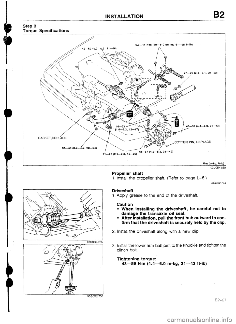
Torque Specifications
6.9-11 Nn-i (70-110 cm-kg, 6l--95 in-lb)
0 (2.8-3.1, 20-221
59 (4.4-6.0, 3143)
GASKET,REPtiCE
/
/
31-46 (3.24.7, 23-34) ~//<~~z”““‘” PIN REP!JCE
21-2? (2.3-2.8, 15-20) - - - - ’
N-m (m-kg, fi-tb)
93GOB2.736
Propeller shaft
I. Install the propeller shaft. (Refer to page L-5.)
93GOB2-734
Drive&aft
I. Apply grease to the end of the driveshaft.
Caution
l When installing the driveshaft, be careful not to
damage the transaxle oil seal.
l After installation, pull the front hub outward to con-
firm that the driveshaft is securefy held by the clip.
2. Install the driveshaft along with a new clip.
3. tnstall the lower arm ball joint to the knuckle and tighten the
clinch bolt.
Tightening torque:
43-59 Nm (4.4-6.0 m-kg, 31-43 ft-lb)
82-27
Page 81 of 677

INSTALLATION
I
1 93EOB2-061
03 UOBX-848
93EOBZ07E
93GOB2-760
93GOB2-737
E32-28
4. Install the joint shaft.
5. Tighten the bolts in the order shown.
Tightening torque: 42-62
N=m (4.3-6.3 m-kg, 31-46 ft-lb)
Tie-rod end
1. Install the tie-rod end to the
knuckle.
Tightening torque: 42-57
Nmm (4.3-5.8 m-kg, 31-42 ft-lb)
Z.-Install a new cotter pin.
StabiIiter
I. Install and adjust the stabilizer.
Dimension A: 17.19mm (0.67-0.75 in)
Tightening torque:
f 6-23 Nm (I .6-2.3 m-kg, 12-17 ft-lb)
Exhaust pipe
I. InstaIl the exhaust pipe along with
a new gasket,
tighten locknuts @:
Loose1 y tighten brat ket
Tighten locknuts @
nuts @
and loosely
2.
3.
Tightening torque:
31-46 Mm (3.2-4.7 m-kg, 23-34 ft.lb) 4.
Tighten bracket nuts @,
Tightening torque: 21-27
Nm (2.1-2.8 m-kg, 15-20 ft-lb)
Select and
shift cables
1. Install the select cable and the spring pin.
2. Install the shift cable and the spring pin,
Page 83 of 677

B2 INSTALLATION
Step 5
1. Connect the harness connectors shown in the figure.
ALTERNATOR OIL PF;IESSURE SWITCH PRESSURE REGULATOR
STARTER CONTROL VAVLE
GRoYD O-i-l-tE SENSOR
IDLE-SPEED CONTROL
KNOCK SENSOR
OXYGEhENSO$
Step 6
Torque Specifications
03UO8X-33’
7.8-11 N-m
(80-110 cm-kg, 69- .
11 N-m (80--f ’IO cm-kg, 69-95 in-lb)
N-m
cm-kg, 69-95 in-Ib)
37-52 (3.8-5.3, 27
7.8--fl N-m (80 107 (9.6-T 1.9, 69-79)
N-m (m-kg, ft-lb)
03U03X-83
Page 84 of 677

lNSTAL&ATlON B2
03UOSX-839
93G032-76:
9313082-738
/
\ I
Crossmember
1. Install the crossmember.
Tightening torque:
93-107 Nm (9.5-l I .9 m-kg, 69-79 f&lb)
A/c compressor
1. Install the A/C compressor.
Tightening torque:
24-35 Nom (2.4-3.6 m-kg, 17-26 ft-lb)
P/S oil pump and bracket
I. Install the P/S oil pump and bracket.
Tightening torque:
37-52 Nm (3.8-5.3 m-kg, 27-38 ft-lb)
Drive belt
I. Install the P/S and/or A/C drive belt.
2. Adjust the drive belt deflections. (Refer to page 82-2)
Air pipe
1. Install a new gasket and install the air pipe.
Tightening torque:
19-25 N-m (1.9-2.6 m-kg, 14-19 Mb)
Intercooler and air pipe assembty
t . Lift the intercooler and air pipe assembly from the bottom
of the vehicle, and install hose @ in pipe @ .
2. Install and tighten the mounting bolt and nut.
Tightening torque:
7.8-l 1 Nom (80-l 10 cm-kg, 69-95 in-lb)
3. Tighten hose clamp 0.
B2-31
Page 85 of 677

B2 INSTALLATION
93GOB2-74 1
93GOB2-743
82-32
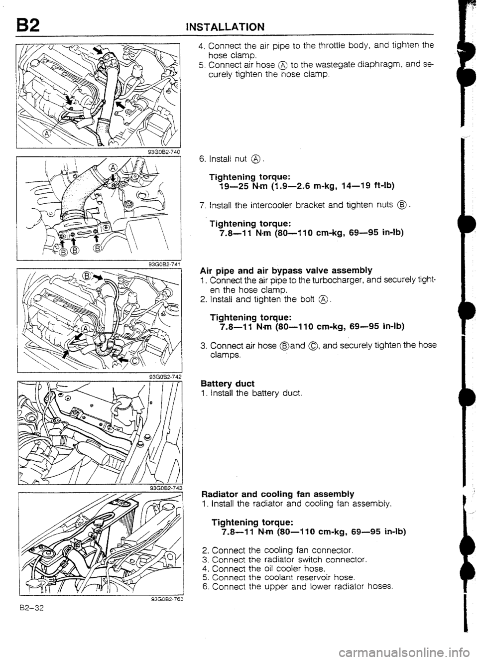
4. Connect the air pipe to the throttle body, and tighten the
hose clamp.
5. Connect air hose @ to the wastegate diaphragm,
and se-
curely tighten the hose clamp.
6. Install nut @
Tightening torque:
19-25 Narn (1.9-2.6 m-kg, 14-19 ft-lb)
7. Install the intercooter bracket and tighten nuts @J .
Tightening torque:
7.8-l 1 Narn (80-I IO cm-kg, 69-95 in-lb)
Air pipe and air bypass valve assembly
1. Connect the air pipe to the turbocharger, and securely tight-
en the hose clamp.
2. Install and tighten the bolt @ .
Tightening torque:
7.8-l 1 Nom (80-I 10 cm-kg, 69-95 in-ib)
3. Connect air hose @and Q1 and securely tighten the hose
clamps.
Battery duct
1. install the battery duct.
Radiator and tooting fan assembly
1. Install the radiator and cooling fan assembly.
Tightening torque:
7.8-l 1 Nm (80-l 10 cm-kg, 69-95 Mb)
2. Connect the tooting fan connector.
3. Connect the radiator switch connector.
4. Connect the oil cooler hose.
5. Connect the coolant reservoir hose.
6. Connect the upper and lower radiator hoses.
Page 86 of 677

INSTALLATION
93G082-7ti
HERE
/+Ju 7
93GOB2-74!
Caution
l Position the hose clamp in the original location on
the hose, and squeeze it lightly with large pliers to
ensure a good fit.
Accelerator cable
1. Install the accelerator
cable.
Tightening torque
@): 7.8-l 1 N4m (80-l 10 cm-kg, 69-95 in-lb)
2. Adjust the cable deflection by turning nuts @ .
Deflection: I-3mm (U&4--0.12 in)
Battery carrier and battery
1 . Install the battery carrier.
Tightening torque:
7.8-l 1 N4m (80-I IO cm-kg, 69-95 in-lb)
2. Install the battery and the battery cover.
3. Install the battery bracket.
Tightening torque:
2.9-5.9 N.m (30-60 cm-kg, 26-52 in-lb)
4. Connect the positive battery cable.
Air cleaner assembly
1. Install the air cleaner assembly.
Tightening torque:
19-25 N-m (1.9-2.6 m-kg, 14-19 ft-lb)
2. Connect the airflow sensor connector.
3. Connect the hoses shown in the figure.
Strut tower bar
I. Instail the strut tower bar.
Tightening torque:
88-108 Narn (9.0-11 .U m-kg, 65-80 ft-lb)
Undercover and side cover
1. Install the undercovers and side covers.
93GOB2-746
82-33
Page 101 of 677

E RADIATOR THERMUSWlTCki
RADIATOR THERMOSWITCH (BP DUHC TURBO)
REMOVAL I INSPECTION I INSTALLATION
I. Disconnect the negative battery cable.
2. Remove in the order shown in the figure.
3. Install in the reverse order of removal, referring to InstaHation Note.
7.8-13 H-m
(80-l 10 cm-kg, 69-95 h-lb)
(80-110 cm-kg,
69-95In4b)
REPLACE 1. Resonance chamber
2. Radiator cowling mounting bolts
3. Radiator thermoswitch connector
03WEX-027 4. Radiator thermoswitch
Inspection . . . . . . . . * . . . . . . . . . . . . . ..-. -.*,.a..- . . . . . . .I. below
Installation Note _.,............................._. below
1NSPECTlON 1. Place the switch and a thermometer in engine oil.
Warning
l Do not heat the engine oil above 12O*C (248OF) 2. Heat the engine oil gradually and check continuity of the
switch with
an ohmmeter.
Engine oil temperature “C (*F) Continuity
More than 105 (221) Yes I
t Less than 96 (205) No
1
3. If not as specified, replace the radiator thermoswitch.
Installation Note
Radiator thermoswitch
Caution
l Do not use an impact wrench for installation. 1. Install the radiator thermoswitch along with a new gasket.
Tightening torque: 5.9-12
Nom (60-120 cm-kg, 52-104 in-lb) 93GOEX.721 E-12
Page 129 of 677
![MAZDA 232 1990 Suplement Owners Manual F2 TURBOCHARGER CONTROL [BP TURBO]
TURBOCHARGER CONTROL [BP TURBO]
OUTLINE
l The air-to-air intercooler is adopted to lower intake air temperature and to improve engine performance.
l With additio MAZDA 232 1990 Suplement Owners Manual F2 TURBOCHARGER CONTROL [BP TURBO]
TURBOCHARGER CONTROL [BP TURBO]
OUTLINE
l The air-to-air intercooler is adopted to lower intake air temperature and to improve engine performance.
l With additio](/img/28/57056/w960_57056-128.png)
F2 TURBOCHARGER CONTROL [BP TURBO]
TURBOCHARGER CONTROL [BP TURBO]
OUTLINE
l The air-to-air intercooler is adopted to lower intake air temperature and to improve engine performance.
l With addition of the wastegate control system, engine torque at higher rpm is increased.
AIR BYPASS VALVE
WASTEGATE
SOLENOID VALVE
TURBOCHAR
ACTUATOR
-
SYSTEM DIAGRAM
AIR BYPASS VALVE 1
t
!NTERCOOLER
n Ii Y7rzFes-~ m I
-
TUREiOCHARGER
WASTEGATE SOLENO1D VALVE
93GOF2-7 7
FZ-12