torque MAZDA 232 1990 Workshop Manual Suplement
[x] Cancel search | Manufacturer: MAZDA, Model Year: 1990, Model line: 232, Model: MAZDA 232 1990Pages: 677, PDF Size: 61.19 MB
Page 6 of 677
HOW TO USE TtiIS MANUAL GI
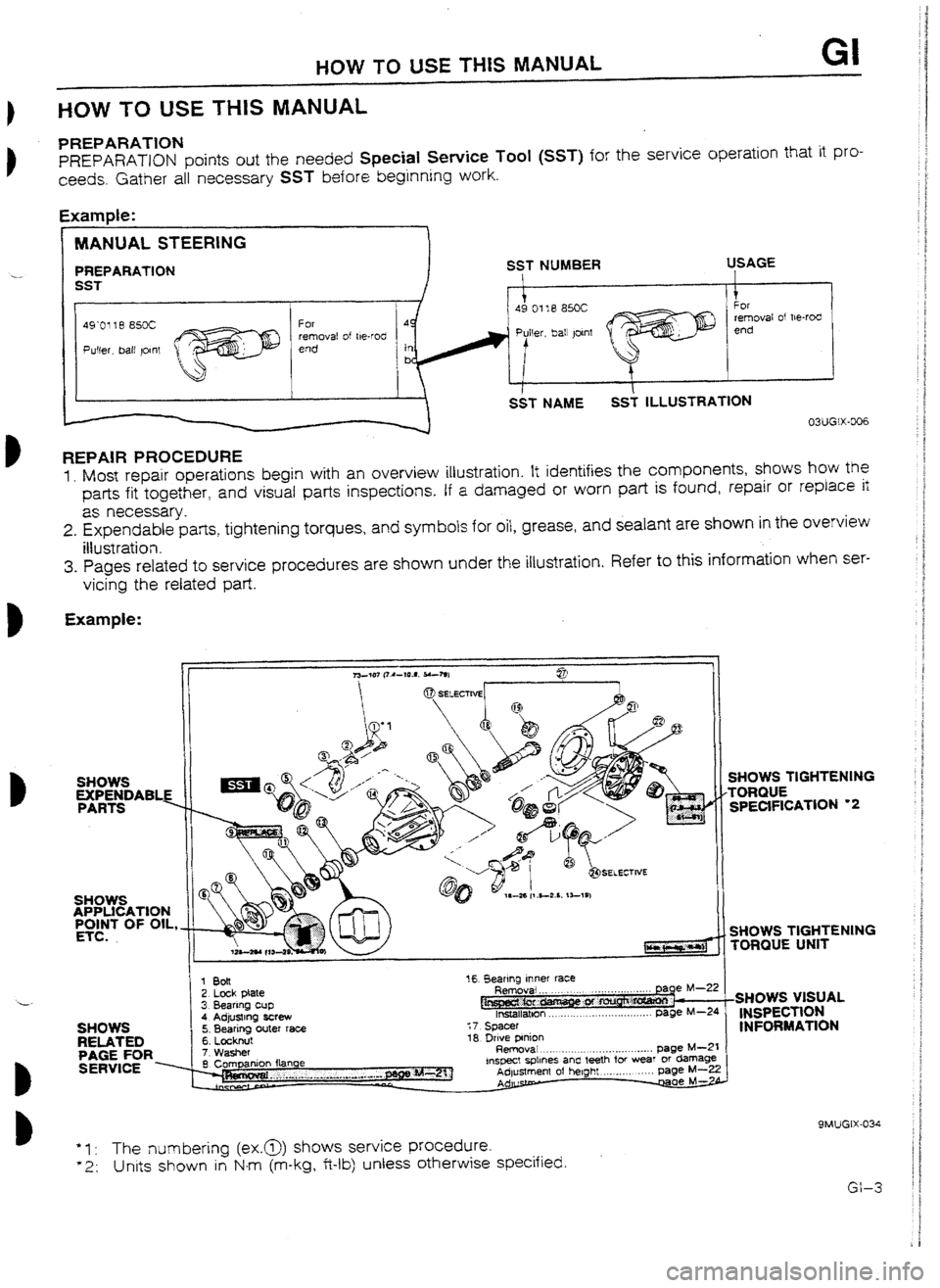
HOW TO USE THIS MANUAL
PREPARATION
PREPARATON points out the needed SpeciaI Service Tool (SST) for the service operation that it pro-
ceeds. Gather all necessary SST before beginning work.
Example:
MANUAL STEERING
PREPARATION
remova! of W-rod
REPAIR PROCEDURE I.
Most repair operations begin with an overview illustration. It identifies the components, shows how the
parts fit together, and visual parts inspections. If a
damaged or worn part is found, repair or replace it
as necessary.
2. Expendable parts, tightening torques, and symbols for oil, grease, and sealant are shown in the overview
iItustration.
3. Pages related to service procedures are shown under the illustration. Refer to this information when ser-
vicing the related part.
Example: --__ __-
EXPENDABLE iI
-
SHOWS TlGHTENlNG
TORQUE UNIT
-
SHOWS Zh REiAT&
PAGE FOR 1 8oit
16 Bearing lnne
2. Lock plate Removal . .
,.
3. Bearrng cup
I!.~ f%
fnstallatbon ._ . . . ._. . . . . .
I
A Adirtstma drew - _ ‘.v,--..s ----. 5. Bearing outer race :7 Spacer
G I h-tnllt 1R hriu* mninn
I V. LVYR*IY. .” I.~.1 7Washer Rerr&l'~ .._. . . . . ..__ . . . . . . . ..__......... page M---21
- -0mpanlon f&we inspect spllnes and teeth for wear or damage Adlustment of heloht ._._..... . . . . . DaPe k&Z?
I
r..r...~r.--~.~r....e.-..c~~...~.,~.-*
Q SERVICE x
9MUGlx-034 ‘I : The numbering (ex.@))
shows service procedure. ‘2: Units shown
in N-m (m-kg, Wb) unless otherwise specified.
Page 9 of 677
GI FUNDAMENTAL PROCEDURES
9MUGtX-040
SMLIGIX-041
SMUGIX-004
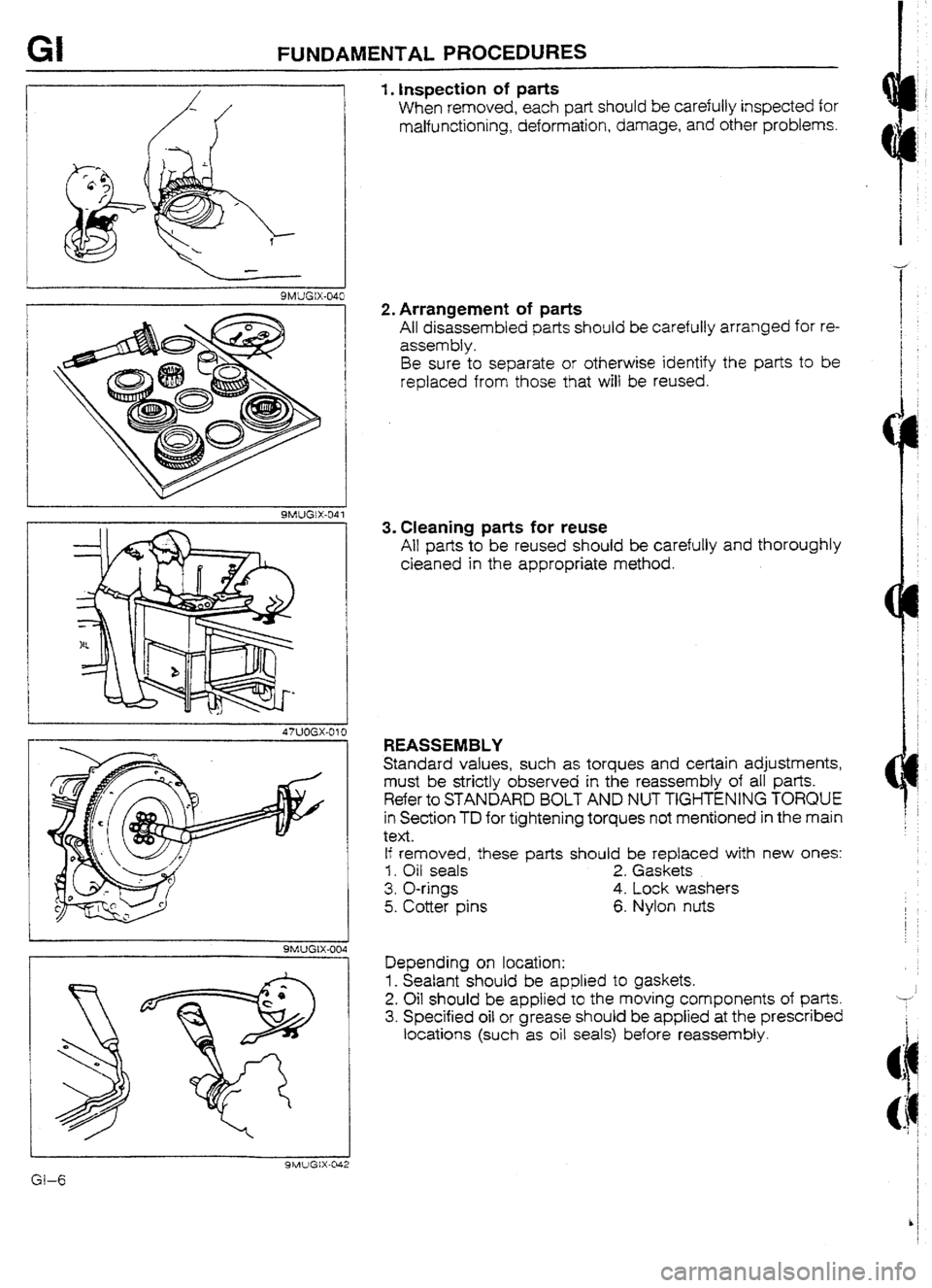
1. Inspection of parts
When removed, each part should be carefully inspected for
malfunctioning, deformation, damage, and other problems.
2. Arrangement of parts
All disassembled parts should be carefully arranged for re-
assembly.
Be sure to separate or otherwise identify the parts to be
replaced from those that will be reused.
3. Cleaning parts for reuse
All parts to be reused should be carefully and thoroughly
cleaned in the appropriate method.
REASSEMBLY
Standard values, such as torques and certain adjustments
must be strictly observed in the reassembly of all parts.
Refer to STANDARD BOLT AND NUT TIGHTENING TORQUE
in Section TD for tightening torques not mentioned in the main
text.
If removed, these parts should be replaced with new ones:
1. Oil seals 2. Gaskets
3. O-rings
4. Lock washers
5. Cotter pins 6. Nylon nuts
Depending on location:
1. Sealant should be applied to gaskets.
2. Oil should be applied to the moving components of parts.
3. Specified oil or grease should
be applied at the prescribed
locations (such as oil seals) before reassembly.
‘31-6
Page 13 of 677
GI IDENTIFICATION NUMBER LOCATIONSIUNITSIABBREVlATlONS
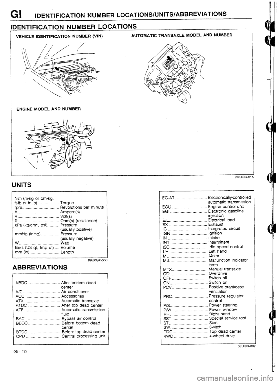
IDENTIFICATCON NUMBER LOCATIONS
I
VEHKZLE IDENTIFICATION NUMBER @‘IN) AUTOMATIC TRANSAXLE MODEL AND NUM8ER
ENGINE MODEL AND NUMBER
UNlTS
N-m (m-kg or cm-kg,
ft-lb or in-lb) . . . . . .._.......... Torque
rpm ._._..._.. . . . . . . .._.._.._. . .._. Revolutions per minute
A . . .._._._...__.._.._.._. .__...._. . . Ampere(s)
v .._.... .* .*... ..__.._...*. ..*. .*. ,. Volt(s)
0 I.._._............**..-.-*..-....... Ohm(s) (resistance)
Wa (kg/cm2, psi) . . . . . . . . . . Pressure
(usually positive)
mmlig (inHg) . . . . . . .._.._... Pressure
(usually negative)
w . . . ..*.....e*.-..-..-.....*.e..... Watt
liters (US qt, imp qt) .._. Volume
mm (in) ,_._.._._..._.,_. .~. . ..__ Length
89UOGX-006
ABBREVIATIONS
AB.DC ........................... After bottom dead
center
A/C _ .............................. Air conditioner
ACC ............................. Accessories
ATX ............................. Automatic transaxte
ATDC ......................... Afier top dead center
ATF .............................. Automatic transmission
ftuid
BAC ........................... Bypass air control
BBDC.. ......................... Before bottom dead
center
BTDC ........................... Before top dead center
CPU ............................. Central processing unit t EC-AT ........................... Ekctronically-controlled
automatic transmission
ECU ............................. Engine control unit
EGI ............................... Electronic gasotine
injection
EL ................................ Electricaf toad
EX ................................ Exhaust
IC ................................. Integrated circuit
IGN ............................... Ignition
IN ................................. Intake
tNT ............................... Intermittent
ISC ............................. Idle speed control
LH ................................ Left hand
M .................................. Motor
MIL ............................... Malfunction indicator
lamp
tb4TX. ............................. Manual transaxle
OD. ............................... Overdrive
OFF .............................. Switch off
ON ................................ Switch on PCV .............................. Positive crankcase
ventilation
PRC.. ............................ Pressure regulator
control
P/S ................................ Power steering
P/W .............................. Power wtndow
RH.. .............................. Right hand
SST ............................... Special service tool
ST .................................
Start
SW . . .............................. Switch
TDC. ............................. Top dead center
4VVD ............................. 4-wheel drive
Page 31 of 677
Bl INDEX
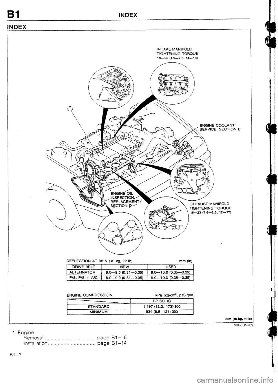
INDEX
INTAKE MANIFOLD
TIGHTENING TORQUE
19-25 (1.9-2.6, U-19)
EXHAUST MANIFOLD
TtGHTIEN!NG TORQUE
,3, 12-w-j
DEFLECTION AT 98 N (30 kg, 22 lb)
mm (in)
DRIVE BELT NEW USED
AlTERNATOR
8.0-9.0 (0.31-0.35) 9.0-l 0.0 (0.35-0.39)
PIS, P/S + AIC 1 8.0-9-O (0.31-O-35) 9.0-I 0.0 (0.35-0.39)
ENGINE COMPRESSION
STANDARD
MlNlMUM kPa (kglcm2, psi)-rpm
BP sol-lc
1,197 (12.2, 173)-300
834 (8.5, 121)-300
N-m (m-kg, ?t-It
cIz!f-mRl-71
1. Engine
Removal . . . . . . ..*..*-..............-....... page BY-- 6
Installation . . . . . . ..__. . . . . . . . .._...... . . . .
page B1-14
Bl-2
Page 42 of 677
REMOVAL Bl
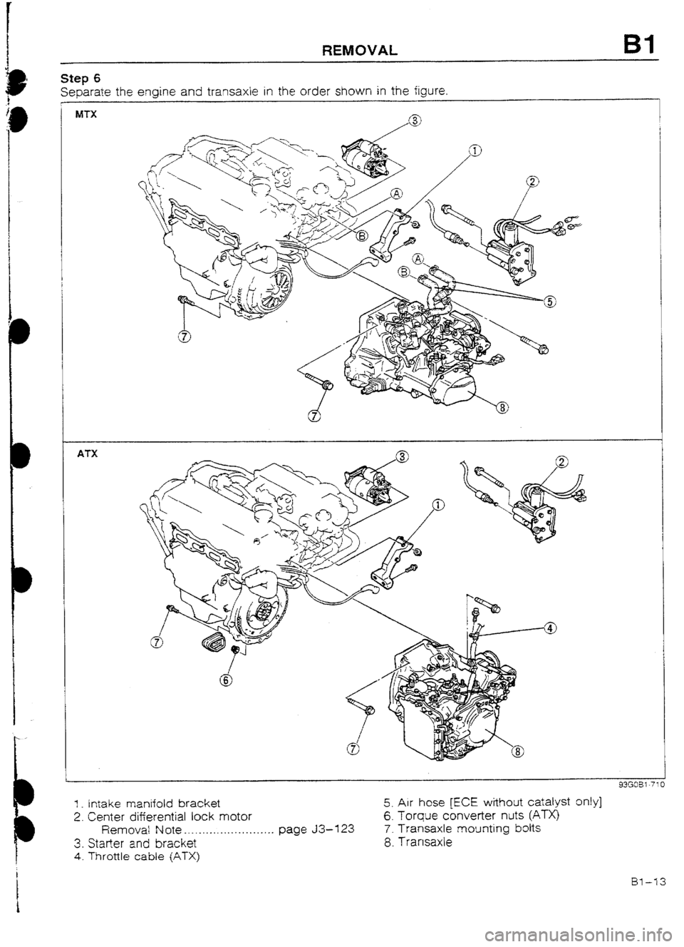
Step 6
Separate the engine and transaxle in the order shown in the figure,
MTX
ATX
43GX3i-71
1 _ Intake manifold bracket 5. Air hose [ECE without catalyst only)
2. Center differential lock motor 6. Torque converter nuts @TX)
Removal Note . . _. _. . . ._. . . . . . . . . . . . . _. page 33-l 23 7. Transaxle mounting bolts
3. Starter and bracket 8. Tramaxle
4. Throttle cable (ATX)
Bl-73
Page 43 of 677
Bl INSTALLATiON
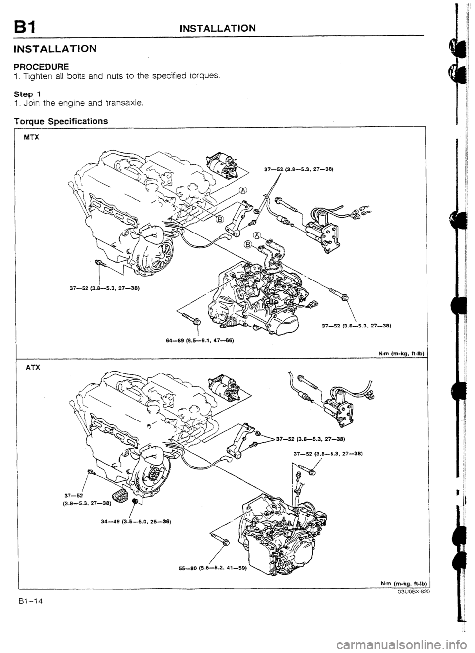
INSTALLATION
PROCEDURE
I. Tighten all bolts and nuts to the specified torques.
Step I
1. Join the engine and transaxle.
Toraue Snecifications
1- - -r--
MTX
37-52 (3.8-5.3, 27-38)
37-52 (3.8-5.3, 27-38)
ATX
64-89 (6 S-9 -1, 4746)
Nm (m-kg, ft-lb)
37-52 (3.8-5.3, 27-38)
55-80 (5.6-8.2, 41-59)
N-m (m-kg, ft-lb
51-14
Page 44 of 677
INSTALLATlON ES1
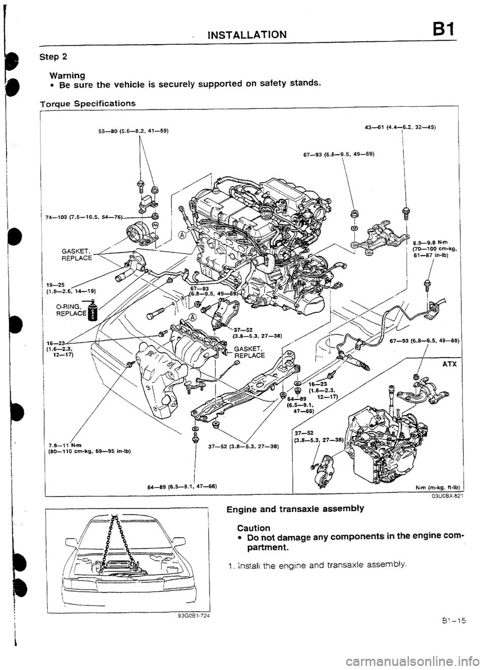
Step 2
Warning
l Be sure the vehicle is securely suppofied on safety stands.
Torque Specifications
I
I i 74-103 (7.5--10.5, 54-76)
/ 7.8-?I N-m
(80--flO cm-kg, 69-95 in-lb) 55-80 (5.fG-8.2, 41-59) 43-61 (4.4-6.2, 32-45)
I
1
I 64-89 (6.5-9.1, 4746) 67-93 (6.8-9.5, 49-69)
7 37-5x 27-38)
Engine and transaxle assembly
Caution
l Do not damage any components in the engine com-
partment.
1. Install the engine and transaxle assembly.
Page 45 of 677
Bl INSTALLATION
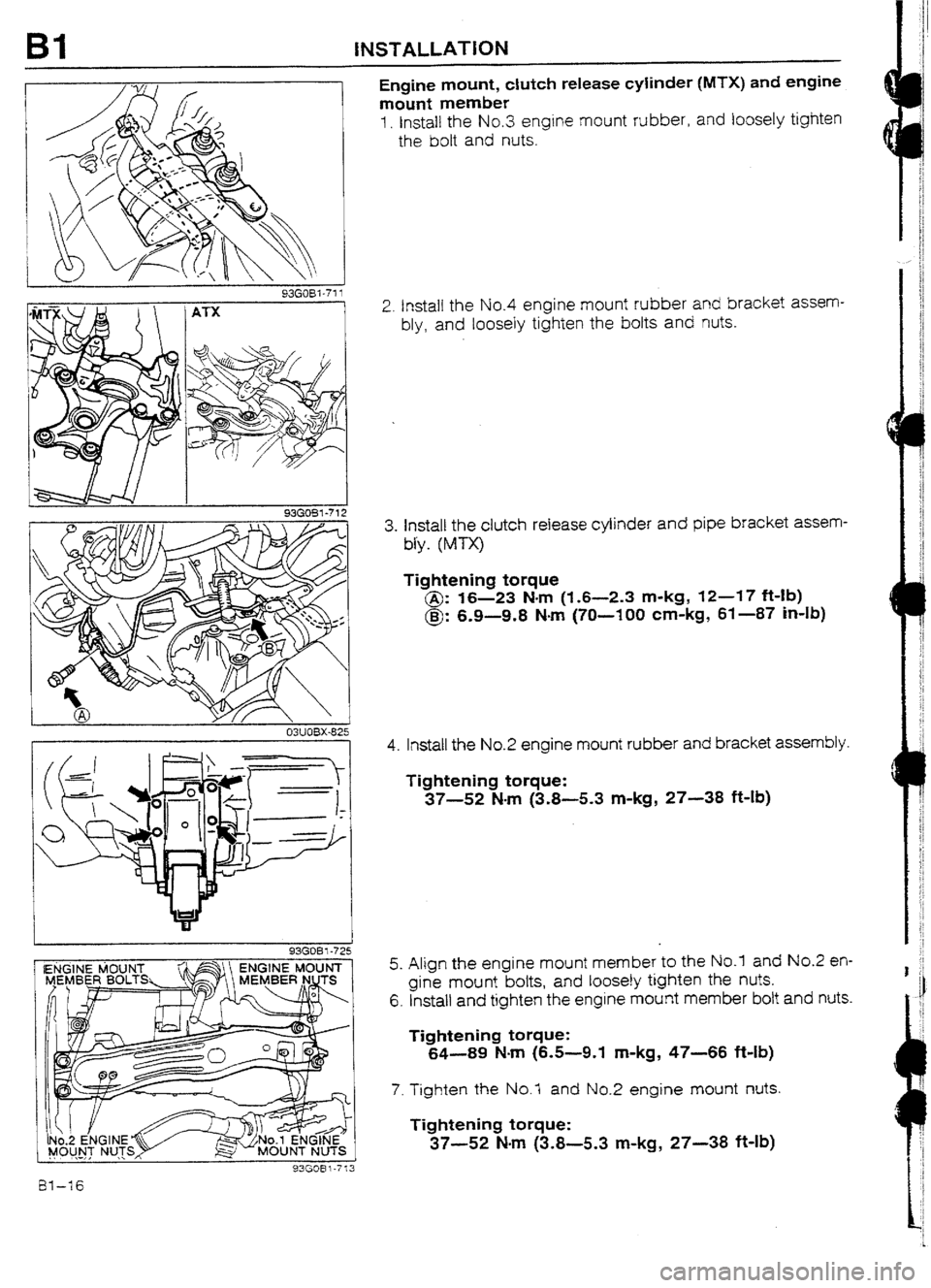
Engine mount, clutch release cyiinder (MTX) and engine
mount member
1. Install the No.3 engine mount rubber, and loosely tighten
the bolt and nuts.
2. Install the No.4 engine
mount rubber and bracket assem-
bly, and loosely tighten the
k~olts and nuts.
3. Install the clutch release cylinder and pipe bracket assem-
U-y.
(MTX)
Tightening torque
@: 16-23 Nm (1.6-2.3 m-kg, 12-47 ft-lb)
@: 6.9-9.8
N-m (70-100 cm-kg, 61-87 Mb)
I
93GOBl-72 J .-, , . . ,.
I
93GOBi-713
4. Install the No.2 engine mount rubber and bracket assembly.
Tightening torque:
37-52 Nm (3.8-5.3 m-kg, 27-38 ft-lb)
5. Align the engine mount member to the No.1 and No.2 en-
gine mount bolts, and loosely tighten the nuts.
6. Install and tighten the engine mount member bolt
and nuts.
Tightening torque:
64-89 N-m (6.5-9.1 m-kg, 47-66
ft-Lb)
7. Tighten the No.7 and No.2 engine mount nuts.
Tightening torque:
37-52 Mm (3.8-5.3 m-kg, 27-38 ft.lb)
Page 46 of 677
INSTALLATlON
MTX 1 A-I-X
WUOBX-828
43GOBl-72t
Step 3
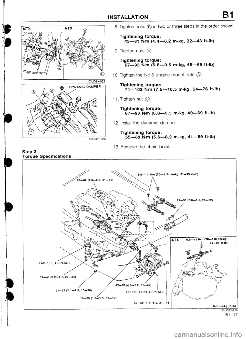
Torque Specifications 8. Tighten bolts @ in two or three steps in the order shown.
Tightening torque:
43-61 N-m (4.4-6.2 m-kg, 32-43 ft-lb)
9. Tighten nuts @J.
Tightening torque:
67-93 N-m (6.8-9.5 m-kg, 49-69 ft-lb)
IO. Tighten the No.3 engine mount nuts 0.
Tightening torque:
74-103 Nom (7,5--f0,5 m-kg, 54-76 ft-lb)
Ii. Tighten nut @.
Tightening torque:
67-93 N-m (6.8-9.5 m-kg, 49-69 ft-lb)
12. Install the dynamic damper.
Tightening torque:
55-W N-m (5.6-8.2 m-kg, 41-59 ft-Ib)
13. Remove the chain hoist.
6.9-11 N-m (70-l 10 cm-kg, 63-95 in-lb)
-8-3.1, 20-22)
&TX 6.9-11 N-m (70-130 cm-kg,
b 6% -95 in-lb) /
42-57 (4.3~5.8,31142)
21-27 (2.1-2.8, 15-20)
COTTER PIN, REPLACE
16-23 (1.6L2.3, Q-17)
N-m {m-kg, ft-tb
03UOBX-8:
Page 47 of 677
81 INSTALLATION
93GOBl-714
I 93E082-061
i 03UOBX-848
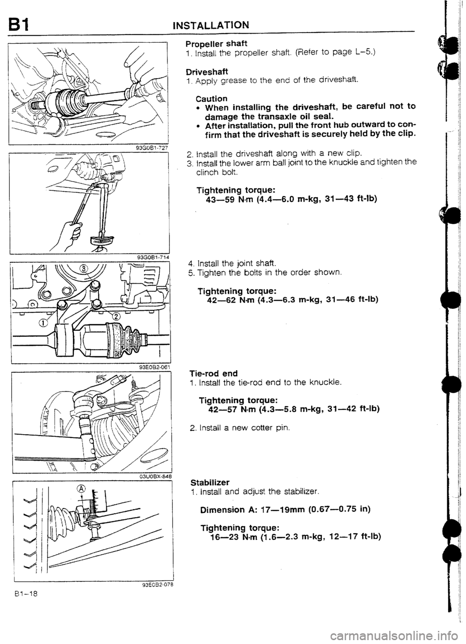
Propeller shaft
1. Install the propeller shaft. (Refer to page l-5.)
Driveshaft
I. Apply grease to the end of the driveshafi.
Caution
l When installing the driveshaft, be careful not to
damage the transaxle oil seal.
l After installation, pult the front hub outward to con-
firm that the driveshaft is securely held by the cIip.
2. Install the driveshaft along with a new clip.
3. fnstall the lower arm ball joint to the knuckle and tighten the
ciinch bolt.
Tightening torque:
43-59 Nm (4.4-6.0 m-kg, 31-43 ft-lb)
4. Install the joint shaft.
5. Tighten the bolts in the order shown.
Tightening torque:
42-62 Nom (4.3-6.3 m-kg, 31-46 f&lb)
Tie-rod end
1. InstaIl the tie-rod end to the knuckle.
Tightening torque:
42-57 N-m (4.3-5.8 m-kg, 31-42 ft-lb)
2. Install a new cotter pin.
Stabilizer
I. install and adjust the stabilizer.
Dimension A: i7-19mm (0.67-0.75 in)
Tightening torque:
16-23 Nm (l-6-2.3 m-kg, 12-17 Mb)
I
I