torque MAZDA 232 1990 Suplement User Guide
[x] Cancel search | Manufacturer: MAZDA, Model Year: 1990, Model line: 232, Model: MAZDA 232 1990Pages: 677, PDF Size: 61.19 MB
Page 48 of 677
--
D
b
D
1
I
1
(
I
INSTALLATION Bl
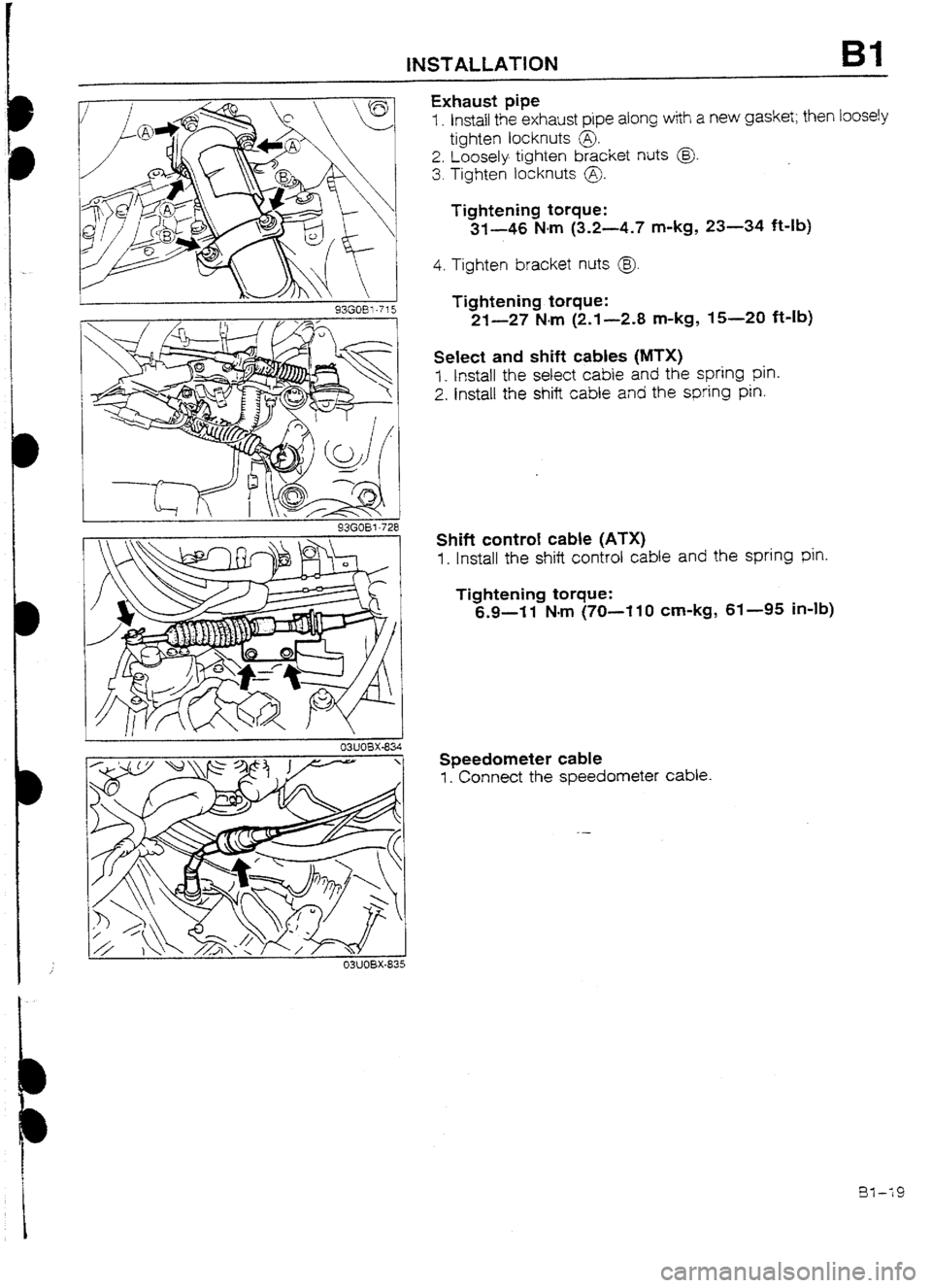
Exhaust pipe
I. Instail the exhaust pipe along with a new gasket; then loosely
tighten locknuts @.
2. Loosely tighten bracket nuts @
3. Tighten locknuts 0.
Tightening torque:
3f-46 N-m (3.2-4.7 m-kg, 23-34 f&lb)
4. Tighten bracket nuts @.
Tightening torque:
21-27 Mm (2.1-2.8 m-kg, 15-20 ft-Ib)
Select and shift cables (MTX)
7 _ Install the select cable and the spring pin.
2. Install the shift cable and the spring pin.
03UO8X-835
Shift control cable (ATX)
1. Install the shift control cable and the spring pin.
Tightening torque:
6.9-l 1 Nom (70-l 10 cm-kg, 61-95 in-lb)
Speedometer cable
1. Connect the speedometer cable.
t
Page 50 of 677
I)
I)
i
INSTALLATION Bl
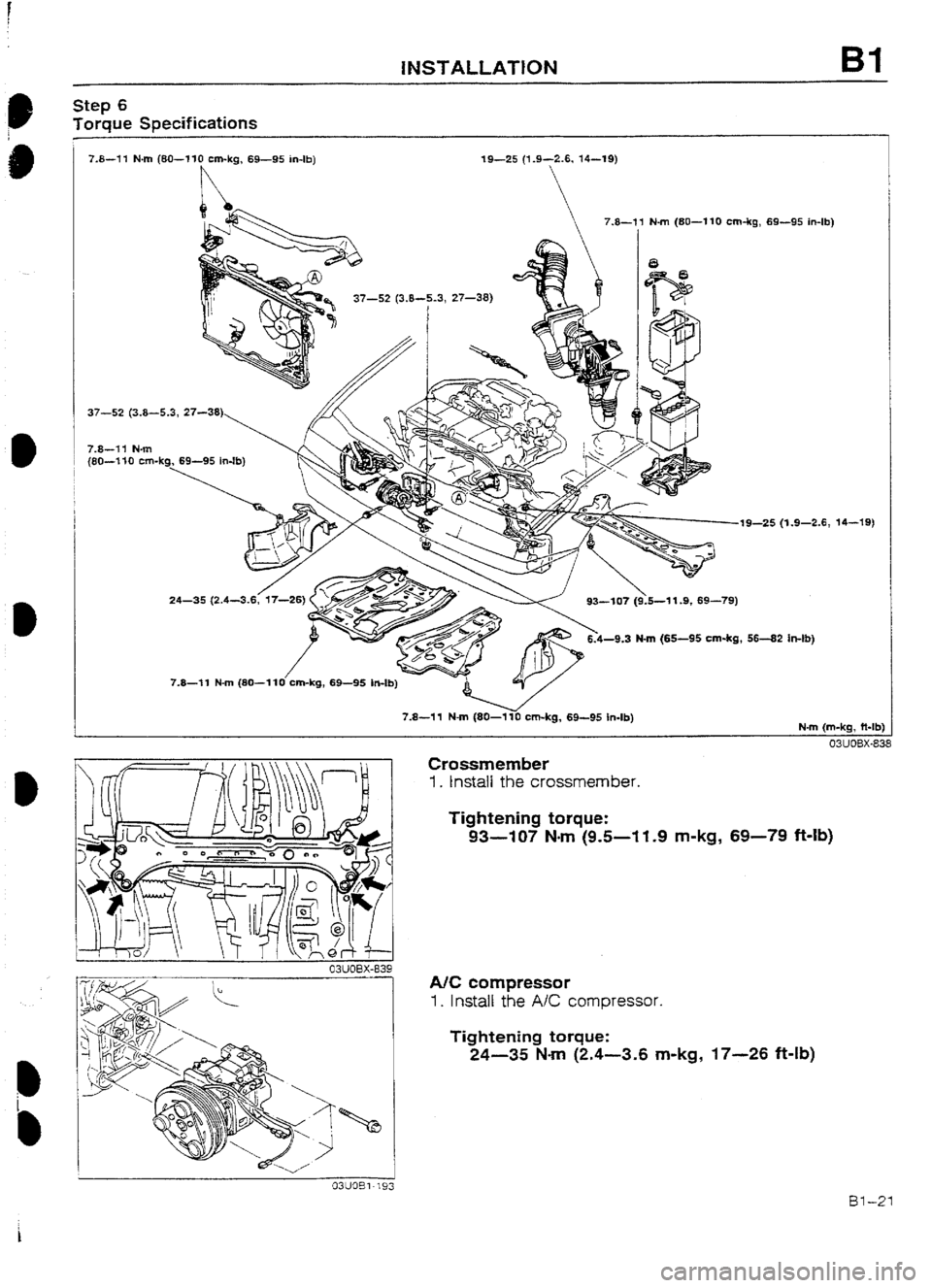
Step 6
Torque Specifications
7.8-11 N-m (8U---110 cm-kg, 69-95 in-lb) 19-25 (1.9-2.6, 14-19)
37-S (3.8-5.3, 27-38)
7.8-71 N-m
(80-l 10 cm-k
19-25 (1.9-2.6, 14-
5-1 1.9, 69-79)
-9.3 N-m (65-95 cm-kg, 56-82 h-lb) -79)
7.8-11 N-m (80-1~0 cm-kg, 69-95 in-lb)
a3uar3x-839
Crossmember
1. tnstali the crossmember.
Tightening torque:
93-107 Nm (9.5-I 1.9 m-kg, 69-79 f+lb)
NC compressor
1. Install the A/C compressor.
Tightening torque:
24-35 N-m (2.4-3.6 m-kg, 17--26 ft-lb)
Bl-21
Page 51 of 677
Bl INSTALLATION
93GOE 1-73;
03UOBX-84
. .
‘, .
L .G,
. . ‘?.
- -. _ .:
.L ‘.. :-.:
.-_: _. _, _-
.
-_
. :
Cl :- . .
: .._.
. . ._-
;: , ‘. ’
,.. .- -
. ‘L,
93GO3 l-73’
-DEFLECTiON CHfiCKIN:
g3GOBj-717
Bl-22
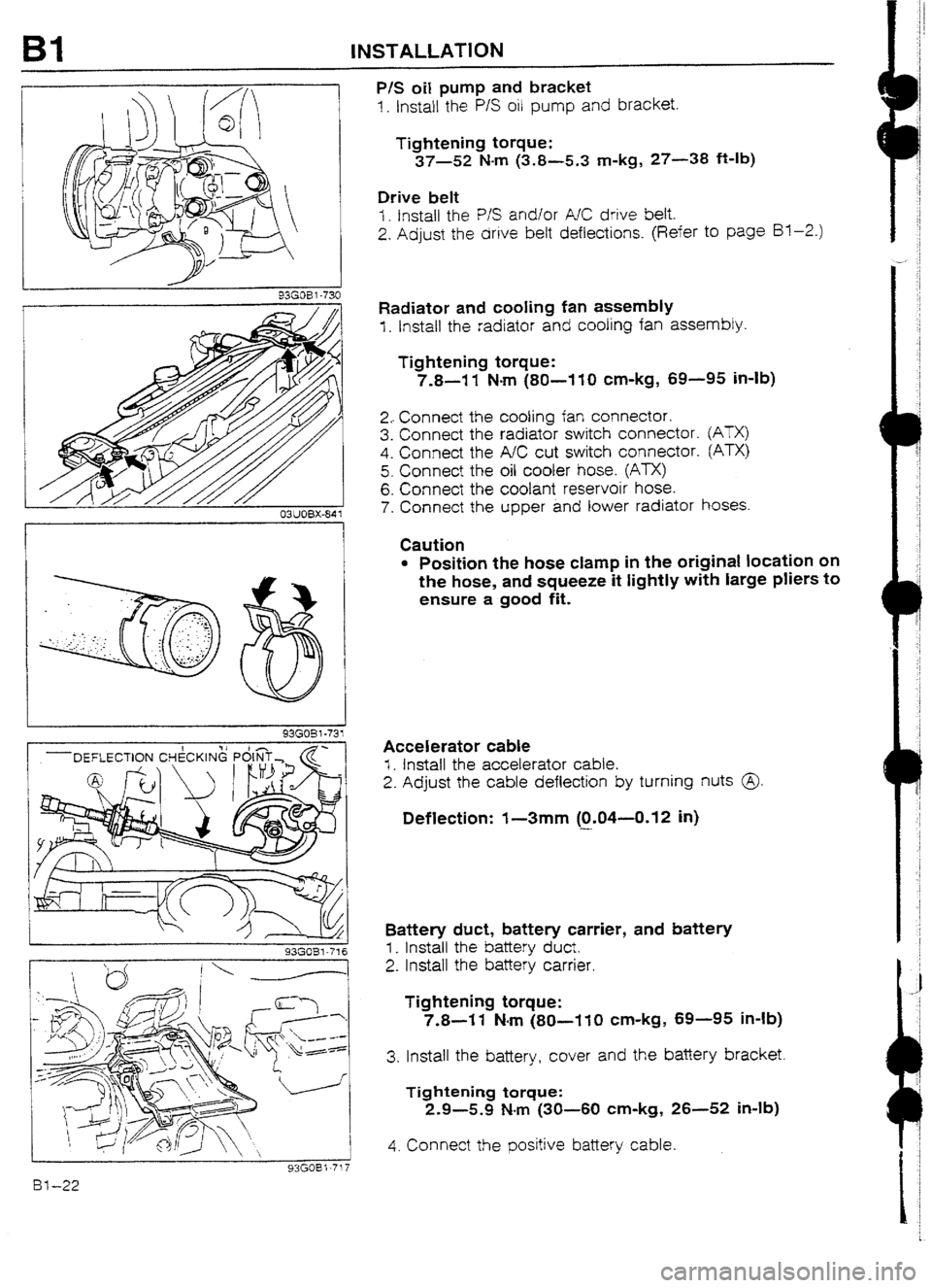
P/S oil pump and bracket
1. Install the P/S oil pump and bracket.
Tightening torque:
37-52 N-m (3.8-5.3 m-kg, 27-38 ft-lb)
Drive belt
I. fnstall the P/S and/or A/C drive belt.
2. Adjust the drive belt deflections. (Refer to page Bl-2.)
Radiator
and cooling fan assembly
f . Install the radiator and cooling fan assembly.
Tightening torque:
7.8-I 1 N-m (80-I 10 cm-kg, 69-95 in-lb)
2.. Connect the cooling fan connector.
3. Connect the radiator switch connector.
4. Connect the A/C cut switch connector.
5. Connect the oil cooler hose. (ATX)
6. Connect the coolant reservoir hose.
7. Connect the upper and lower radiator
@TX)
Pm
hoses.
Caution
l Position the hose clamp in the original location on
the hose, and squeeze it tightly with large pliers to
ensure a good fit.
Accelerator cable
I. Install the accelerator cable.
2. Adjust the cable deflection by turning nuts @
Deflection: I-3mm (0.04--0.12 in)
-
Battery duct, battery carrier, and battery
I_ install the battery duct.
2. Install the battery carrier.
Tightening torque:
7.8-I 1 N-m (80-110 cm-kg, 69-95 in-lb)
3. Install the battery, cover and the battery bracket.
Tightening torque:
2.9-5.9 N-m (30-60 cm-kg, 26-52 in-lb)
4. Connect the positive battery cable.
Page 52 of 677
INSTALLATION Bl
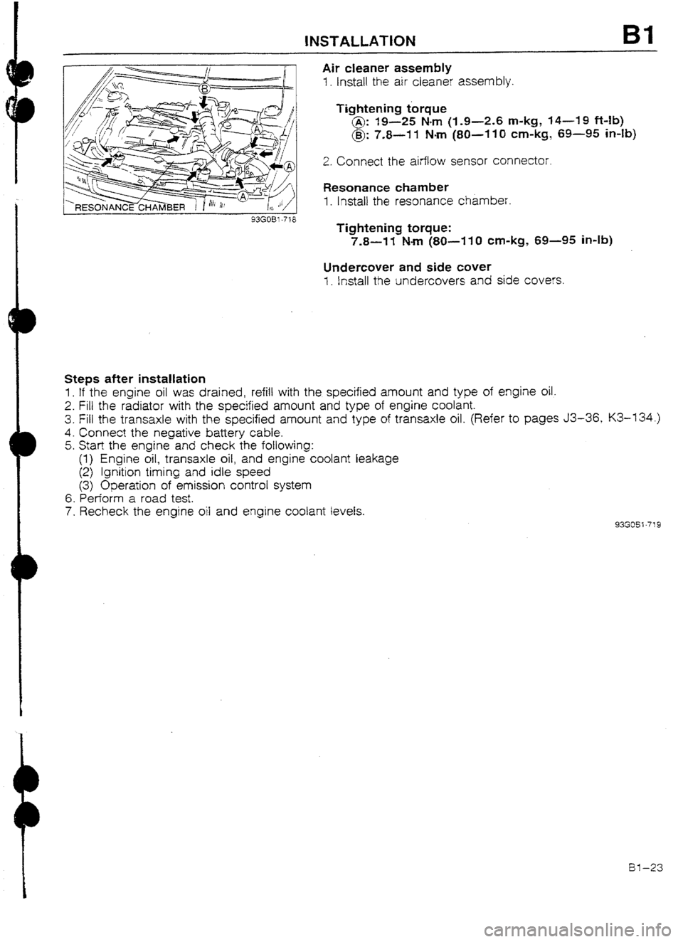
Air cleaner assembly
1. Install the air cleaner assembly.
Tightening torque
@: 19-25 Nm (I-9-2.6 m-kg, 14-19 Mb)
@: 7.8-11 Nm (80~-110 cm-kg, 69-95 in-lb)
2. Connect the airflow sensor connector.
Resonance chamber
1. lnstail the resonance chamber.
Tightening torque:
7.8-W Nm (SO-11 0 cm-kg, 69-95 in-lb)
Undercover and side cuver
1. install the undercovers and side covers.
Steps after installation
1. If the engine oil was drained, refill with the specified amount and type of engine oil.
2. Fill the radiator with the specified amount and type of engine coolant.
3. Fill the transaxle with the specified amount and type of transaxle oil. (Refer to pages J3-36, K3-134.)
4. Connect the negative battery cable.
5. Start the engine and check the following:
(1) Engine oil, transaxle oil, and engine coolant leakage
(2) Ignition timing and idle speed
(3) Operation of emission control system
6. Perform a road test.
7. Recheck the engine oil and engine coolant levels.
93GOSi-719
al-23
Page 55 of 677

B2 INDEX
INDEX
~IMIY~ULU
TIGHTENING TORQUE
19-25 (1.9-2.6, 14-19)
/5--l ENGINE COMPRESSION
STANDARD
MINIMUM kPa (kglcm2, psi)-rpm
BP Turbo
I
1,059 (10.8, 1543-300
1 i-85 (8.0, 114)-300
EXHAUST MANlFOt
TIGHTENING TORQUE
DEFLECTION AT 98 N (IO kg, 22 Ib)
mm (in)
DRIVE BELT 1 NEW USED
ALTERNATOR 1 8.0-9.0 (0.31-U.35) 9.0-I 0.0 (0.35-U.39)
P/S, P/S + AIC ( 8.U-9.0 [O-31--0.35) 9.0-10.0 (0.35-0.39) 3826 3.9-A.?, -28134)
1. Engine
Removal -*-...-..I-*.* . ..wm._..... * e-e... -. page B2--I 2
Engine stand mounting ._.....__... page B2-20
Engine stand dismounting . . . . . . . page B2-21
Installation _ . . . . . . . . . . . . , . . _. . . . . . _. . . . . . . . , page EQ-23
BZ-2
Page 64 of 677
D
D
SUPPLEMENTAL SERVICE iNFORMATION, COMPRESSION 82
SUPPLEMENTAL SERVICE INFORMATION
The following points in this section are changed in comparison with Workshop Manual [Europe (7 203~IO-899,
Australia (I 204-1 U-89F) 1.
Compression
l Inspection
Engine
l Removal
l Engine stand mounting
l Engine stand dismounting
l Ins:attaIion 93GQ32-77 I
COMPRESStON
If the engine exhibits low power, poor fuel economy, or poor idle, check the following:
1. Ignition system (Refer to Section G.)
2. Compression
3. Fuel system (Refer to Section F3.)
93G032-774 93GO32-712
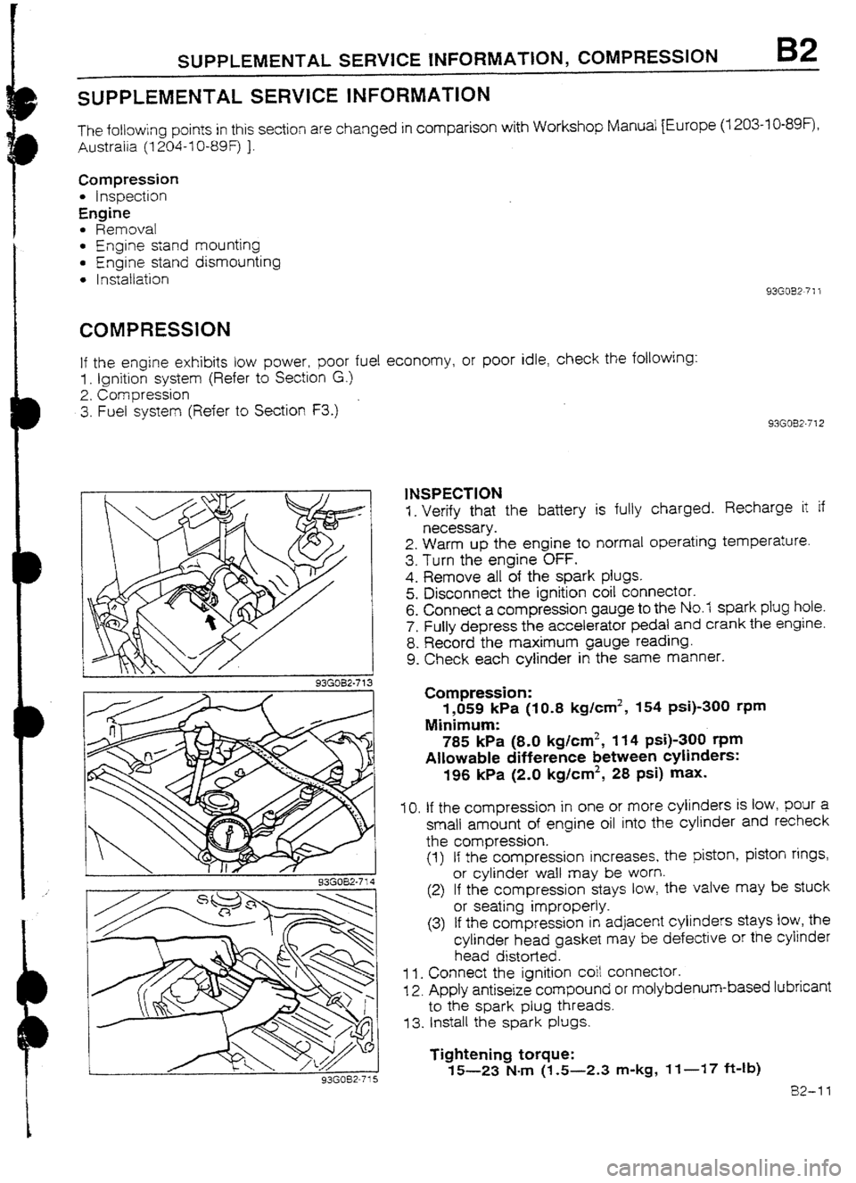
1NSPECTION
1. Verify that the battery is fully charged. Recharge it if
necessary.
2. Warm up the engine to normal operating temperature.
3. Turn the engine OFF.
4. Remove all of the spark plugs.
5. Disconnect the ignition coil connector.
6. Connect a compression gauge to the No.7 spark plug hole.
7. Fully depress the accelerator pedal and crank the engine.
8. Record the maximum gauge reading.
9. Check each cylinder in the same manner.
Compression:
1,059 kPa (IO.8 kg/cm2, 154 psi)-300 rpm
Minimum:
785 kPa (8-O kg/cm2, 114 psi)-300 t-pm
Allowable difference between cylinders:
196 kPa (2.0 kglcm2, 28 psi) max.
IO. If the compression in one or more cylinders is low, pour a
small amount of engine oil into the cylinder and recheck
the compression.
(1) If the compression increases, the piston, piston rings,
or cylinder waII may be worn.
(2) If the compression stays tow, the valve may be stuck
or seating improperly.
(3) If the compression in adjacent cylinders stays low, the
cylinder head gasket may be defective or the cylinder
head distorted.
1 I. Connect the ignition coit connector.
12. Apply antiseize compound or molybdenum-based lubricant
to the spark plug threads.
73. Install the spark plugs.
Tightening torque:
15-23 N-m (1.5-2.3 m-kg, If-17 ft-Ib)
82-11
Page 74 of 677

ENGlNE STAND DISMOUNTING B2
ENGiNE STAND DISMOUNTING
PROCEDURE
1. Remove the engine from the SST (engine stand).
2. Remove the SST (engine hanger) from the engine.
3. Install the parts shown in the figure.
4. Tighten the parts to the specified torques.
Torque Specifications
f&n (m-kg, ft-lb)
93GOB2-75
Water Inlet Pipe
1. Remove ail foreign material from the water inlet pipe mount-
ing surfaces.
2. Install a new gasket and the water inlet pipe.
Tightening torque:
f9-25 Nm (1.9-2.6 m-kg, 14-19 ft-lb)
93GOB2-753
82-21
Page 75 of 677

B2 ENGINE STAND DISMOUNTING
93GOB2-7%
93AOB2-077
05WOBX-25
82-22 Water Bypass Pipe
1. Apply a small amount of engine coolant to the new O-ring.
2. install the O-ring on the pipe.
3. InstaIi the water bypass pipe.
A/C Compressor Bracket (if equipped)
1. Install the A/C compressor bracket.
Tightening torque
@: 19-25 N&m (1.9-2.6 m-kg, 14-19 ft-lb)
@: 37-52 Nom (3.8-5.3 m-kg, 27-38 ft-fb)
Exhaust Manifold and Turbocharger Assembly
I= Remove all foreign material from the exhaust manifold con-
tact surfaces.
2. Install a new gasket.
3. Instatl the exhaust manifold and turbocharger assembly.
Tightening torque:
38-46 N-m (3.9-4.7 m-kg, 28-34 ft-lb)
4. Connect the water hose to the water bypass pipe.
5. Connect the water hose and the oil pipe to the cylinder
block.
Tightening torque
@: 12-18 N-m (I -2-l .8 m-kg,
6. Connect the oil return hose to the oi 8.7-13 ft-lb)
I pan.
Exhaust Manifold Insulator
1. Install the exhaust manifold insulator.
Tightening torque:
7.8-I 1 Mm (80-I IO cm-kg, 69-95 in-lb)
Page 76 of 677
INSTALLATION B2
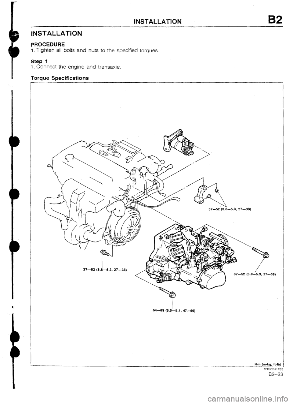
PROCEDURE
1. Tighten a/ b&s and nuts to the specified
torques.
Step 1
I. Connect the engine and transaxie.
Torque Specifications
-38)
M-89 (6.5L9.l) 47-66)
Page 77 of 677
B2 INSTALLATION
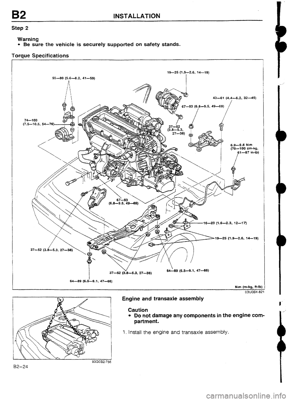
Step 2
Warning
l Be sure the vehicle is securely supported on safety stands.
Torque Specifications
19-S (1.9-2.6, 14-l 9)
55-99 (5.6-8.2, 41-59)
I
74-2 03
(7,5-10.5, 54-76
6.9-9.8 N-m
16-23 (T.6-2.3, 12-17)
19-26 (1.9-2.6, 14-l 9)
9 (6.5-9.1, 4766)
64-89 (6.&9.*, 47-56)
Engine and transaxle assembly
Caution
l Do not damage any camponents in the engine com-
partment.
I. Install the engine and transaxle assembly.
93G052-756 B2-24