heater MAZDA 232 1990 Workshop Manual Suplement
[x] Cancel search | Manufacturer: MAZDA, Model Year: 1990, Model line: 232, Model: MAZDA 232 1990Pages: 677, PDF Size: 61.19 MB
Page 21 of 677

A PRE-DELIVERY INSPECTION
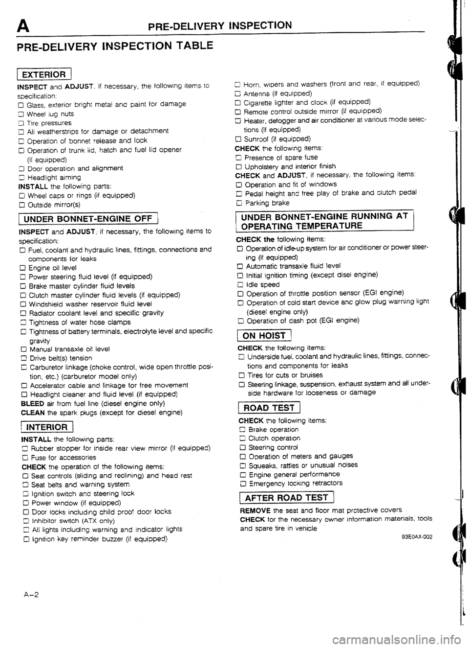
PRE-DELIVERY INSPECTION TABLE
pieziG-
INSPECT and ADJUST, if necessary, the following Items to
specification:
D Glass, exterior bright metal and paint for damage
Cl Wheel tug nuts
9 Trre pressures
LII All weatherstrips for damage or detachment
Z Operation of bonnet release and lock
D Operation of trunk lid, hatch and fuel lid opener
(it equipped)
3 Door operation and alignment
5 Headlight aiming
INSTALL the following parts:
D Wheel caps or rings (if equipped)
D Outside mirror(s)
[ UNDER BONNET-ENGINE OFF )
INSPECT and ADJUST, if necessary, the foIlowIng items to
specification:
Cl Fuel, coolant and hydraulrc lines, fittings, connections and
components for leaks
Cl Engine oil level
0 Power steering fluid level (if equipped)
D Brake master cylinder fluid levels
0 Clutch master cylinder fluid levels (if equipped) q
Windshield washer reservoir fluid level
D Radiator coolant level and specific gravity
Ll Tightness of water hose clamps
I3 Tightness of battery terminals, electrolyte level and specific
gravity
c) Manual transaxle oit level
D Drive belt(s) tension
C; Carburetor linkage (choke control, wide open throttle posi-
tion, etc.) (carburetor model only)
D Accelerator cable and linkage for free movement
D Headlight cleaner and fluid level (if equipped)
BLEED air from fuel line (diesel engine only)
CLEAN the spark plugs (except for diesef engine)
piicis-1
INSTALL the foflowing parts:
C Rubber stopper for inside rear view mirror (if equipped)
c! Fuse for accessories
CHECK the operation of the following items:
Cl Seat controls (sliding and redining) and head rest
ci Seat belts and warnrng system
Z! Ignition swrtch and steering lock
III Power window {if equipped)
0 Door locks including child proof door locks
0 Inhibitor switch
(ATX only)
Z All lights including warning and indicator lights
0 Ignrtron key reminder buyer (if equipped) Cl Horn, wipers and washers (front and rear, if equipped)
D Antenna (if equipped} q
Cigarette lighter and clock (if equipped)
I2 Remote controt outside mirror
(if equipped) q
Heater, defogger and air conditioner at various mode selec-
tions (if equipped)
c3 Sunroof (if equipped)
CHECK
the fotiowing items: q
Presence of spare fuse
c3 Upholstery and interior finish
CHECK and ADJUST, if necessary, the following items:
Cl Operation and fit of windows
D Pedal height and free ptay of brake and clutch pedal
Cl Parking brake
i UNDER BONNET-ENGtNE RUNNING AT ]
1 OPERATtNG TEMPERATURE
CHECK the following items:
Cl Operation of idle-up system for air conditioner or power steer-
ing (if equipped)
13 Automatic transaxle fluid level
D Initial ignition timing
(except disel engine) q
Idle speed
El Operation of throttle position sensor (EGI engine)
13 Operation of cold start device and glow plug warning light
(diesel engine only)
D Operation of dash pot [EGI engine)
t
ON HOtST 1
CHECK the following items:
U Underside fuel, coolant and hydraulic lines, fittings, connec-
tions and components for leaks q
Tires for cuts or bruises
Cl Steering linkage, suspension, exhaust system and all under-
side hardware for
looseness or damage
1 ROAD TEST 1
CHECK the foliowing items:
II Brake operation
D Clutch operation
0 Steering control
c3 Operation of meters and gauges
0 Squeaks, rattles or unusual noises q
Engine general performance
c3 Emergency Iocking retractors
rAFTER ROAD TEST 1
REMOVE the seat and floor mat protective covers
CHECK for the necessary
owner information materials, tools
and spare tire in vehicle
93EOAX-002
A-2
Page 37 of 677

Bl REMOVAL
Step 3
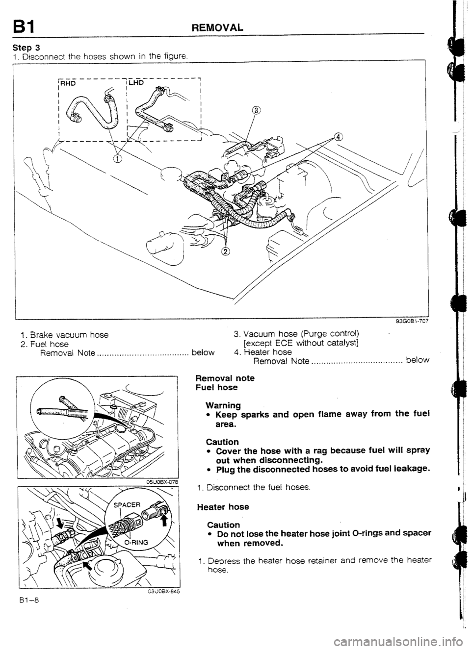
1. Disconnect the hoses shown in the figure.
I
-----a _--w---
/
/I /
ti
93GOB7 -707
1. Brake vacuum hose 3. Vacuum hose (Purge control)
2. Fuel hose [except ECE without catalyst]
Removal Note . . . . . . . . . .*a . . . . . . . . *.* . . . . . . . . . . a-.. below 4. Heater hose
OWOBX-078
Removal Note *...,.....*............-.I..*.*.*.-*- below
Removal note
Fuel hose
Warning
l Keep sparks and open flame away from the fuel
area.
Caution
l Cover the hose with a rag because fuel will spray
out when disconnecting.
l Plug the disconnected hoses to avoid fuel leakage.
1. Disconnect the
fuel hoses.
Heater hose
Caution
l Do not lose the heater hose joint O-rings and spacer
when removed.
1. Depress the heater hose retainer and remove the heater
hose.
Page 68 of 677

REMOVAL B2
_. OWOBX-07I
03UOBX-845
SteD 4 Removal note
Fuel hose
Warning
l Keep sparks and open flame away from the fue!
area.
Caution
l Cover the hose with a rag because fuel will spray
out when disconnecting.
l Plug the disconnected hoses to avoid fuel leakage-
1. Disconnect the fuel hoses.
Heater hose
Caution
l Do not lose the heater hose joint O-rings and spacer
when removed.
1. Depress the heater hose retainer and remove the heater
hose.
GASKET, REP
OTTER PIN, REPU\CE
91Gr-P7-771 J
-.,-1w- IL .
1. Speedometer cable 6. Driveshafts
2. Select and shift cables Removal Note ._.....*., * . . ..- *...- I..... page BZ-16
3. Front exhaust pipe 7. Propeiler shaft
4. Stabilizer Removal Note . . . . . . . _ . , . . . _. . . . . . . . . _. . . . . page L- 5
5. Tie-rod end
Removal Note . . . . . . . . . . . . . . . . . . . . . . . .._. page BZ-16
B2-15
Page 95 of 677

E OUTlANE
TWO-STAGE THERMOSTAT (BP DOHC TURBO)
MAIN VALVE
SINGLE-STAGE THERMOSTAT
(AMBIENT fEMP. -20% (4*f))
NTRANCE PORT TEMP
GINE EXIT PORT TEMP.
- 100 km/h
60 kndh
(63 mph) ~~~~~ (38 mph)
TWO-STAGE THERMOSTAT
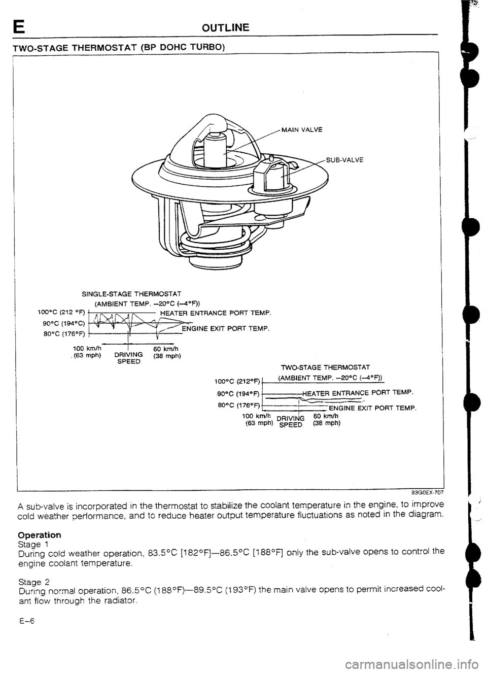
A sub-valve is incorporated in the thermostat to stabilize the coolant temperature in the engine, to improve
cold weather performance, and to reduce heater output temperature fluctuations as noted in the diagram.
Operation
Stage 1
During cold weather operation, 83.5*C [182°F]-86.50C [t 88OF] only the sub-valve opens to control the
engine coolant temperature.
Stage 2
During normal operation, 86.5OC (1 88°F)-89.50C (I 93OF) the main valve opens to permit increased coul-
an: flow through the radiator.
E-6
Page 121 of 677

F2 OUTUNE
OUTLINE OF CONSTRUCTION
The fuel and emission control system of the new 323 4WD model is basically the same as that of the new
323 2WD modet; however, a turbocharger and knock control system are added to the BP TURBO model
and the fuel tank is designed
with separate right and left sections due to the installation of the propeller shaft
for the 4-wheel-drive system. A transfer pump is also equipped to pump the fuel from the left
to the right
(fuel pump side) section of the fuel tank.
The major points of difference between the 2WD model and 4WD model are as shown below.
93GOF2-705
Difference
Component 2WD 4WD
BP SUHC BP OOHC BP SOHC BP TURBU Remark
INTAKE AG! 1 Resonance duct 0 0 0 - -
SYSTEM
Resonance chamber 0
0 G -
VICS .-
ui- - -
Turbocharger - - -
0 Refer to page
FZ-12
I ntercooler - - -
0 Refer to page FZ-14
Air bypass valve - - -
0 Refer to page F2-14
FUEL SYSTEM Fuel pump control - - -
0 Refer to page F2-16
Transfer pump - -
0 0 Refer to page F2-18
Operating time for BP
Pressure regulator control 0 0 0 0
TURBO is different
(Refer to page F2-23)
Fuel pump reststorlrelay - - -
0 Refer to page F2-18
EVAPORATIVE
EMISSION
Fuel vapor vatve - -
CONTROL 0 0 Refer to page F2-16
SYSTEM
CONTROL
SYSTEM Point type
0 0
Throttle sensor 0 (MTX) -
-
Variable type - -
0 W-x) 0
Without heater
0 0 0 -
Oxygen sensor F
With heater - -
- 0 Refer to page F2-23
Water thermoswitch (on radiator)
-
Knock control system -
Overboost wami ng buzzer -
Turbocharge Indicator - -
C @TX) - NC cut-off system
- - 0
Refer to page F2-22
- -
0 Refer to page F2-21
- - 0 Refer to page F2-21
93GOF2-706
Page 140 of 677
![MAZDA 232 1990 Workshop Manual Suplement CONTROL SYSTEM F2
t OXYGEN SENSOR [BP TURBO]
I
CERAMlC HEATER
93GOF2-733
Because the temperature of the exhaust gas is inherently low in turbocharged engines, the BP Turbo model
uses a rapid hea MAZDA 232 1990 Workshop Manual Suplement CONTROL SYSTEM F2
t OXYGEN SENSOR [BP TURBO]
I
CERAMlC HEATER
93GOF2-733
Because the temperature of the exhaust gas is inherently low in turbocharged engines, the BP Turbo model
uses a rapid hea](/img/28/57056/w960_57056-139.png)
CONTROL SYSTEM F2
t OXYGEN SENSOR [BP TURBO]
I
CERAMlC HEATER
93GOF2-733
Because the temperature of the exhaust gas is inherently low in turbocharged engines, the BP Turbo model
uses a rapid heating ceramic heater to detect the air/fuel ratio,
PRESSURE REGULATOR CONTROL SYSTEM [BP TURBO]
PRESSURE
REGULATOR
I SOLENOID VALVE
(PRESSURE REGULATOR CONTROL)
FUEL
+ (FROM
DELIVERY PIPE1
II
FUEL INJ I
RELAY
(MAIN REU\Y)
I
II Ir
-__. _ - -’ VACUUM
CT0 DYNAMIC
Ill
CHAMBER)
BATTERY -
c
FUEL
(TO FUEL TANK)
nme*rn -.-a
To prevent percolation of the fuel during hot restart idle, vacuum to the pressure regulator k cut for 180
sec., and the fuel injection pressure is increased to slightly more than 284 kPa (2.90 kg/cm’, 41.2 psi).
Operating condition
l Coolant temperature: Above 90°C (194OF)
l Intake air temperature: Above 58OC (136OF)
g No-load condition
FZ-23
Page 185 of 677
![MAZDA 232 1990 Workshop Manual Suplement F2 CONTROL SYSTEM
93GOF2-79; 2
93GOF2-793
93GOFZ794
1
OXYGEN SENSOR [BP TURBO]
Inspection
Sensor
1. Warm up the engine to normal operating temperature.
2. Disconnect the oxygen sensor connect MAZDA 232 1990 Workshop Manual Suplement F2 CONTROL SYSTEM
93GOF2-79; 2
93GOF2-793
93GOFZ794
1
OXYGEN SENSOR [BP TURBO]
Inspection
Sensor
1. Warm up the engine to normal operating temperature.
2. Disconnect the oxygen sensor connect](/img/28/57056/w960_57056-184.png)
F2 CONTROL SYSTEM
93GOF2-79; 2
93GOF2-793
93GOFZ794
1
OXYGEN SENSOR [BP TURBO]
Inspection
Sensor
1. Warm up the engine to normal operating temperature.
2. Disconnect the oxygen sensor connector.
3. Connect a voltmeter to the oxygen sensor terminal @.
4. Run the engine at 4,500 rpm untiI the voltmeter indicates
approx. 0.7V.
5. Increase and decrease the engine speed suddenly and
measure the vottage.
Voltage
Engme speed Voltage (v-)
Decelerating o-0.4
Accelerating 0.5-l .o 6. Connect the
SSTs to the diagnosis connector.
7. Set the system selector select switch to 1 and the test switch
to 02 MONITOR.
8. Increase the engine speed to
between 2,000 and 3,000
rpm, and verify that the monitor lamp flashes for 10 seconds.
Specification:
Monitor lamp flashes more than 8 times/IO sec.
Heater 1. Disconnect the oxygen sensor connector.
2. Check resistance between oxygen sensor connector ter-
minals @ and 0.
Resistance: Approx.-6& [at 20°C (68OF)]
Replacement 1. Disconnect the oxygen connector. ’
2. Remove the oxygen sensor.
3. Install the new oxygen sensor and new washer.
4. Tighten the oxygen sensor to specified torque.
Tightening torque:
29-49 N-m (3-5 m-kg, 22-36 ft-tb)