key MAZDA 232 1990 Workshop Manual Suplement
[x] Cancel search | Manufacturer: MAZDA, Model Year: 1990, Model line: 232, Model: MAZDA 232 1990Pages: 677, PDF Size: 61.19 MB
Page 4 of 677

GENERAL INFORMATION
IMPORTANT INFORMATION ..................... GI- 2
BASIC ASSUMPTtONS ............................ a- 2
SAFETY RlSK
........................................ GI- 2
POSSBLE LOSS OF WARRANTY ............. GI- 2
WARNiNF ON LUBRICANTS
AND GREASES .................................... GI- 2
HOW TO USE THIS MANUAL.. .................. Gl- 3
PREPARATION ...................................... Gl- 3
REPAIR PROCEDURE ............................. Gl- 3
SYMBOLS
............................................. a- 4
NOTES, CAUTIONS, AND WARNINGS ....... Gl- 4
FUNDAMENTAL PROCEDURES ................. Gl- 4
PROTECTION OF THE VEHICLE .............. Gi- 4
A WORD ABOUT SAFETY ....................... Gl- 5
PREPARATION OF TOOLS
AND MEASURING EQUIPMENT ............. GI- 5
SPECIAL TOOLS
.................................... Gt- 5
REMOVAL OF PARTS
............................. GI- 5
DISASSEMBLY ...................................... Gi- 5
REASSEMBLY ....................................... Gl- 6
ADJUSTMENTS
..................................... GC- 7
RUBBER PARTS AND TUBING ................ Gl- 7
JACK AN5 SAFETY STAN5 POSITDNS .... Gl- 8
VEHICLE LIFT (Z-SUPPORT TYPE)
POSITIONS ............................................ GI- 8
TOWING .................................................. GL 9
IDENTIFICATION NUMBER LOCATIONS ..... GI-10
UNITS
..................................................... GI-I 0
ABBREVIATIONS ..................................... Gl-I 0
CAUTION ................................................ Gl-I 1
1NSTALLATtON OF A MOBlLE
TWO-WAY RADIO SYSTEM .................... GI-II
REMOVAL OF tGNIT1ON KEY ON
AUTOMATIC TRANSAXLE MODEL .......... Gl-11
ELECTRICAL TROUBLESHOOTlNG TOOLS GI-12
CAUTION WITH ELECTRICAL PARTS ........ Gl-13
03UGIX-001
Page 14 of 677

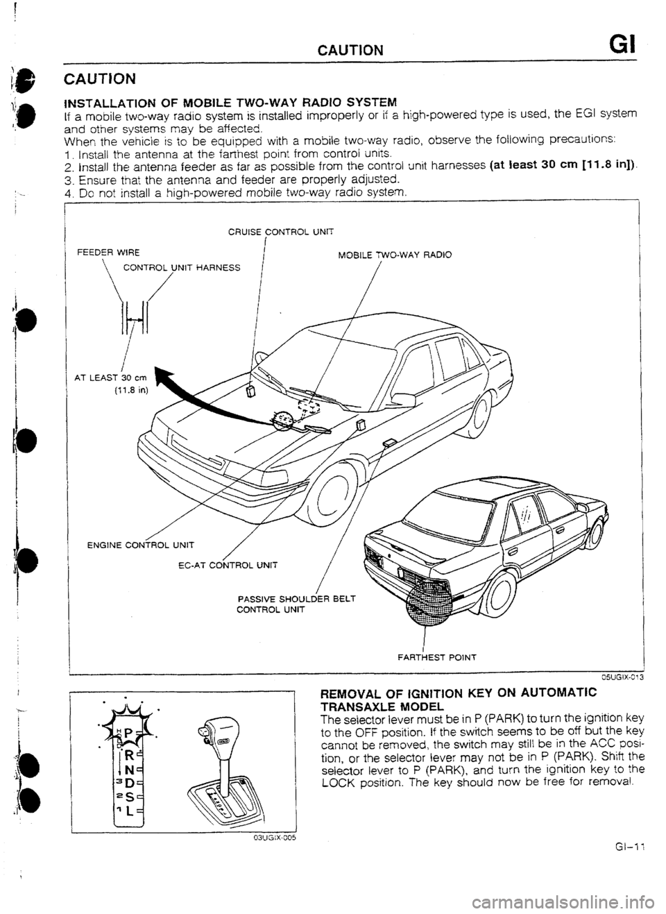
INSTALLATION OF MUBlLE TWO-WAY RADIO SYSTEM
If a mobile two-way radio system is installed improperly or if a high-powered type is used, the EGl system
and other systems may be affected.
When the vehicle is to be equipped with a mobile two-way radio, observe the fotlowing precautions:
I. Install the antenna at the farthest point from control units.
2. Install the antenna feeder as far as possible from the control unit harnesses (at Ieast 30 cm Ill.8 in]).
3. Ensure that the antenna and feeder are properly adjusted.
4. Do not install a high-powered mobile two-way radio system
r
CAUTION GI
i
CRUISE CONTROL UNIT
FEEDER WIRE
MOBILE TWO-WAY RADlO
CONTROt/UNlT HARNESS
/
AT . LEAST 30 cm
(f1.3 in)
ENGINE C0NiROL UNIT
/
FAR&T POlNT
REMOVAL OF IGNITION KEY ON AUTOMATIC
TRANSAXLE MODEL
The seiector iever must be in P (PARK) to turn the
ignition key
to the OFF position. If the switch seems to be off but the key
cannot be removed, the switch may stilt be in the ACC posi-
tion, or the selector lever may not be in P (PARK). Shitt the
selector lever to P (PARK), and turn the ignition key to the
LOCK position. The key should now be free for removal.
Page 21 of 677

A PRE-DELIVERY INSPECTION
PRE-DELIVERY INSPECTION TABLE
pieziG-
INSPECT and ADJUST, if necessary, the following Items to
specification:
D Glass, exterior bright metal and paint for damage
Cl Wheel tug nuts
9 Trre pressures
LII All weatherstrips for damage or detachment
Z Operation of bonnet release and lock
D Operation of trunk lid, hatch and fuel lid opener
(it equipped)
3 Door operation and alignment
5 Headlight aiming
INSTALL the following parts:
D Wheel caps or rings (if equipped)
D Outside mirror(s)
[ UNDER BONNET-ENGINE OFF )
INSPECT and ADJUST, if necessary, the foIlowIng items to
specification:
Cl Fuel, coolant and hydraulrc lines, fittings, connections and
components for leaks
Cl Engine oil level
0 Power steering fluid level (if equipped)
D Brake master cylinder fluid levels
0 Clutch master cylinder fluid levels (if equipped) q
Windshield washer reservoir fluid level
D Radiator coolant level and specific gravity
Ll Tightness of water hose clamps
I3 Tightness of battery terminals, electrolyte level and specific
gravity
c) Manual transaxle oit level
D Drive belt(s) tension
C; Carburetor linkage (choke control, wide open throttle posi-
tion, etc.) (carburetor model only)
D Accelerator cable and linkage for free movement
D Headlight cleaner and fluid level (if equipped)
BLEED air from fuel line (diesel engine only)
CLEAN the spark plugs (except for diesef engine)
piicis-1
INSTALL the foflowing parts:
C Rubber stopper for inside rear view mirror (if equipped)
c! Fuse for accessories
CHECK the operation of the following items:
Cl Seat controls (sliding and redining) and head rest
ci Seat belts and warnrng system
Z! Ignition swrtch and steering lock
III Power window {if equipped)
0 Door locks including child proof door locks
0 Inhibitor switch
(ATX only)
Z All lights including warning and indicator lights
0 Ignrtron key reminder buyer (if equipped) Cl Horn, wipers and washers (front and rear, if equipped)
D Antenna (if equipped} q
Cigarette lighter and clock (if equipped)
I2 Remote controt outside mirror
(if equipped) q
Heater, defogger and air conditioner at various mode selec-
tions (if equipped)
c3 Sunroof (if equipped)
CHECK
the fotiowing items: q
Presence of spare fuse
c3 Upholstery and interior finish
CHECK and ADJUST, if necessary, the following items:
Cl Operation and fit of windows
D Pedal height and free ptay of brake and clutch pedal
Cl Parking brake
i UNDER BONNET-ENGtNE RUNNING AT ]
1 OPERATtNG TEMPERATURE
CHECK the following items:
Cl Operation of idle-up system for air conditioner or power steer-
ing (if equipped)
13 Automatic transaxle fluid level
D Initial ignition timing
(except disel engine) q
Idle speed
El Operation of throttle position sensor (EGI engine)
13 Operation of cold start device and glow plug warning light
(diesel engine only)
D Operation of dash pot [EGI engine)
t
ON HOtST 1
CHECK the following items:
U Underside fuel, coolant and hydraulic lines, fittings, connec-
tions and components for leaks q
Tires for cuts or bruises
Cl Steering linkage, suspension, exhaust system and all under-
side hardware for
looseness or damage
1 ROAD TEST 1
CHECK the foliowing items:
II Brake operation
D Clutch operation
0 Steering control
c3 Operation of meters and gauges
0 Squeaks, rattles or unusual noises q
Engine general performance
c3 Emergency Iocking retractors
rAFTER ROAD TEST 1
REMOVE the seat and floor mat protective covers
CHECK for the necessary
owner information materials, tools
and spare tire in vehicle
93EOAX-002
A-2