MAZDA 323 1989 Factory Repair Manual
Manufacturer: MAZDA, Model Year: 1989, Model line: 323, Model: MAZDA 323 1989Pages: 1164, PDF Size: 81.9 MB
Page 891 of 1164
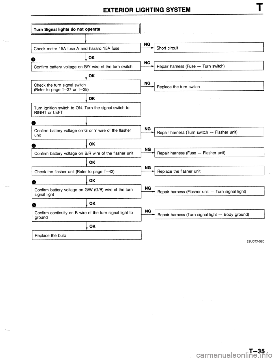
EXTERIOR LIGHTING SYSTEM
Turn Signal lights do not operate
Check meter 15A fuse A an
I
0 OK
Confirm battery voltage on BI Repair harness (Fuse - Turn switch) OK
1 ~,-
Check the turn signal switch NG
(Refer to page T-27 or T-28) Replace the turn switch
1 OK
Turn ignition switch to ON. Turn the signal switch to
RIGHT or LEFT
Confirm battery voltage on G or Y wire of the flasher
unit Repair harness (Turn switch - Flasher unit)
6) OK
Confirm battery voltage on B Repair harness (Fuse - Flasher unit)
1
1 OK
Check the flasher unit (Refe Replace the flasher unit
I
(B OK
Confirm battery voltage on G/W (G/B) wire of the turn
signal light NG _
Repair harness (Flasher unit - Turn signal light) @ OK
Confirm continuity on B wire of the turn signal light to
ground OK
Replace the bulb NG
Repair harness (Turn signal light - Body ground)
23UOTX-020
T-35
Page 892 of 1164
I
EXTERIOR LIGHTING SYSTEM
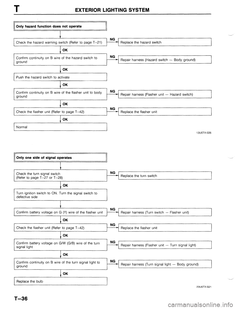
Only hazard function does not operate
Check the hazard warning Replace the hazard switch
1 I
1 OK
Confirm continuity on B wire of the hazard switch to
ground Repair harness (Hazard switch - Body ground)
OK
I I
Push the hazard switch to activate
OK -2
Confirm continuity on B wire of the flasher unit to body
ground NG
Repair harness (Flasher unit - Hazard switch)
OK
NG
Check the flasher unit (Refer
Replace the flasher unit
Normal
I
Only one side of signal operates
13UOTX-026 .,
Check the turn signal switch
(Refer to page T-27 or T-28)
I Replace the turn switch
1 OK
Turn ignition switch to ON. Turn the signal switch to
defective side
Repair harness (Turn switch - Flasher unit)
Replace the flasher unit
Confirm battery voltage on G/W (G/B) wire of the turn
signal light NG-
- Repair harness (Flasher unit - Turn signal light)
I OK
Confirm continuity on B wire of the turn signal light to
ground NG
Repair harness (Turn signal light - Body ground)
Replace the bulb
T-36
I OK
23UOTX-021
Page 893 of 1164
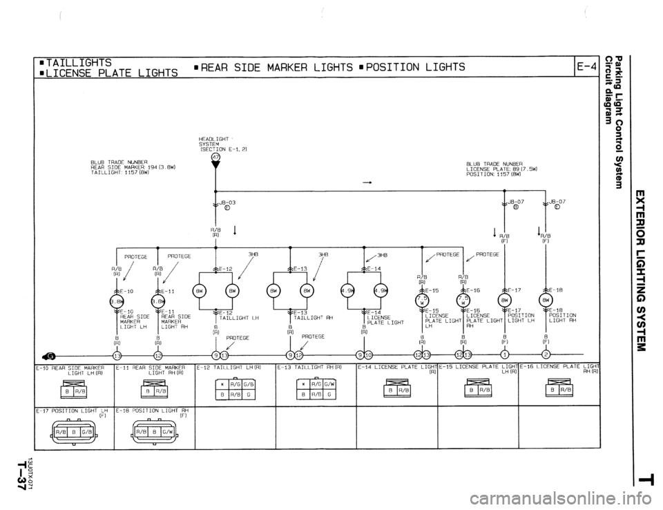
BLUB TRADE NLlNBER
REAR SIDE MARKER 194 (3.8W1 BLUE TRADE NUNBER
TAILLIGHT, 1157 (BW) LICENSE PLATE: 89 (7.5W)
POSITION: 1157 (BW)
4
0
Y
. JB-03
\B a , JE-07
y5 co , JB-07
\s 0
m TAILLIGHTS
mLICENSE PLATE LIGHTS n REAR SIDE MARKER LIGHTS mPOSITION LIGHTS
E-4
HEADLIGHT
SYSTEM
(SECTION E-I, 21
PLATE LIGHT
ri, & t:, &
Q) &
-10 REAR SIDE MARKER E-11 REAR SIDE MARKER E-12 TAILLIGHT LH (RI E-13 TAILLIGHT RH (R)
LIGHT LH (RI LIGHT RH CR1 E-14 LICENSE PLATE ,I,;,-15 LICENSE PLATE :I$$%16 LICENSE PLATE L$
-17 POSITION LIGHT (:; E-16 POSITION LIGHTEST
Page 894 of 1164
I
EXTERIOR LIGHTING SYSTEM
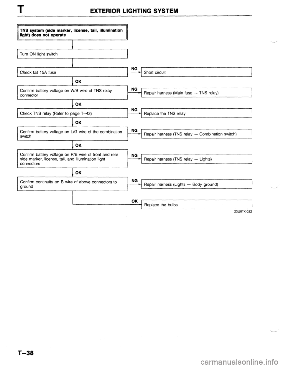
TNS system (side marker, license, tail, illumination
light) does not operate
I
Turn ON light switch
I
Check tail 15A fuse
I OK
Confirm battery voltage on W/B wire of TNS relay
connector Repair harness (Main fuse - TNS relay)
I OK
Check TNS relay (Refer to page T-42) Replace the TNS relay OK
Confirm battery voltage on L/G wire of the combination NG
switch Repair harness (TNS relay - Combination switch)
I OK
Confirm battery voltage on RIB wire of front and rear
side marker, license, tail, and illumination light
connectors Repair harness (TNS relay - Lights)
I OK
Confirm continuity on B wire of above connectors to
ground NO
- Repair harness (Lights - Body ground)
Replace the bulbs
I
23UOTX-022
T-38
Page 895 of 1164
EXTERIOR LIGHTING SYSTEM T
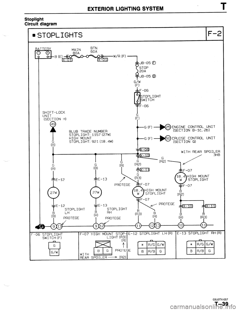
Stoplight
Circuit diaaram
GTOPLIGHTS F-2
SHIFT-LOCK
BLUB TRADE NUMBER
STOPLIGHT: 1157 (27W)
HIGH MOUNT
STOPLIGHT: 921 (18.4W) G (F) *ENGINE CONTROL UNIT
(SECTION B- lc;26)
G (F) *CRUISE CONTROL UNIT
(SECTION 01)
WITH REAR SPOILER
HIGH MOUNl-
STOPLIGHT
STOPLIGHT STOPLIGHT
-06 STOPLIGHT
SWITCH (F) F-07 HIGH MOUNT STOP-E-12 STOPLIGHT LH(R) E-13 STOPLIGHT RH(R)
LIGHT (R3)
WITH
REAR SPOILER---+ (R2)
03UOTX-057
T-39
Page 896 of 1164
I
EXTERIOR LIGHTING SYSTEM
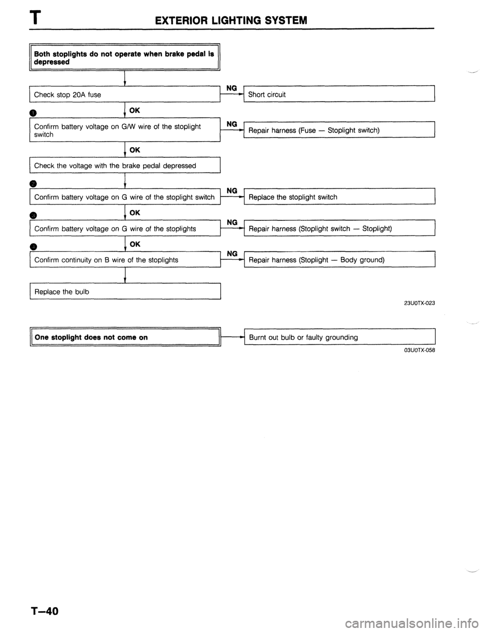
Both stoplights do not operate when brake pedal is
depressed
i
Check stop 20A fuse
I Short circuit
Confirm battery voltage on G/W wire of the stoplight
switch
I Repair harness (Fuse - Stoplight switch) OK
Check the voltage with the brake pedal depressed
I
BD
c
Confirm battery voltage on G Replace the stoplight switch
8) OK
Confirm battery voltage on G Repair harness (Stoplight switch - Stoplight)
(B
Confirm continuity on B wir Repair harness (Stoplight - Body ground)
I I I
I
Replace the bulb
I
23UOTX-023 One stoplight does not come on
Burnt out bulb or faulty grounding
03UOTX-058
T-40
Page 897 of 1164

EXTERIOR LIGHTING SYSTEM T
HEADLIGHT AND FRONT COMBINATION LIGHT
Removal / Installation
1, Remove in the order shown in the figure.
2. Install in the reverse order of removal.
b 2
13UOTX-02:
1. Screw
2. Front combination light 6. Lower grille molding
7. Fastener
Inspection . . . . . . . . . . . . . . . . . . . . . . . . . . . . . . . . ..,
3. Bolt page
T-42
8. Screw
9. Bulb
4. Fastener
5. Headlight
Inspection . . . . . . . . . . . . . . . . . . . . . . . . . . . . . . . . . . .
Aiming . . . . . . . . . . . . . . . . . . . . . . . . . . . . . . . . . . . . . . . . . page T-42
page T-30
T-41
Page 898 of 1164
EXTERIOR LIGHTING SYSTEM
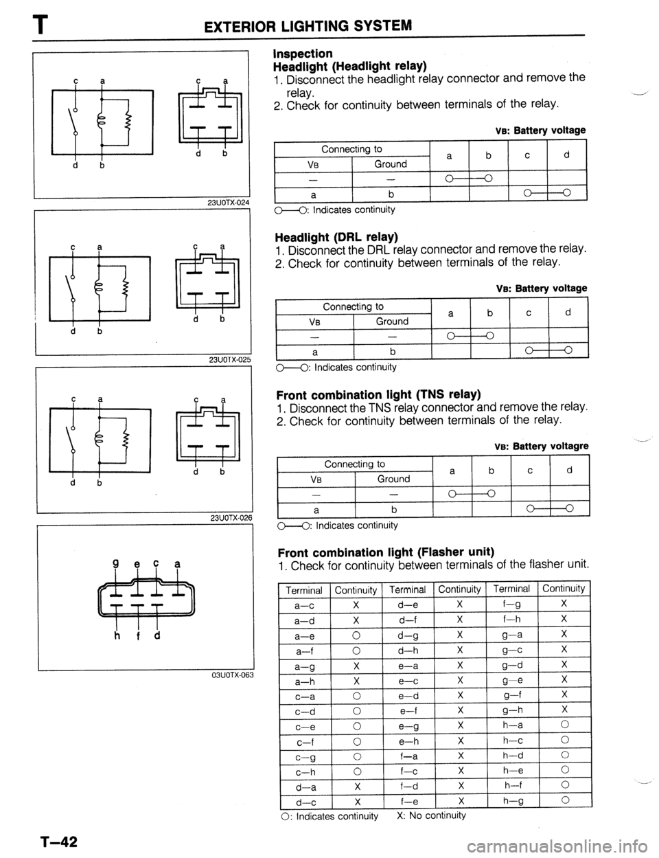
Inspection
Headlight (Headlight relay)
1. Disconnect the headlight relay connector and remove the
relay.
2. Check for continuity between terminals of the relay.
d b
23UOTX-024
C a
~
d b C
a
iYiFz3l
23UOTX-02
C a
~
d b
23UOTX-026 C
a
a
d b Qec a
I I h f d
03UOTX-063 ve: Battery voltage
Connecting to
a b c d
v0 Ground
- -
0 0
a b 0 0
o--<>: Indicates continuity
Headlight (DRL relay)
1, Disconnect the DRL relay connector and remove the relay.
2. Check for continuity between terminals of the relay.
VB: Batterv voltaae
Connecting t- n a b C d
Ve Ground
- -
C-3 I 0
r-- a b
o---O: Indicates continuity 0 1 0
Front combination light (TNS relay)
1. Disconnect the TNS relay connector and remove the relay.
2. Check for continuity between terminals of the relay.
VB: Batterv voltawe
Connecting to
a b C d VB Ground
-
0 0
I a b
O-4: Indicates continuity 0 1 0 1
Front combination light (Flasher unit)
1. Check for continuity between terminals of the flasher unit.
a-g
a-h
c-a
c-d
c-e
c-f
r--n
t------ X
e-a X
g-d X
X e-c X
g-e X
0 e-d X
g---f X
0 e-f X
P-h X
0
e-g X h-a 0
0 e-h X h-c 0
I ” Y
C-h
d-a
C
I
x 1 h-d 1 n I 0 f-a
0 f-c X h-e 0
X f-d X h-f 0
X f-e X
h-g 0
F d-
0: Indicates continuity X: No continuity
T-42
Page 899 of 1164
EXTERIOR LIGHTING SYSTEM T
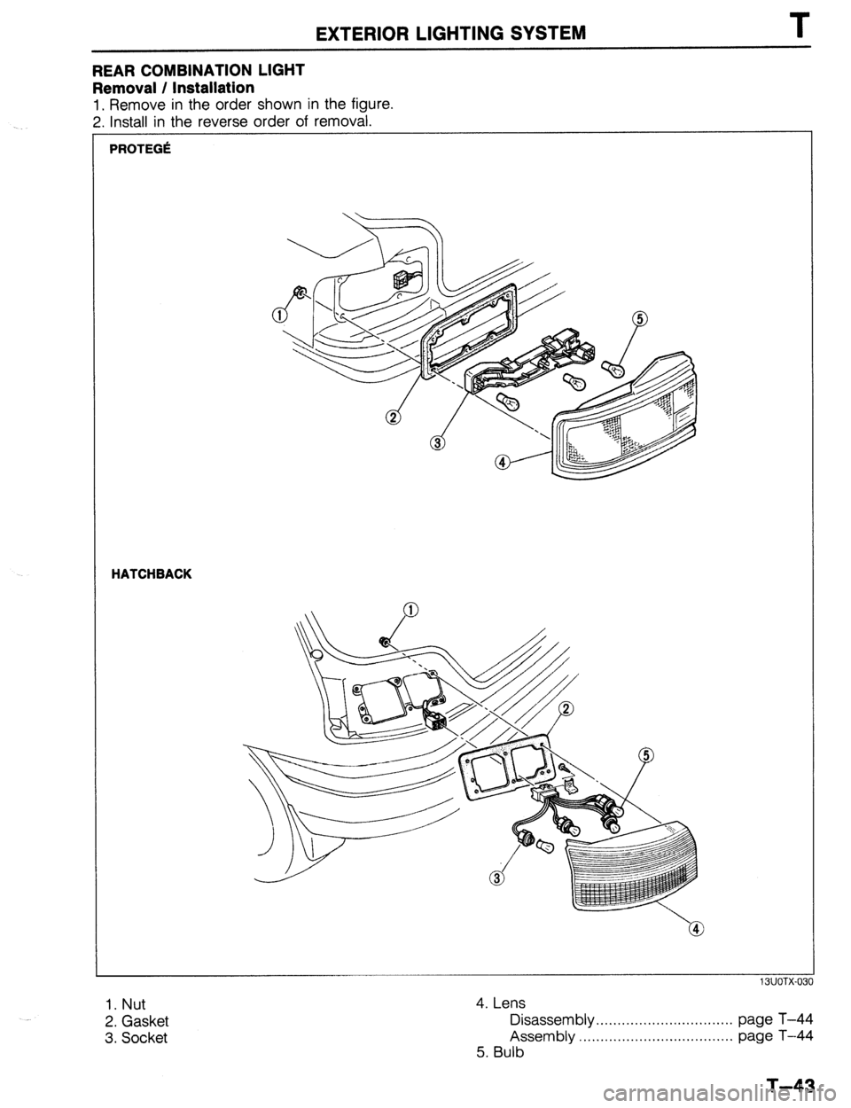
REAR COMBINATION LIGHT
Removal / Installation
1. Remove in the order shown in the figure.
2. Install in the reverse order of removal.
PROTEGlt
HATCHBACK
13UOTX-03
1. Nut
2. Gasket
3. Socket 4. Lens
Disassembly . . . . . . . . . . . . . . . . . . . . . . . . . . . . . . . . page T-44
Assembly . . . . . . . . . . , . . . , . , . . . . . . . . . . . . . . . . . . page T-44
5. Bulb
T-43
Page 900 of 1164
T EXTERIOR LIGHTING SYSTEM
r
03UOTX-066
03UOTX-06 7
03UOTX-06:
T-44
03UOTX-066
3
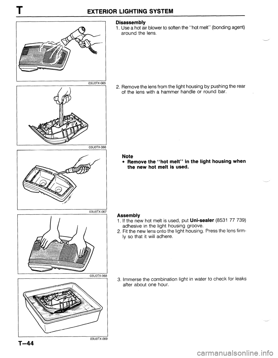
Disassembly
1, Use a hot air blower to soften the “hot melt” (bonding agent)
around the lens.
-
2. Remove the lens from the light housing by pushing the rear
of the lens with a hammer handle or round bar.
Note
l Remove the “hot melt” in the light housing when
the new hot melt is used.
Assembly
1. If the new hot melt is used, put Uni-sealer (853
.a _a 1 77 739)
adhesive In tne light housing groove.
2. Fit the new lens onto the light housing. Press the lens firm-
ly so that it will adhere.
3. Immerse the combination light in water to check for leaks
after about one hour.