heater MAZDA 323 1989 Factory Repair Manual
[x] Cancel search | Manufacturer: MAZDA, Model Year: 1989, Model line: 323, Model: MAZDA 323 1989Pages: 1164, PDF Size: 81.9 MB
Page 1 of 1164
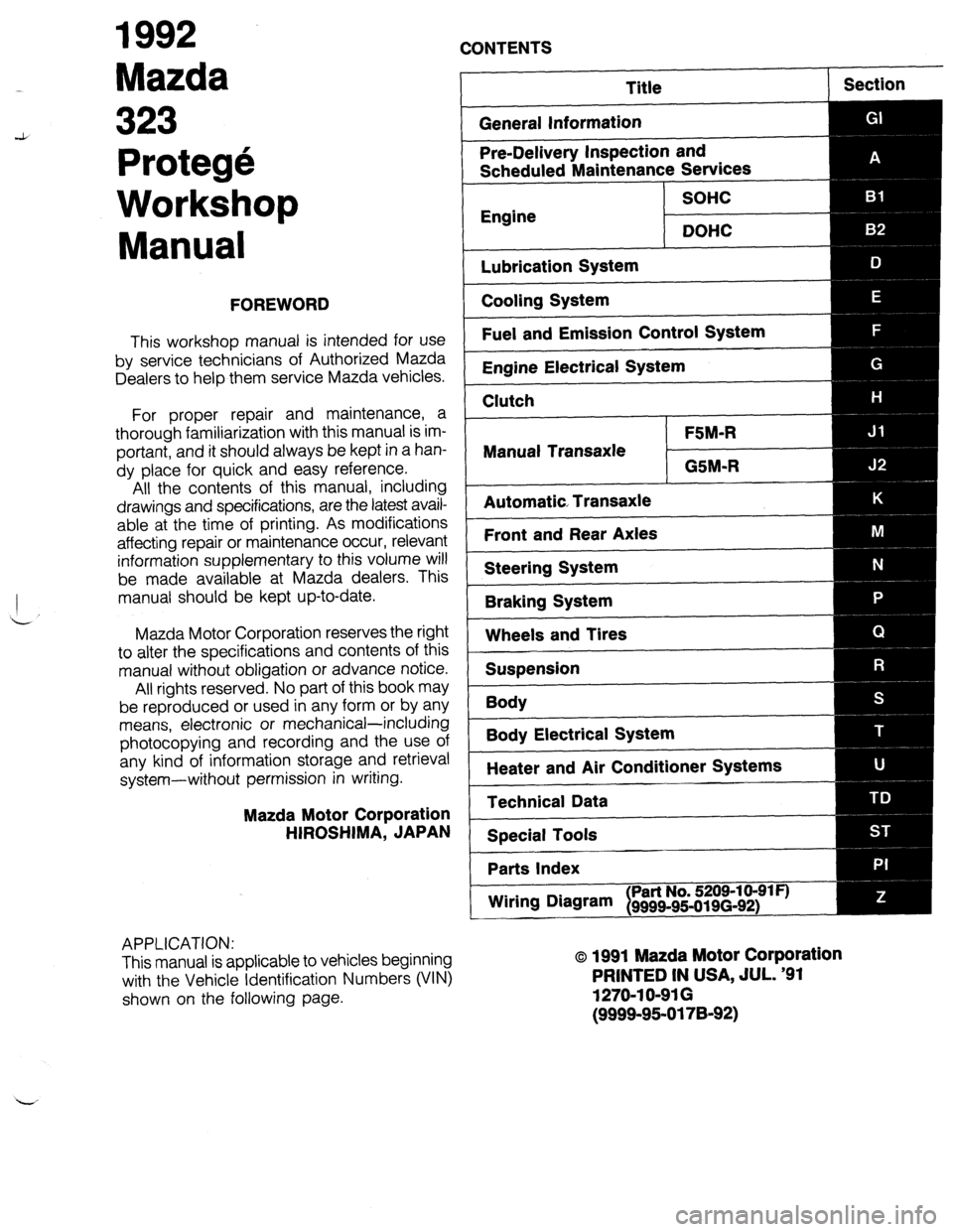
1992
Mazda
CONTENTS
Protege
Workshop
Manual
FOREWORD
This workshop manual is intended for use
by service technicians of Authorized Mazda
Dealers to help them service Mazda vehicles.
For proper repair and maintenance, a
thorough familiarization with this manual is im-
portant, and it should always be kept in a han-
dy place for quick and easy reference.
All the contents of this manual, including
drawings and specifications, are the latest avail-
able at the time of printing. As modifications
affecting repair or maintenance occur, relevant
information supplementary to this volume will
be made available at Mazda dealers. This
manual should be kept up-to-date.
Mazda Motor Corporation reserves the right
to alter the specifications and contents of this
manual without obligation or advance notice.
All rights reserved. No part of this book may
be reproduced or used in any form or by any
means, electronic or mechanical-including
photocopying and recording and the use of
any kind of information storage and retrieval
system-without permission in writing.
Mazda Motor Corporation
HIROSHIMA, JAPAN
APPLICATION:
This manual is applicable to vehicles beginning
with the Vehicle Identification Numbers (VIN)
shown on the following page.
Title
General Information Section
Pre-Delivery Inspection and
Scheduled Maintenance Services
SOHC
Engine
DOHC
Lubrication System
Cooling System
Fuel and Emission Control System
Engine Electrical System
Clutch
FSM-R
Manual Transaxle
GSM-R
Automatic Transaxle
Front and Rear Axles
Steering System
Braking System
Wheels and Tires
Suspension
Body
--
Body Electrical System
Heater and Air Conditioner Systems
Technical Data
Special Tools
Parts Index
Wiring DNvam
I Part No. 5209-10-91 F)
9999~95-019(3-92)
o 1991 Mazda Motor Corporation
PRINTED IN USA, JUL. ‘91
1270-l O-91 G
(9999-95-0178-92)
Page 20 of 1164
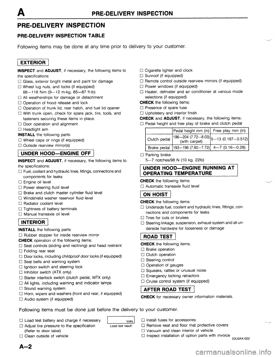
PRE-DELIVERY INSPECTION
PRE-DELIVERY INSPECTION
PRE-DELIVERY INSPECTION TABLE
Following items may be done at any time prior to delivery to your customer.
INSPECT and ADJUST, if necessary, the following items to
the specifications:
0 Glass, exterior bright metal and paint for damage
Cl Wheel lug nuts, and locks (if equipped)
88-118 N.m (9-12 m-kg, 65-87 ft-lb)
q All weatherstrips for damage or detachment
0 Operation of hood release and lock
0 Operation of trunk lid, rear hatch, and fuel lid opener
Cl With trunk open, check for spare jack, tire, tools, and
fasteners securing these items in place.
Cl Door operation and alignment
Cl Headlight aim
INSTALL the following parts:
Cl Wheel caps or rings (if equipped)
q Outside rearview mirror(s)
1 UNDER HOOD-ENGINE OFF )
INSPECT and ADJUST, if necessary, the following items to
the specifications:
0 Fuel, coolant and hydraulic lines, fittings, connections and
components for leaks
Cl Engine oil level
0 Power steering fluid level
0 Brake and clutch master cylinder fluid level
El Windshield washer reservoir fluid level
Cl Radiator coolant level
Cl Tightness of battery terminals
Cl Manual transaxle oil level
riizmiq
INSTALL the following parts:
Cl Rubber stopper for inside rearview mirror
CHECK operation of the following items:
0 Seat controls (sliding and reclining) and head restraint
Cl Folding rear seat
0 Door locks, including childproof door locks (if equipped)
Seat belts and warning system
Cl Ignition switch and steering lock
0 Inhibitor switch (ATX only)
U Starter interlock switch (clutch pedal, MTX only)
Cl All lights, including warning and indicator lamps
Cl Sound warning system
Cl Horn, wipers and washers (front and rear, if equipped)
0 Audio system (if equipped) 0 Cigarette lighter and clock
0 Sunroof (if equipped)
II Remote control outside rearview mirrors (if equipped)
Cl Power windows (if equipped)
q Heater, defroster and air conditioner at various mode
selections (if equipped)
CHECK the following items:
Cl Presence of spare fuse
0 Upholstery and interior finish
CHECK and ADJUST, if necessary, the following items:
0 Pedal height and free play of brake and clutch pedal
Pedal height mm (in) Free play mm (in)
0 Parking brake
5-7 notches/98 N (10 kg, 22lb)
UNDER HOOD-ENGINE RUNNING AT
OPERATING TEMPERATURE
CHECK the following items:
q Automatic transaxle fluid level
[I
CHECK the following items:
Cl Underside fuel, coolant and hydraulic lines, fittings, con-
nections and components for leaks
0 Tires for cuts or bruises
0 Steering linkage, suspension, exhaust system and all un-
derside hardware for looseness or damage
[I
CHECK the following items:
0 Brake operation
0 Clutch operation
Cl Steering control
Cl Operation of gauges
q Squeaks, rattles or unusual noise
Cl Emergency locking retractors
0 Cruise control system (if equipped)
1 AFTER ROAD TEST (
CHECK for necessary owner information materials.
Following items must be done just before the delivery to your customer.
q Load test battery and charge if necessary
1 Volts 1 0 Install fuses for accessories
i.. _
0 Adjust tire pressure to the specification
Load test result cl Remove seat and floor mat protective covers
(Refer to door label) 0 Vacuum and clean interior of vehicle
0 Clean outside of vehicle q Inspect installation of option parts with invoice
23UOAX-002
A-2
Page 47 of 1164
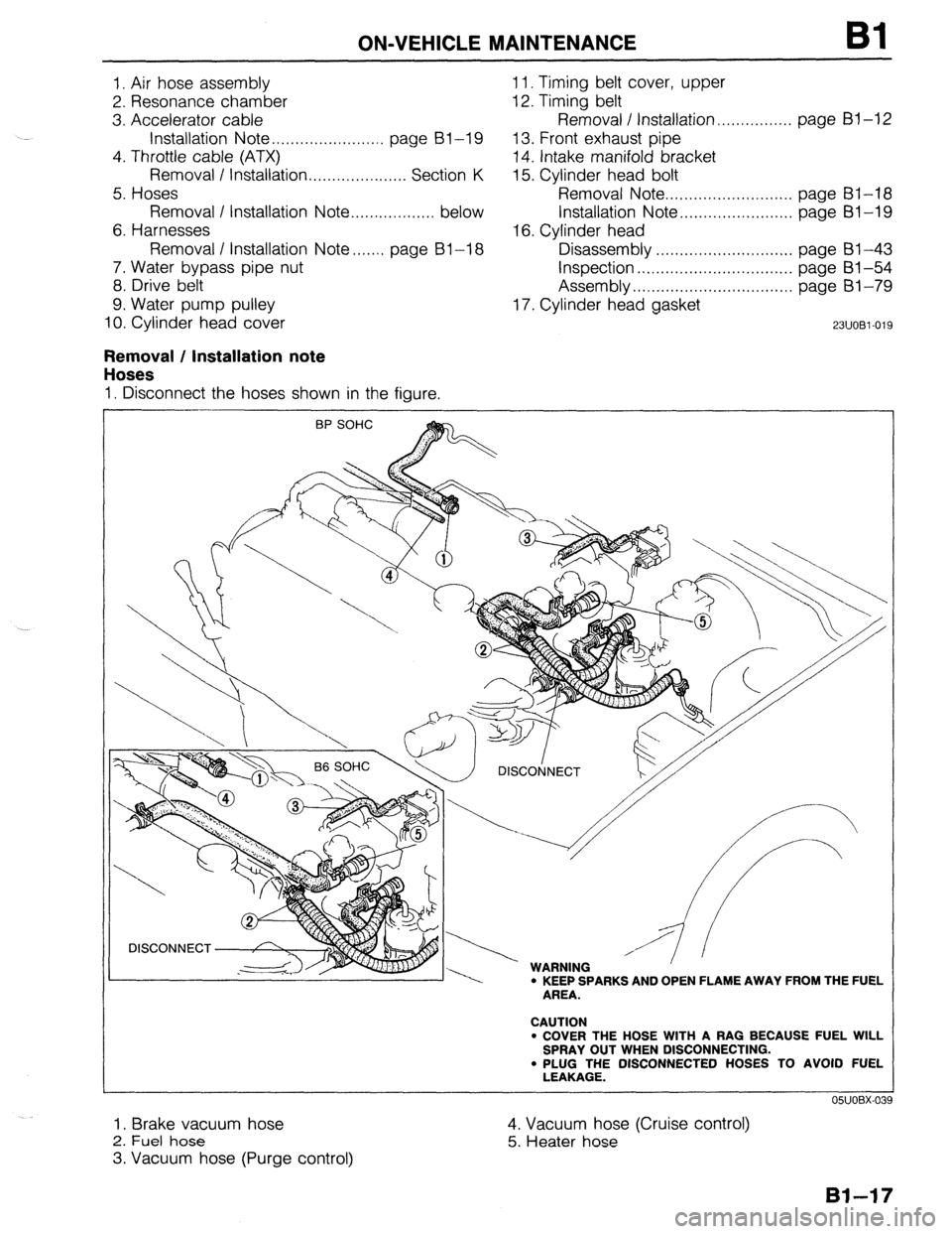
ON-VEHICLE MAINTENANCE Bl
I. Air hose assembly 1 I. Timing belt cover, upper
2. Resonance chamber 12. Timing belt
3. Accelerator cable Removal / Installation.. . . . . . . . . . . . . . . page Bl-12
Installation Note . . . . . . . . . . . . . . . . . . . . . . . . page BI-I9 13. Front exhaust pipe
4. Throttle cable (ATX)
14. Intake manifold bracket
Removal / Installation . . . . . . . . . . . . . . . . . . . . . Section K 15. Cylinder head bolt
5. Hoses Removal Note . . . . . . . . . . . . . . . . . . . . . . . . . . . page BI-18
Removal I Installation Note ..,............... below Installation Note . . . . . . . . . . . . . . . . . . . . . . . . page Bl-I9
6. Harnesses 16. Cylinder head
Removal I Installation Note....... page BI-I8 Disassembly . . . . . . . . . . . . . . . . . . . . . . . . . . . . page 61-43
7. Water bypass pipe nut
Inspection . . , . . . . . . . . . . . . . . . . . . . . . . . . . ., . . page BI -54
8. Drive belt Assembly . . . . . . . . . . . . . . . . . . . . . . . . . . . . . . . . . . page BI-79
9. Water pump pulley 17. Cylinder head gasket
10. Cylinder head cover
23UOBl-019
Removal / Installation note
Hoses
I. Disconnect the hoses shown in the figure.
\ / DlSCOtjNECT
, w I.,,, -----. WARNING ’ ’ ’ l KEEP SPARKS AND OPEN FLAME AWAY FROM THE FUEL
AREA.
CAUTION
l COVER THE HOSE WITH A RAG BECAUSE FUEL WILL
SPRAY OUT WHEN DISCONNECTING.
. PLUG THE DISCONNECTED HOSES TO AVOID FUEL
LEAKAGE.
I. Brake vacuum hose
2. Fuel hose
3. Vacuum hose (Purge control) 4. Vacuum hose (Cruise control)
5. Heater hose
Page 60 of 1164
Bl REMOVAL
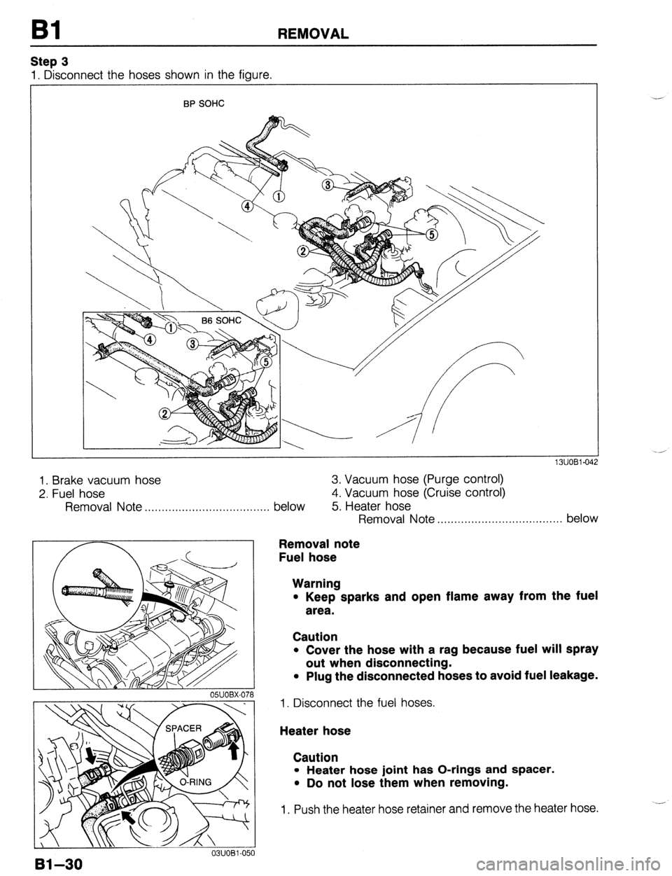
Step 3
1. Disconnect the hoses shown in the figure.
BP SOHC
1. Brake vacuum hose
2. Fuel hose
Removal
Note . . . . . . . . . . . . . . . . . . . . . . . . . . . . . . . . . . .
Bl-30
05UOBX-078
03UOBi -050
below 3. Vacuum hose (Purge control)
4. Vacuum hose (Cruise control)
5. Heater hose
Removal Note ..,,,................................ below
Removal note
Fuel hose
Warning
l Keep sparks and open flame away from the fuel
area.
Caution
l Cover the hose with a rag because fuel will spray
out when disconnecting.
l Plug the disconnected hoses to avoid fuel leakage.
1. Disconnect the fuel hoses.
Heater hose
Caution
l Heater hose joint has O-rings and spacer.
l Do not lose them when removing.
1. Push the heater hose retainer and remove the heater hose.
Page 165 of 1164
REMOVAL
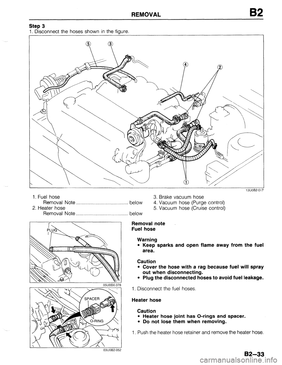
Step 3
1. Disconnect the hoses shown in the figure.
J”“DC-” I I
1. Fuel hose
3. Brake vacuum hose
Removal
Note . . . . . . . . . . . . . . . . . . . . . . . . . . . . . . . . . . . . .
below
4. Vacuum hose (Purge control)
2. Heater hose
Removal Note . . . . . . . . . . . . . , . . . . . . . . . . . .
05UOBX-078
0311082-052
. . . . .
below 5. Vacuum hose (Cruise control)
Removal note
Fuel hose
Warning
l Keep sparks and open flame away from the fuel
area.
Caution
l Cover the hose with a rag because fuel will spray
out when disconnecting.
l Plug the disconnected hoses to avoid fuel leakage.
1. Disconnect the fuel hoses.
Heater hose
Caution
l Heater hose joint has O-rings and spacer.
l Do not lose them when removing.
1. Push the heater hose retainer and remove the heater hose.
82-33
Page 231 of 1164
INSTALLATION
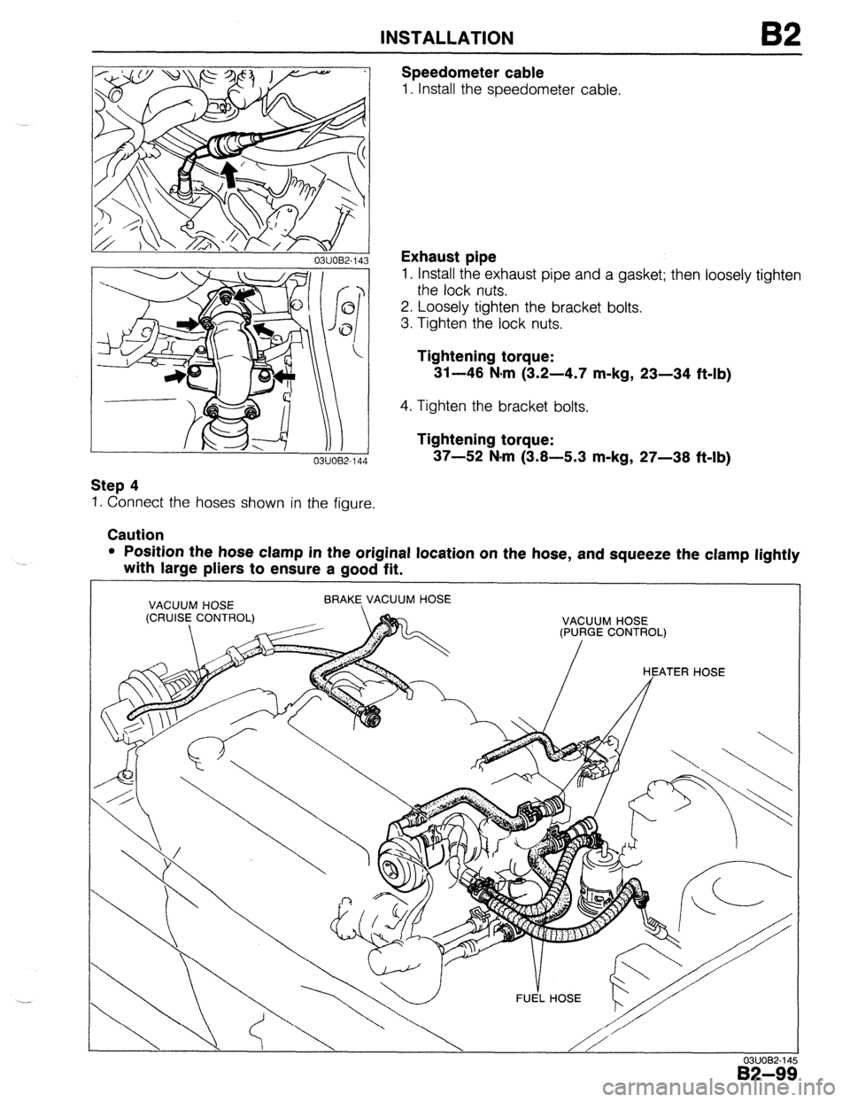
Step 4
I. Connect the hoses shown in the figure.
Caution Speedometer cable
1. Install the speedometer cable.
Exhaust pipe
1. Install the exhaust pipe and a gasket; then loosely tighten
the lock nuts.
2. Loosely tighten the bracket bolts.
3. Tighten the lock nuts.
Tightening torque:
31-46 N-m (3.2-4.7 m-kg, 23-34 ft-lb)
4. Tighten the bracket bolts.
Tightening torque:
37-52 N.m (3.8-5.3 m-kg, 27-38 ft-lb)
l Position the hose clamp in the original location on the hose, and squeeze the clamp lightly
with large pliers to ensure a good fit.
VACUUM HOSE
(CRUISE CONTROL) BRAKE, VACUUM HOSE 1 VACUUM HOSE
(PURGE CONTROL)
HEATER HOSE
FUE’L HOSE
03UOB2-14
B2-9:
Page 251 of 1164
E
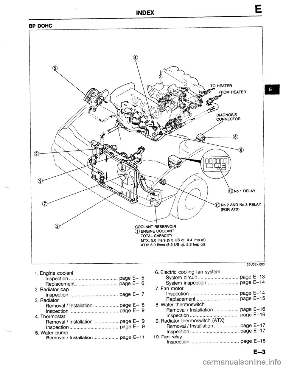
BP DOHC
-a TO HEATER
&$ No.1 RELAY
COOLANT ~~ESERVOI~~
@ ENGINE COOLANT
TOTAL CAPACITY
MTX: 5.0
liters (5.3 US qt, 4.4 Imp qt)
ATX: 6.0 liters (6.3 US qt, 5.3 Imp qt)
23UOEX-00
1. Engine coolant
6. Electric cooling fan system
Inspection ...................................
page E- 5 System circuit
.............................
page E-l 3
Replacement ...............................
page E-
6 System inspection
....................... page E-14
2. Radiator cap
7. Fan motor
Inspection ................................... page E- 7
Inspection ...................................
page E-14
3. Radiator
Replacement..
............................. page E-i 5
Removal / Installation..
................
page E-
8 8. Water thermoswitch
Inspection
.................. ................................... page E- 9 Removal / Installation
page E-16
4. Thermostat
Inspection ...................................
page E-l 6
Removal I Installation
.................. page E- 9 9. Radiator thermoswitch (ATX)
Inspection
.................. ...................................
page E- 9 Removal I Installation
page E-l 7
5. Water pump
Inspection
...................................
page E-l 7
Removal / Installation ..................
page E-i 1 10. Fan relay
Inspection ...................................
page E-l 8
E-3
Page 831 of 1164
DASHBOARD S
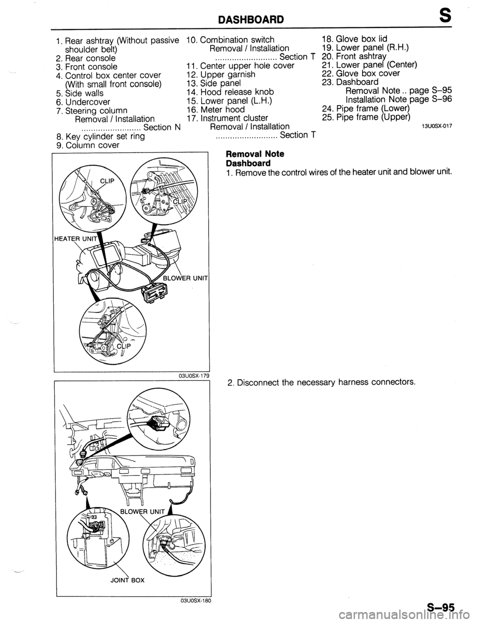
1, Rear ashtray (Without passive IO. Combination switch 18. Glove box lid
shoulder belt) Removal / Installation 19. Lower panel (R.H.)
2. Rear console ,..,,.,......,,.,.,....... Section T 20. Front ashtray
3. Front console 11. Center upper hole cover 21. Lower panel (Center)
4. Control box center cover 12. Upper garnish
22. Glove box cover
(With small front console) 13. Side panel 23. Dash board
5. Side walls 14. Hood release knob Removal Note . . page S-95
6. Undercover 15. Lower panel (L.H.) Installation Note page S-96
7. Steering column 16. Meter hood 24. Pipe frame (Lower)
Removal / Installation 17. Instrument cluster 25. Pipe frame (Upper)
. . . . . . . . ...*. . . . . ..n..... Section N Removal I Installation
1 suosx-017
8. Key cylinder set ring
9. Column cover
JOINT BOX
. . . . . . . . . . . . . . . . . . . . . . . . . . Section T
Removal Note
Dashboard
1, Remove the control wires of the heater unit and blower unit.
2. Disconnect the necessary harness connectors.
s-95
Page 832 of 1164
S DASHBOARD
03UOSX-182
03uosx-18 '3
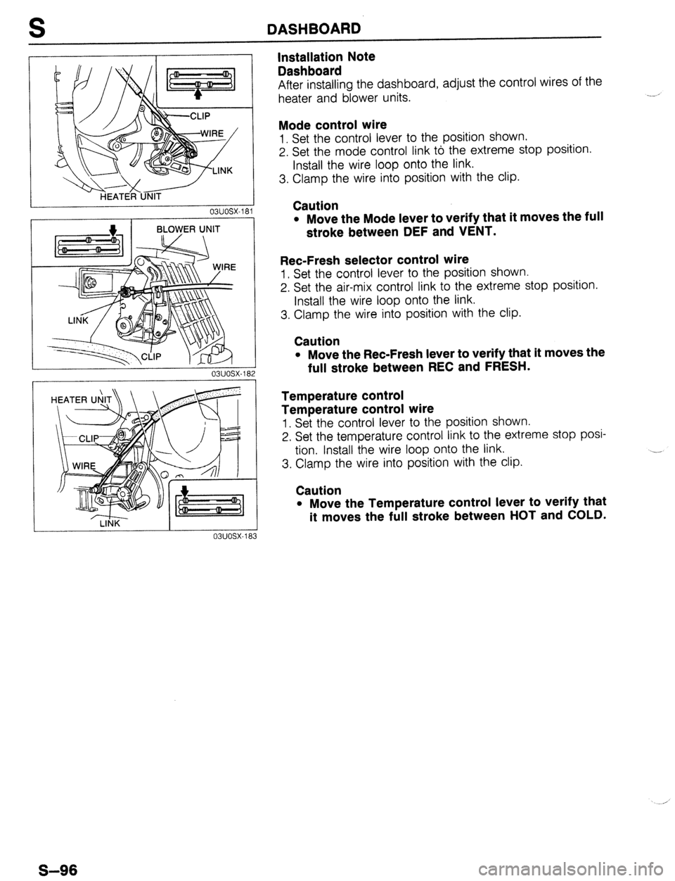
Installation Note
Dashboard
After installing the dashboard, adjust the control wires of the
heater and blower units.
Mode control wire
1. Set the control lever to the position shown.
2. Set the mode control link to the extreme stop position.
Install the wire loop onto the link.
3. Clamp the wire into position with the clip.
Caution
l Move the Mode lever to verify that it moves the full
stroke between DEF and VENT.
Ret-Fresh selector control wire
1. Set the control lever to the position shown.
2. Set the air-mix control link to the extreme stop position.
Install the wire loop onto the link.
3. Clamp the wire into position with the clip.
Caution
l Move the Ret-Fresh lever to verify that it moves the
full stroke between REC and FRESH.
Temperature control
Temperature control wire
1. Set the control lever to the position shown.
2. Set the temperature control link to the extreme stop posi-
tion. Install the wire loop onto the link.
3. Clamp the wire into position with the clip.
Caution
l Move the Temperature control lever to verify that
it moves the full stroke between HOT and COLD.
S-96
Page 866 of 1164
T
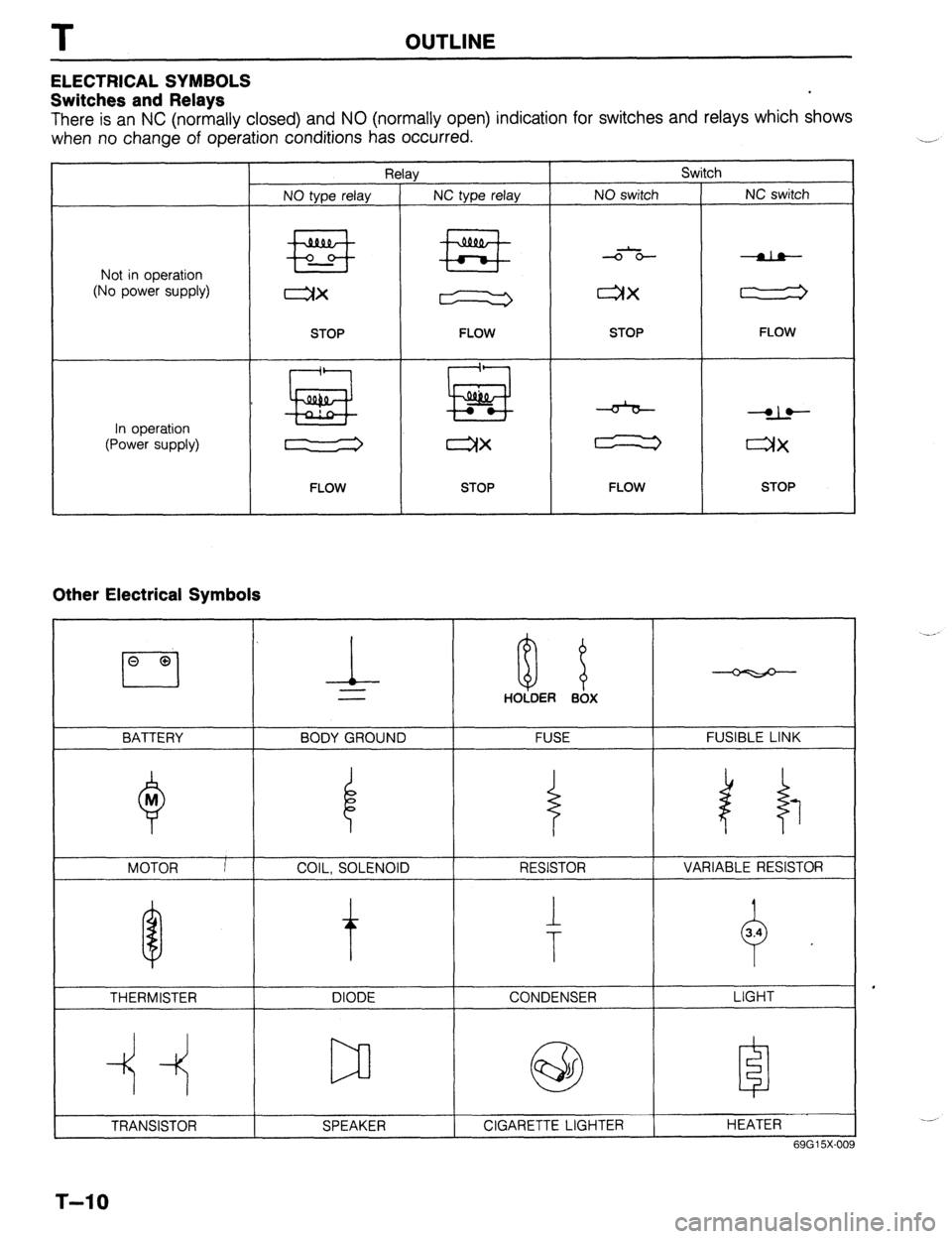
ELECTRICAL SYMBOLS
Switches and Relays OUTLINE
There is an NC (normally closed) and NO (normally open) indication for switches and relays which shows
when no change of operation conditions has occurred.
Relay Switch
NO type relay NC type relay NO switch NC switch
Not in operation
(No power supply) +E+ #Fig -o-- -da--
ax ax
STOP
FLOW STOP FLOW
In operation
(Power supply) * !jiij! kiig 6 dLe
cw r”X
FLOW STOP FLOW STOP
Other Electrical Symbols
BATTERY
THERMISTER DIODE CONDENSER
Q
M
MOTOR I
T-10
l-
BODY GROUND
COIL, SOLENOID i
0 8 HOLDER BOX
FUSE
RESISTOR
1
T
FUSIBLE LINK
1 i 1
VARIABLE RESISTOR
LIGHT
HEATER
69G15X-O(