ECU MAZDA 323 1992 Suplement Owner's Guide
[x] Cancel search | Manufacturer: MAZDA, Model Year: 1992, Model line: 323, Model: MAZDA 323 1992Pages: 279, PDF Size: 24.15 MB
Page 80 of 279

,,1
CONTROL SYSTEM F3 ‘1
Va: Battew voltage
Incorrect voltage Possible cause
Always OV
l ROOM IOA fuse burned l Open circuit In wiring from ROOM 10A fuse to ECU termina! 1A
Always OV
l Main relay malfunction l Open or short circuit in wiring from main relay to ECU terminal IB
Always OV (starter turns)
l Open or short circuit in wiring from ignition switch to ECU terminal IC
Always OV
Always VB
l Maln relay (FUEL INJ relay) malfunction l Open circuit in wiring from main relay to diagnosis connector terminal +B l Open or short circuit in wiring from diagnosis connector terminal MEN to
ECU terminal 1 D
l Poor connection at ECU connector l ECU malfunction
Always approx. 5V . ECU malfunction
Always below
2.5v
Always Ve -
-
No display on Self- * Main relay (FUEL INJ relay) malfunction
Diagnosis Checker
l Open circuit in wiring from main relay to diagnosis connector terminal + B
“88” displayed and
l Open or short clrcurt in wiring from diagnosis connector terminal FEN to
buzzer sounds con- ECU terminal tF
ti nuousl y
l Poor connection at ECU connector l ECU malfunction
Always QV
l Short circuit in wiring from igniter to ECU terminal 16
Always OV or VB
l Refer to Code No.42 Troubleshooting
(Refer to 323 4-Wheel Drtve Workshop Manual (12?9-IO-89L))
Always VB
Always OV
Always below
2.5V
Atways Ve I ’
l Fuel pump resistor/relay malfunction
l Open or short circurt in wiring from ECU terminal II to fuel pump resis-
tor/relay
A/C does not operate
l A/C reiay malfunction l Open circuit in wiring from ignition switch to A/C relay l Open circuit in wiring from A/C relay to ECU terminal 1J
A/C switch
OFF but l Short circuit in wiring from AIC relay to ECU terminal 1 J
A/C operates . ECU malfunction
l Poor connection at ECU connector l ECU malfunction
Always below 1 .OV a Short circuit in wiring from diagnosis connector terminal TEN to ECU termi-
nal 1K
Always Vs
l Open circuit In wiring from diagnosis connector terminal TEN to ECU terml-
nal IK
-
-
l Open circuit in winrig from diagnosis connector terminal GND to ground’
-
I -
.
. .
-. F3-47
Page 82 of 279

-. _.. . . . . . _ - ._.
-w
CONTROL SYSTEM F3
I .
-.
Ve: Battery voltaae I
Incorrect voltage
Atwafi below 1 .OV
Always VB
Always VS (foglight switch OK)
Always below 1 .OV
Always below 1 .OV
Always Vs
Always
below 23 (blower fan OK)
Always VB (blower fan OK)
Always below 1 .OV
(electric cooling fan OK) -
1-
Possible cause
l Throttle sensor mrsadjustment l Short circuit in wtrrng from throttle sensor to ECU terminal 1 N l ECU malfunction
l Throttle sensor mrsadjustment l Open circuit in wiring from throttle sensor to ECU terminal fN l Open circuit in mnng from throttle sensor to ECU terminal 20
l Foglight relay malfunctron
l Foglrght relay malfunction
l P/S pressure switch maltunctron l Short crrcurt In wrrlng from P/S pressure switch to ECU terminal 1 P l ECU malfunction
l P/S pressure switch malfunction l Open circuit in wlnng from P/S pressure switch to ECU terminal 7 P l Open circuit in wiring from P/S pressure switch to ground
l A/C switch malfunctron l Short circuit tn wiring from A/C switch to ECU terminal 1Q l Poor connection at ECU connector l ECU malfunction
l #C swatch malfunction l Open circuit in wiring from A/C switch to ECU terminal 1Q l Open circuit in wiring from A/C switch to blower control switch
l Open or short circuit in wiring from fan relay to ECU terminal 1R l ECU matfunction
Always below 1 .OV (blower fan OK}
Always Vs (btower fan OK)
Always betow illumination lamp
1 .ov ON when rear
window defroster
switch ON
Illumination lamp
never ON
Atways below 1 .OV (headttghts OK)
l Short circuit in wrrtng from blower control switch to ECU terminal IS l Poor connection at ECU connector l ECU m&function
l Open crrcuit in wrrrng from blower control switch to ECU terminal 1s
l Open or short crrcuit In wiring from rear window defroster switch to ECU
terminal t T
l Open circuit in wiring from ignitron switch to rear window defroster switch l Rear window defroster switch malfunction
l Open or short circuit in wiring from headlight relay to ECU terminal 1 U
Always below 1 .OV
l Neutral switch malfunction l Clutch switch malfunction l Short circuit in wiring from ECU terminal IV to neutral or clutch switch
Always VB
l Neutral switch malfunction l Clutch switch malfunction l Open circuit in wiring from ECU terminal 1V to neutral or clutch swdch l Poor connection at ECU connector
13FOl=3-36 .
F3-49
.:i
Page 84 of 279

CONTROL SYSTEM F3
VS: Battery voltage
Incorrect voltage Possible cause
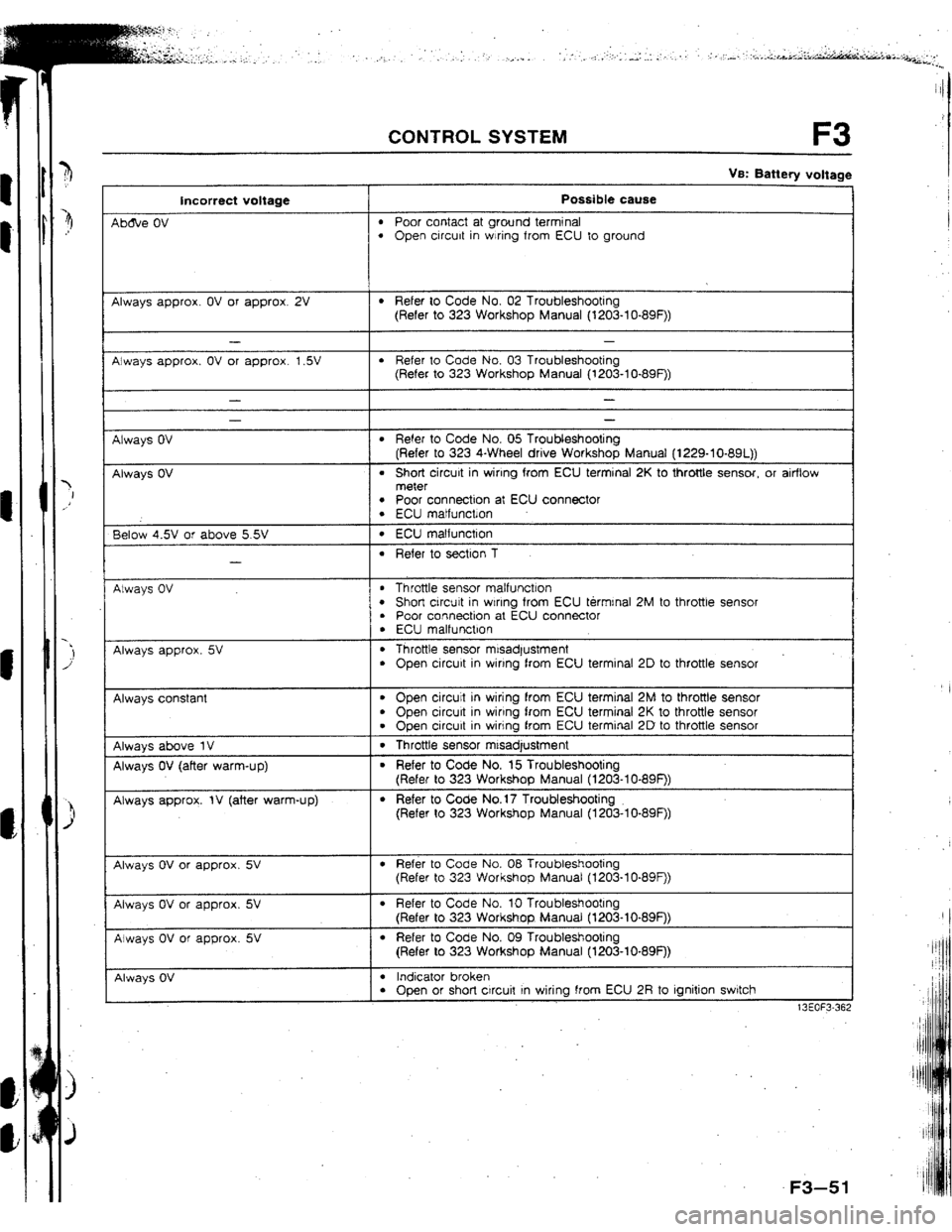
Ab&e OV
l Poor contact at ground terminal l Open circuit in wiring from ECU to ground
Always approx. OV or approx. 2V
l Refer to Code No. 02 Troubleshooting
(Refer to 323 Workshop Manual (l203-lo-89F))
Always approx. OV or approx. 1.5V
l Refer to Code No, 03 Troubleshooting
(Refer to 323 Workshop Manual (1203-lo-89F))
Always OV
Always OV
- -
l Refer to Code No. 05 Troubleshooting
(Refer to 323 4-Wheel drive Workshop Manual (1229-10-891))
l Short circuit in wiring from ECU terminal 2K to throttle sensor, or airflow
meter
l Poor connection at ECU connector l ECU matfunctlon
Below 4.5V or above 5.5V
-
l ECU matfunction
l Refer to section 1
Always OV
l Throttle sensor malfunction l Short circuit in wlnng from ECU termrnal 2M to throttle sensot l Poor connection at ECU connector
. ECU malfunction
Always approx. 5V . Throttle sensor misadjustment
l Open circuit in wiring from ECU terminal 2D to throttle sensor
Always constant
l Open circuit in wiring from ECU terminal 2M to throttle sensor
. Open circurt in wiring from ECU terminal 2K to throttle sensor
l Open circuit in wiring from ECU terminal 2D to throttle sensor
Always above 1V 1 . Throttle sensor mtsadjustment
Always OV (after warm-up)
Always approx. IV (after warm-up)
l Refer to Code No. 15 Troubleshooting
(Refer to 323 Workshop Manual (1203-I O-89F))
l Refer to Code No.17 Troubleshooting
(Refer to 323 Workshop Manual (1203-lo-89F))
Always OV or approx. 5V
l Refer to Code No. 08 Troubleshooting
(Refer to 323 Workshop Manual (t203-lo-89F))
Always OV or approx. 5V
Always OV or approx. 5V
l Refer to Code No. 10 Troubleshooting
(Refer to 323 Workshop Manual (l203-lo-89F))
l Refer to Code No. 09 Troubleshooting
(Refer to 323 Workshop Manual (1203-10.89F))
Always OV
I
l Indicator broken l Open or short circuit In wiring from ECU 2R to ignition switch
13EOF3-36;
F3
Page 86 of 279

VB: Battery voltage
Incorrect voltage Possible cause
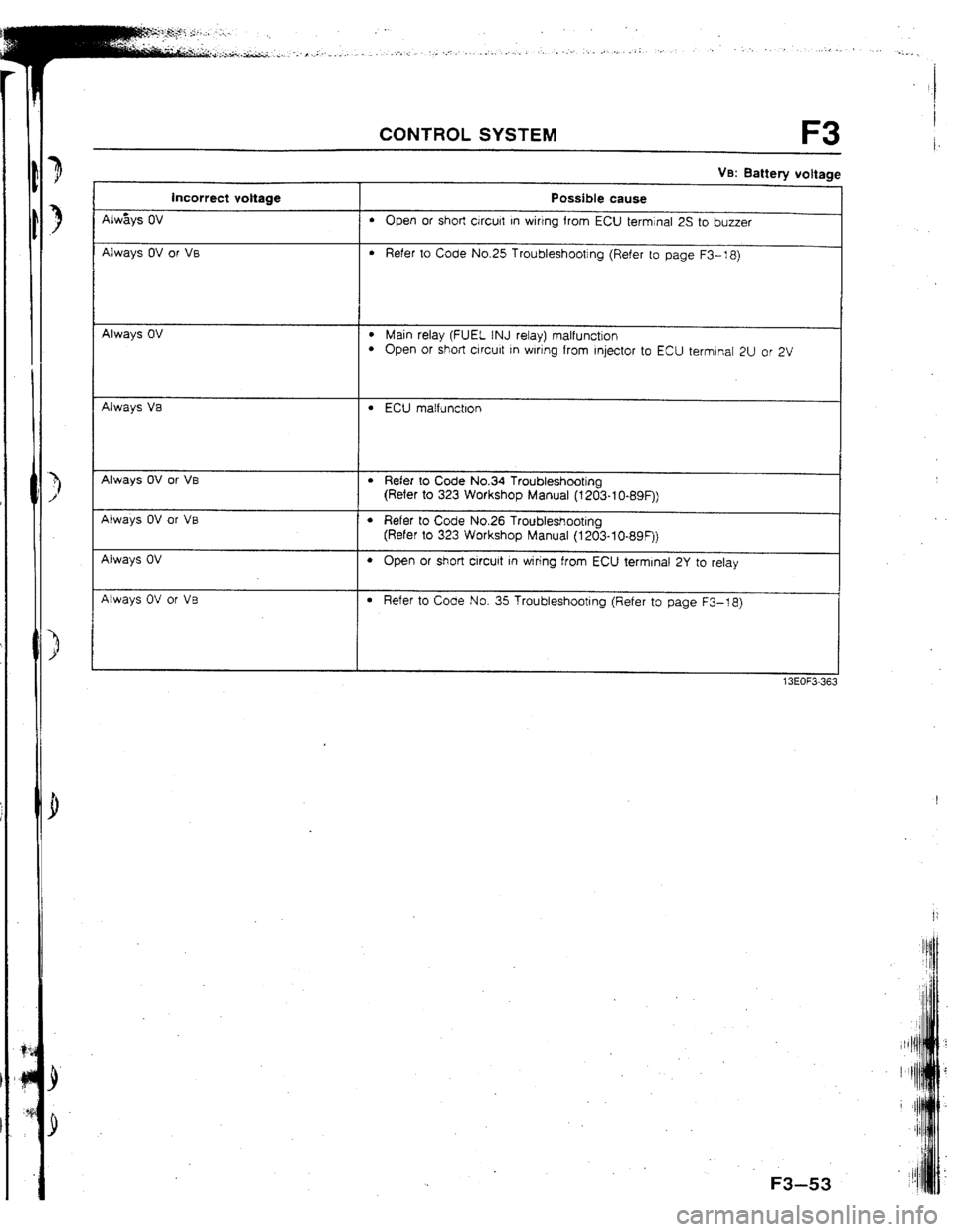
Always OV
l Open or short &curt in wirtng from ECU terminal 25 to buzzer
Always OV or VB
l Refer to Code No.25 Troubleshooting (Refer to page F3-18)
-
Always OV l Main relay (FUEL INJ relay) malfunction l Open or short crrcult rn wlnng from Injector to ECU termtnal 2U or 2V
Always Va
l ECU matfunctlon
Always OV or VB
Always OV or VB
Always OV
Atways OV or VB
l Refer to Code No.34 Troubleshooting
(Refer to 323 Workshop Manual (1203-t O-89F))
l Refer to Code No.26 Troubleshooting
(Refer to 323 Workshop Manual (1203-lO-89F))
l Open or short circuit in wiring from ECU terminal 2Y to relay
l Refer to Code No. 35 Troubleshooting (Refer to page F3-18)
F3-53
Page 99 of 279

FRONT AXLE M
13EOMX308
13EOMX-310
1
13EOMX-311
Removal note
Locknut
Caution
l Do not damage the drive shaft.
l Do not reuse the locknut.
1.
Raise the staked portion of the locknut using a chisel.
2. Lock the
hub by applying the brakes.
3. Remove the locknut.
Tie rod end
Caution i
l Do not damage the dust boot.
t
Losen the nut and disconnect the tie rod end bv using the
I
SST.
P
Installation note
Tie rod end
Caution
l Do not damage the dust boot.
tnstall the nut and secure it with the new cotter
Tightening torque:
43-56 N-m (4.3-5.8 kgf,m, 31-41 ft-lbf
Locknut
lnstail a new
locknut and stake it, as shown. pin.
Tightening torque: 236-318 N-m
f 24.0-32.5 kgfm, 174-235 ftelbf ]
M-7.
Page 129 of 279

CONVENTfONAt BRAKE SYSTEM
13EOPX-33C
16EOPX-7 16
1
3
J
13EOPX 331
Disassembly note
Piston
Remove the piston with the SST.
Note
l The piston is removed by turning the SST counter-
clockwise.
Piston seal
Remove the piston seal with the SST.
Needle bearing
1. Secure the catiper in a vise.
Caution
l Do not remove the needle bearing if not necessary.
l Insert a soft, protective material (such as copper
ptates) in the jaws of the vise.
2. Remove the needle bearing from the caliper with the SST.
Bleeder screw
Loosen the bleeder screw by using the SST.
Assembly note
Bleeder screw
Tighten the bleed screw by using the SST.
Tightening torque:
5.9-8.8 Narn f 60-90 kgfcm, 53.-78 in4bf )
.
c
P-1 8
Page 191 of 279

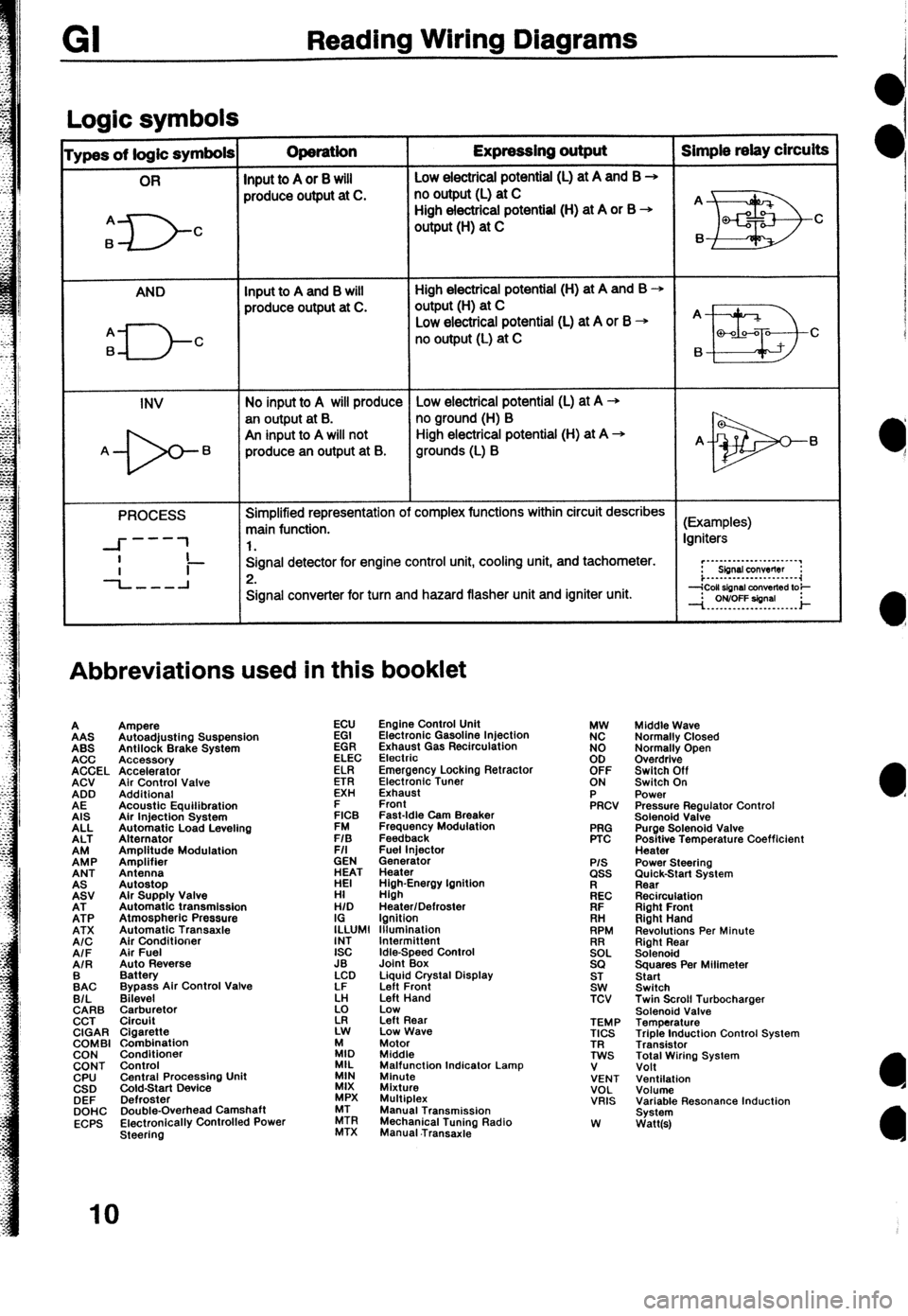
Reading Wiring Diagrams
Loaic symbols I
ypes of logic symbols Operation Expressing output Simple relay circuits
OR
Input to A or 8 will Low electricai potential (L) at A and B +
produce output at C. no output (L) at C
A
6
D- High electrical potential (H) at A or B +
C output (H) at C
AND Input to A and B will High electrical potential (H) at A and B +
produce output at C. output(H) at C
q---J-c
Low electrical potential (L) at A or B + A
no output (L) at C
B a-00-a C
6
INV No input to A will produce Low electrical potential (L) at A -+
an output at B. no ground (H) B
An input to A will not High electrical potential (H) at A +
A- 6 produce an output at B. grounds (L) B A- 6
PROCESS Simplified representation of complex functions within circuit describes
main function. (Examples)
---
--I- 1 1. Igniters
I
-L-l Signal detector for engine control unit, cooling unit, and tachometer.
Ii- 2. r”~“-‘-‘-““‘~~‘.“’
Sbnsl conwflw :
i...-..--.---......-.~~
Signal converter for turn and hazard flasher unit and igniter unit.
Abbreviations used in this booklet
A
AAS
ABS
ACC
ACCEL
ACV
ADD
AE
AIS
ALL
ALT
EP
ANT
EV
EP
ATX
A/C
AIF
AIR
:AC
B/L
CARB
CCT
CIGAR
COMBI
CON
CONT
CPU
CSD
DEF
DOHC
ECPS Ampere
Autoadjusting Suspension
Antilock Brake System
Accessory
Accelerator
Air Control Valve
Additional
Acoustic Equilibration
Air Injection System
Automatic Load Leveling
Alternator
Amplitude Modulation
Amplifier
Antenna
Autostop
Alr Supply Valve
Automatic transmission
Atmospheric Pressure
Automatic Transaxle
Air Conditioner
Air Fuel
Auto Reverse
Battery
Bypass Air Control Valve
Bilevel
$rr$:,tor
Cigarette
Combination
Conditioner
Control
Central Procassino Unit
&Id-Start Device -
Defroster
Double-Overhead Camshaft
Electronically Controlled Power
Steering ECU
EGI
EGR
ELEC
ELR
ETR
EXH
E
FICB
FM
F/S
F/I
GEN
ET
HI
H/D
I;LUMl
INT
ISC
JB
LCD
LF
k!
z Engine Control Unit
Electronic Gasoline Injection
Exhaust Gas Recirculation
Electrio
Emergency Locking Retractor
Electronic Tuner
Exhaust
Front
Fast-Idle Cam Breaker
Frequency Modulation
Feedback
Fuel lniector
Generator
Heater
High-Energy Ignition
High
Heater/Defroster
Ignition
lllumlnation
Idle-Speed Control
Joint Box
Liquid Crystal Display
Left Front
Left Hand
Low
Left Rear
Low Wave
:I, Motor
Middle
MIL
MIN Malfunction Indicator Lamp
Minute
MIX
Mixture
MPX Multiplex
ZR Manual Transmission
MTX Mechanical Tuning Radio
Manual .Transaxie PRG
PTC
P/S ass
kc
FIF
. . .
RH
RPM
!2EL
SQ
ST
SW
TCV
TEMP
TICS
TR
TWS
V
VENT
VOL
VRIS
W Middle Wave
Normally Closed
Normally Open
Overdrive
Switch Off
Switch On
Power
Pressure Regulator Control
Solenoid Valve
Purge Solenoid Valve
Positive Temperature Coefficient
Heater
Power Steering
;im&k-Start System
Recirculation
Right Front
Right Hand
Revolutions Per Minute
Right Rear
Solenoid
Squares Per Milimeter
Start
Switch
Twin Scroll Turbocharger
Solenoid Valve
Temperature
Triple Induction Control System
Transistor
Total Wiring System
Volt
Ventilation
Volume
Variable Resonance Induction
System
Watt(s)
IO
Page 192 of 279

Troubleshooting GI
Precautions to take when servicing an electrical system
l Note the following items when servicing the electrical system.
l Do not alter the wiring or electrical equipment in any way; this may damage the vehicle or cause a fire from
short-circuiting a circuit or overloading it. l
The negative (-) battery cable must be removed first and
installed last. l Do not replace with fuses exceeding specified capacity.
1OA
f5A
Zaution
o Be sure that the ignition and other switches are off
Caution
before disconnecting or connecting the battery
l Replacing a fuse with one of a larger capacity than
cables.
designated may damage components or cause a fire.
Failure to do so may damage the semiconductor
components.
0 Tape areas of the
l When mounting l Secure harnesses with provided clamps to take up slack.
harness that may rub or
components, be sure the
bump against sharp
harness is not caught or
edges to protect it from
damaged.
damage.
Zaution
B Clamp all harnesses near vibrating components
(for example, the engine) to remove slack and to
prevent contact resulting from vibration.
D Do not handle electrical components roughly or drop
them.
l Disconnect heat-
sensitive parts (for
example, relays and
ECU) when performing
maintenance (such as
welding) where
temperatures may exceed
80°C (176°F). l Make sure that the
connectors are securely
connected when
installed.
11
Page 193 of 279

Gl Troubleshooting
Handling connectors
Caution
l Be sure to grasp the connectors, not the wires, when disconnecting them.
Improperly engaged
connectors will cause
poor terminal contact. A loose terminal Will
cause poor terminal 1 Baise the rear
2.Lift the tab with a
thin piece of metal
and remove the
Lift the tab with a thin
piece of metal and
there is no looseness in connector when engaged.
the female terminal.
1 .Raise the cover.
P.Lift the terminal to
B-Make sure the
terminal is securely
mounted in the
connector when
Pull lightly on individual
wires to check that they
are secured in the 1 Raise the cover.
2.Remove A.
3.Lift the tab with a
thin piece of metal
and remove the