engine MAZDA 323 1992 Suplement Service Manual
[x] Cancel search | Manufacturer: MAZDA, Model Year: 1992, Model line: 323, Model: MAZDA 323 1992Pages: 279, PDF Size: 24.15 MB
Page 70 of 279

F3 II TURBOCHARGER CONTROL SYSTEM ‘1
1’
:j
TURBOCHARGER CONTROL
SYSTEM
TURBOCHARGER
Re’inovaf / Installation
Caution
l Be careful of the following points after turbocharger removal.
l Do not carry the turbocharger by the actuator rod or actuator hose.
l Do not drop the turbocharger.
l Set the turbocharger down with the turbine shaft horizontat.
l Cover the intake, exhaust, and oil passages to prevent dirt or other material from entering
the turbocharger.
l Use the specified new studs when installing the turbocharger.
1, Disconnect the negative battery cable.
2. Raise the vehicle and support it on safety stands.
3. Remove the undercover.
4. Orain the engine coolant.
5. Remove in the order shown in the figure, referring to Removal Note.
6. Install in the reverse order of removal, referring to Installation Note.
I-- 7.8-1 1 N-m ~80-110 kgfcm. 69-96 idbf j
3946 13.94.7, 2% 3842 13.94.3, 28-
31--46 13.2-4.7, 23-341
T, REPLACE .
12-18 1 f-2-1.8, 8.7-13 I
GASKET, REPLACE
19-26 1 t .9-2.6, 14-19 1
7.6-11 Mm t80-?lO kgfcm, 69-95 hlbfl
~-t-n 1 kgf-m, Wlbt]
13EOF3 3.31
F3-3i
Page 71 of 279

F3 TURBOCHARGERCONTROLSYSTEM
1. Radiator
2. Insulator 3. Air hose, and air pipe
4. Oxygen sensor connector
5. Front exhaust pipe
13EOF534
F3-38 6. Water hose
7. Oil pipe
8. Exhaust manifold and turbocharger
Removal Note ,.........I.....f.~.~l....... II.I.... below
Installation Note . . . . , , l.. . . . . . . , ,.. ,..*, , . . . . . . . . . below
13EOF3-339
Removal Note Exhaust
manifold and turbocharger 1. Remove the exhaust manifold and the turbocharger as an
assembly.
2. Separate the turbocharger assembly from the exhaust
manifold.
Installation Note
Exhaust manifold and turbocharger’ I I Remove .all old gaskets and
sealant. 2. Install new gaskets.
3. Supply 25 cc ( 1.5 cu in ] of oil through the oil passage
of the turbocharger.
4. Mount the turbocharger assembly to the exhaust manifold.
5. Install the turbocharger and the exhaust manifold assem-
bly to the engine and loosely tighten the nuts.
6. Install the bracket and the front exhaust pipe, and tighten
the turbocharger mounting nut%
WASTEGATE SOLENOD VALVE
Caution
l The wastegate solenoid valve must be replaced with
the turbocharger, it cannot be replaced by itself.
Inspection 1. Disconnect the connector.
2. Measure the resistance of the solenoid valve.
Resistance: 35-45 !‘l (at 20°C f68OFj) 3. M not as specified, replace the wastegate solenoid valve and
turbocharger as an assembly, if necessary.
(Refer to page F3-37.)
3. Instc
Page 74 of 279

FUEL SYSTEM F3
13EOF3.34
c I 13EOF3-364 FUEL PUMP CONNECTOR
/
!NSTALL CLAMPS
I
l nspection
1, Disconnect the resistor/relay connector.
2. Ground the fuel pump resistor relay terminal D.
3. Apply battery voltage and check for continuity as shown.
Terminal C
Continuity between A and I3
Battery voltage applied NO
ov Yes
4. Measure the resistance between terminals E and F.
Resistance : 0.38--0.42Q (at 2O*C {6S°F 1)
PRESSURE REGULATOR
Inspection
Fuel line pressure
Warning
l Before performing the following operation, release
the fuel pressure from the fuel system to reduce the
possibility of injury or fire. (Refer to page F3-21.)
1. Disconnect the negative battery terminal.
2. Connect a fuel pressure gauge between the fuel filter and
the fuel main hose. (install clamps as shown.) , .
I
3. Connect the negative battery terminal.
/t.
4, Start the engine and run it at idle.
5. Measure the fuel line pressure.
Fuel line pressure:
206-255 kPa [ 2.1-2.6 kgflcml, 30-37 psi )
6. Disconnect the upper vacuum hose from the pressure regu-
lator and measure the fuel line pressure.
Fuel line pressure:
304-392 kPa (3.1-4.0 kgf/cm2, 44-57 psi )
F3-41
Page 76 of 279

. !I11
PRESSURE REGULATOR CONTROL SYSTEM F3
13EOF3353
(PRC HIGH TEMP.)
13EOF3-35:
BAl-fERY VOLTA
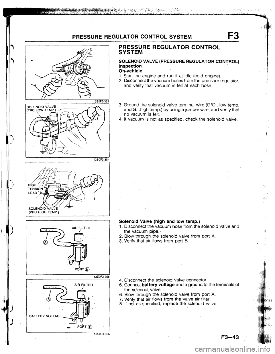
PRESSURE REGULATOR CONTROL
SYSTEM
SOLENOID VALVE (PRESSURE REGULATOR CONTROL)
Inspection
On-vehicte
1. Start the engine and run it at idle (cold engine).
2. Disconnect the vacuum hoses from the pressure regulator,
and verify that vacuum is felt at each hose.
3. Ground the solenoid valve terminal wire (G/O...low temp.
and G. ..high temp.) by using a jumper wire, and verify that
no vacuum is felt.
4. If vacuum is not as specified, check the solenoid valve.
Solenoid Valve (high and low temp.)
1, Disconnect the vacuum hose from the solenoid valve and
the vacuum pipe..
2. Blow through the solenoid valve from port A.
3. Verify that air flows from port B.
4. Disconnect the solenoid valve connector.
5. Connect battery voltage and a ground to the terminals of
the solenoid v&e.
6. Blow through the solenoid valve from port A.
7. Verify that air flows from the valve air filter.
8. If not as specified, replace the solenoid valve.
.
F3-43
Page 78 of 279

CONTROL SYSTEM F3
hT==TdI ,
USE CONNECTOR A 1
L
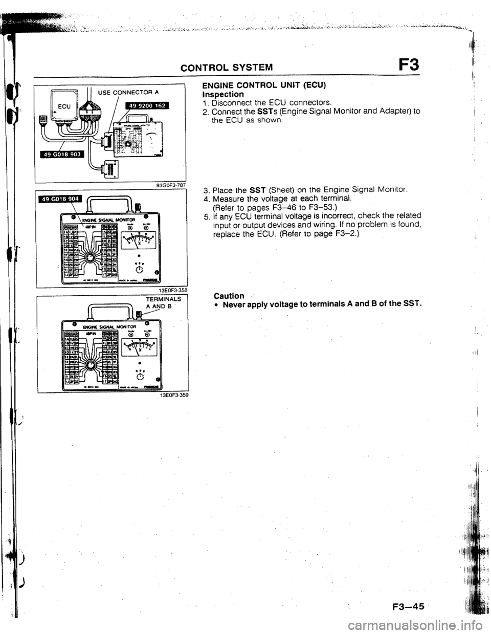
93GOF3-787 ENGINE CONTROL UNIT (ECU)
Inspection
1. Disconnect the ECU connectors.
2. Connect the SSTs {Engine Signat Monitor and Adapter) to
the ECU as shown.
3. Place the SST (Sheet) on the Engine Signal Monitor.
4. Measure the voltage at each terminal.
(Refer to pages F3-46 to F3-53.)
5. If any ECU terminal voltage is incorrect, check the related
input or output devices and wiring. If no problem is found,
replace the ECU. (Refer to page F3-2.)
t
1 13EOF3-358
r
TERMINALS
f. -I AANDB . Caution l Never apply voltage t.o terminals A and 8 of the SST.
! :OF3-359
F3-45
Page 79 of 279

F3 CONTROL SYSTEM
Terminal voltage
Reference date
Vs: Battery voltage
‘em&al Input Output Connected to Test condition Correct voltage Remark
1A - - Battery Constant VB
For backup
18 0 Main relay
Ignition switch OFF ov
(FUEL INJ relay) -
ON
V8
1C 0 lgnitlon switch While cranking Approx. 1 OV
(START) -
Ignition switch ON ov
10 0 Self-Diagnosis Test switch at SELF TEST
Wtth Self-
Checker Lamp illuminated for 3 sec. after ignition Approx. 5V
(monitor lamp) switch OFFdON Diagnosis Check-
er and System
lamp not iltuminated after 3 sec. V8 Selector
Test switch at 02 MONITOR with engine
idling Approx. 5V
Monitor lamp illuminated
Test switch at 02 MONITOR with engine
idling Vi3
Monitor lamp not illuminated
IE - - - - - -
IF
0 Self-Diagnosis Buzzer sounded for 3 sec. after ignition
Below 2SV
l With Seif-
Checker switch OFF-+ON
Diagnosis
(service code)
Buzzer not sounded after 3 set V0 ’ Checker and
Buzzer sounded Below 2.5V System Selector
l With System
Buzzer not sounded VB Selector test
switch at SELF
TEST
1G 0 igniter tgnition switch ON
ov
-
Idte
Approx. 0.2V
It-l 0
Solenoid valve Ignition switch ON
VB
(wastegate)
Idle
Approx. 2V ’ -
II
0 Fuel pump While cranking
Approx. 1 OV
resistor/relay -
Idle
8etow 1.5V
IJ 0 NC relay Ignition switch ON
VB
A/C switch UN at idle
Below 2.5V
. NC switch OFF at idle V3
-
IK 0 Diagnosis
connector
(TEN terminal) System Selector test switch at
02 MONITOR
System Selector test switch at
SELF TEST V0
-
8elow l*OV
1L - - - - - -
I
1M - - - - -
I -
lr ‘- l-7
f L.-
r
20 20 2M 2K 21 2G 2E 2c 2A IU 1S 10 10 ltvl tK II Ir; tE 1~ IA
1
22 2x 2v 2T ZR 2P 2N 2L 25 2H 2F 20 2B 1V IT 1R tP 1N IL 1J 1H IF 1~ 1~
1
J=3-46 --
4lways 4
--
AIways 4
--
Atways 1
--
Always 1
-a
Always ’
--
Always i
-e
Always I
2.5v
Always
Always (
-m
Always f
-a
Always 1
Always (
--
Always I
2.5V
Always 1
Always t
Always
--
Page 83 of 279

F3 CONTROL SYSTEM
Vs: Battery voltage
‘erminat Input Output Connected to Test condition
Correct voltage Remark
2A’ - - Ground (i nlector) Constant CIV -
26 - - Ground (output) Constant ov -
2C - - Ground (CPU) Constant ov -
2D - - Ground (input) Constant ov -
2E 0 Distributor Ignition switch ON QV or 5v
{NE-slgnal) -
f
r ldte
Approx. 2V
2F - - - -
- -
2G 0 Dstributor Ignition switch ON
ov or 5v
(G signal)
ldte Approx. 1.5V
a-l -I- - -
- -
21 - - - - - -
23 0 Knock control unit Idle Approx. 4.W -
I
2K 0 Throttle sensor/ Constant 4.5--5SV
Airflow meter
-
2L cl
2M 0 Speedometor
sensor
Throttle sensor Ignition switch UN
Accelerator pedal released
Accelerator pedal fully depressed 0 or 5V
Approx. 0.W
Approx. 4.W
-
2N 0
20 0
2P 0
2Q 0
2R Oxygen sensor Ignition switch ON ov
Idle (cold engine) ov
Idle (after warm-up) o- 1 .ov -
Increasing engine speed (after warm-up) 0.5-l .ov
Deceleration o--0.w
Airflow meter ignition switch ON Approx. 3.W
-
Idle Approx. 3.OV
Intake air Ambient air temperature 2O*C (68*F) Approx. 2.5V In arrflow meter
thermosensor
Water Engine’cooiant temperature 20°C (68OF) Approx. 2.W
thermosensor -
After warm-up Below 0.5V
0 Turbocharge Ignition switch ON VS
indicator -
7
r u-l 7 c Ul I-'
2y ?A’ 2u 25 20 20 2M 2K 21 ?G 2E 2C 2A 1u 1s 10 10 1M ?K 11 1G 1E 1C 1A
22 2x zv 2T 2R 2P 2N 2L 2J 2H 2F 20 28 1V 1T tR tP 1N IL 1.1 1~ qF 10 1~
F3-50
L --
4b&e (
--
Alway:
-a
--
Always
--
--
--
Always
--
Always
--
Below L
-I
--
Always
--
Alway:,
Alway:;
Alway:;
--
Alway:;
--
Always
--
Always
--
Always
Always
Page 85 of 279

F3 CONTROL SYSTEM
Terminal Input Dutpui
2s - 0
2T 0
2U 0
2v 0
2w 0
2x 0
2Y 0
22 0 t
I, Ve: Battery voltage I I I Connected to Test condition
Correct voltage Remark
Overboost warning lgnitron switch ON
VB
-
buzzer
Solenoid valve
(PRC low temp.) 180 sec. after engrne started with coolant Below 1.W No-load engine
temperature is above 9O*C { 194*F ] and condition
intake air temperature IS between 40°C
1104*FJ and 50°C {122OF
f Other condition at idle
I VS
tnjector {Nos. 1, 3) Ignition switch ON VS
Idle V0’
I Engine speed above 2,000 rpm during
I Ve
deceleration (after warm-up)
Injector (Nos 2, 4) Ignition switch
ON VS
Idle VS’ * Engine Signal
Monrtor: Green
and red lamps
flash
ISC valve Engine speed above 2,000 rpm during VS
deceleration (after warm-up)
Ignition switch ON Approx. 7V
-
Idle 1 Approx. 9V
Solenoid valve
(purge control) Ignition switch ON
Idle V0
-
VB
Ci rcuit-opening
relay ignition switch ON
tdle 1 VB
I 8elow l.OV -
Solenotd valve
(PRC high temp.) 210 sec. after engine started wrth coolant Below 1.5V
temperature above 90°C ]194*F] and
Intake atr temperature above 50°C
f t22*F1 No-load engine
cond$on
1 Other condition at idle
I VB
I -
7 I PI
I l-1 t
r
2'f 2W 2U 25 iQ 20 &A 2K 21 2G 2E 2C 2A 1U 1s 10 10 1M 1K 11 tG If 1C 1A
F3-52 --
A/w&
--
Alway
--
Alway
--
Alway
--
Alwaj
--
Alwa f
--
Alwas]
--
Alwa I’
Page 87 of 279

ENGINE ELECTRICAL SYSTEM
OUTLINE ................................................... G- 2
SPECIFICATIONS .................................... G- 2
SUPPLEMENTAL SERVICE tNFORMATlON .m G- 2
13EOGX-30 t
G
Page 88 of 279

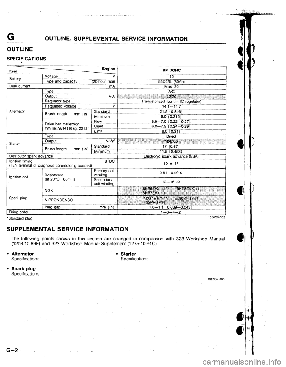
G OUTLINE, SUPPLEMENTAL SERVICE INFORMATION
SPECIFfCATfUNS
Item
8attery
Dark current Voltage
Type and capacity Engine
v
(20-hour rate)
mA BP DOHC
12
55D23L (60Ah)
Max. 20
Type Output V-A f “‘i j.,: i .:.. ‘:.. ,, j j.: i.‘: ;:;:i :j;&?.:. .: .:.
__ : . . s.i-....‘:‘:. _.. j ;.’
Regulator type Transistorized (built-in IC regulator)
Regulated voltage v
14.1-14.7
I
C?*..*rlrrrl
Brush length mm [rn] }e 21.5 (0.846)
8.0 10.315)
I Drive belt deflection I 5.5-7.0 { 0.22-0.27 )
mm (intB8N (lOkgf,22Ibf) usea 6.0-7.5 (0.24-0.29 1
Limit 8.0 (0.311
, Type Direct
Starter Output v*$# : : ;..;. ‘:‘.. ._ .; : :‘: 7.:
.. .::“:.:j 1 ,5
. . . . .j$$g;g$y .“. :yy
Brush length mm {in] - Standard 17 [0.67]
Minimum
11.5 IO.4531
Dlstnbutor soark advance Electronic soark advance (ESA)
@EN termind of diagnosis connector grounded) II) f lo
I 1 Prtmary coil
**4 nn*
Ignltbon co11 Reststance 3
(at 20°C [68*F])
in IO-16 kQ lgnrtlon timing BTDC f ar
wrndfnb
I
Secondary 1
coil WindIn.. v.0 I
--v.yy 1
Spark plug NGK
NIPPONDENSU
Firing oraer
*Standard pfug
SUPPLEMENTAL SERVICE INFORMATION
The following points shown in this section are changed in comparison with 323 Workshop Manual
(1203-l O-89F) and 323 Workshop Manual Supplement (I 275-l O-91 C).
l Alternator . Starter
Specifications Specifications
l Spark plug
Specifications
13EGGX-303
G-2