engine MAZDA 323 1992 Suplement Repair Manual
[x] Cancel search | Manufacturer: MAZDA, Model Year: 1992, Model line: 323, Model: MAZDA 323 1992Pages: 279, PDF Size: 24.15 MB
Page 159 of 279

TO TECHNICAL DATA
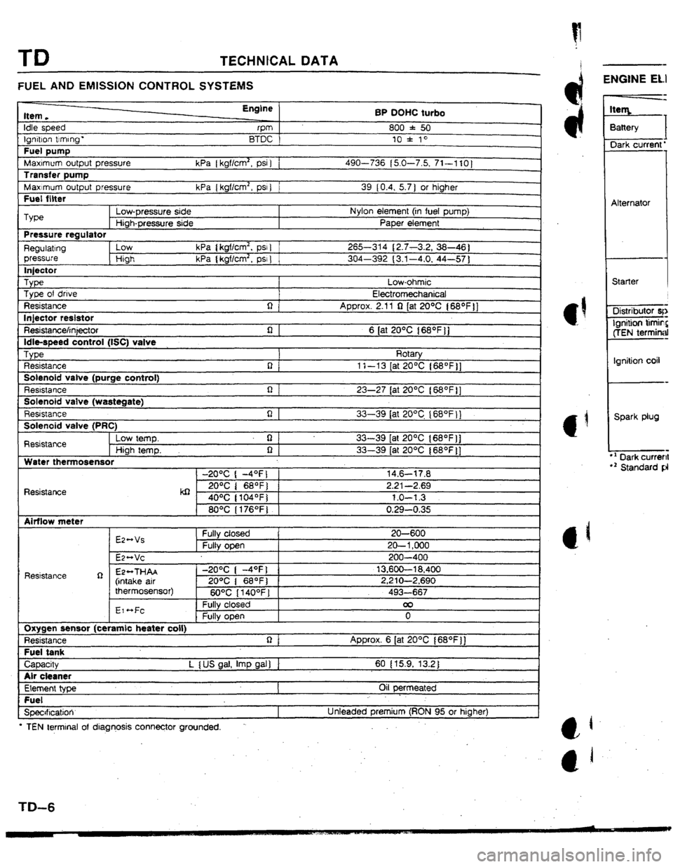
FUEL AND EMISSION CONTROL SYSTEMS
Item.
Idle speed
tgf-don trrmng-
Fuel pump
MaxImum output pressure
Transfer pump
Maximum output pressure
Fuel filter Engine
rPm
BTDC
kPa [ kgf/cm2, psi 1 1
kPa { kgflcm2, PSI ) 1 BP OUHC turbo
800 f 50
10 l 10
490-736 (5.0-7.5, 71-1 IO]
39 10.4, 5.7 ) or higher
I Type
Low-pressure side Nylon element (in fuel pump)
Hiah-Dressure side PaDer element
Pressure regulator
Regulating low kPa ( kgflcm2, psr 1 265-314 (2.7-3.2, 38-46 1
pressure High kPa { kgflcm2, psr 1 304-392 (3.1-4.0, 44-57 1
lniector
_ Type Low-ohmic
Type of drive
Electromechanical
Resistance q
Approx. 2.11 Q (at 20% ( 68*f )]
lniector reslstor
L - Resistance/injector
Idle-speed control (tSC) valve
TvDe n 1 6 [at 20°C 168OFjj
I Rotarv
Resistance
Solenoid valve (purge control)
Resbstance
Solenoid valve {wastegate)
Resistance n(
R I
i-l I 1 t-13 [at ZO*C {68OF j]
23-27 tat 20°C l68OFll
. r.
33-39 lat 20°C I68OF 11
Solenoid valve (PRC)
Resistance Low temp. q
33-39 [at 2O*C {SS*F]]
High temp. 0 1 33-39 [at 20°C (68OF]]
Water thermosensor
-20°C ( -4OFJ 1 14.6-17.8
Resistance kQ 2o”c I 68OF) 2.21-2.69
40°C ( tO4OF) 1.0-l 3
80°C I176OFJ 0.29-0.35
Airflow meter
Resistance R E244Vs
E2*Vc Fuity closed
Fully open I 20-600
20- 1,000
200-400
EP++THAA
(intake air
thermosensor) -2O*C ( -4OFj 1 13,600-l 8,400
20% 1 68OF) 1 2,210-2,690
6O*C 114OOFl i 493-667
EI ~Fc
I Fully closed 00
0 1
Oxygen sensor (ceramic beater coil)
Resistance
Fuel tank Approx. 6 [at 20°C f68OF)]
I CaDacW L I US oal. ImD aal I I 60 I 15.9, 13.2 I
I
Air cleaner
Element type
Fuel
Specrficatioir Oil permeated
Unteaded premium (RON 95 or higher)
l TEN terminal of diagnosis connector grounded. .
-
ENGINE ELI
3attery
I
Dark current’
Alternator
Starter
Distributor qr
Ignition timin?
ffEN terminal
Ignition coil
Spark plug
l ’ Dark current
r2 Standard pl
Page 160 of 279

TECHNICAL DATA TD
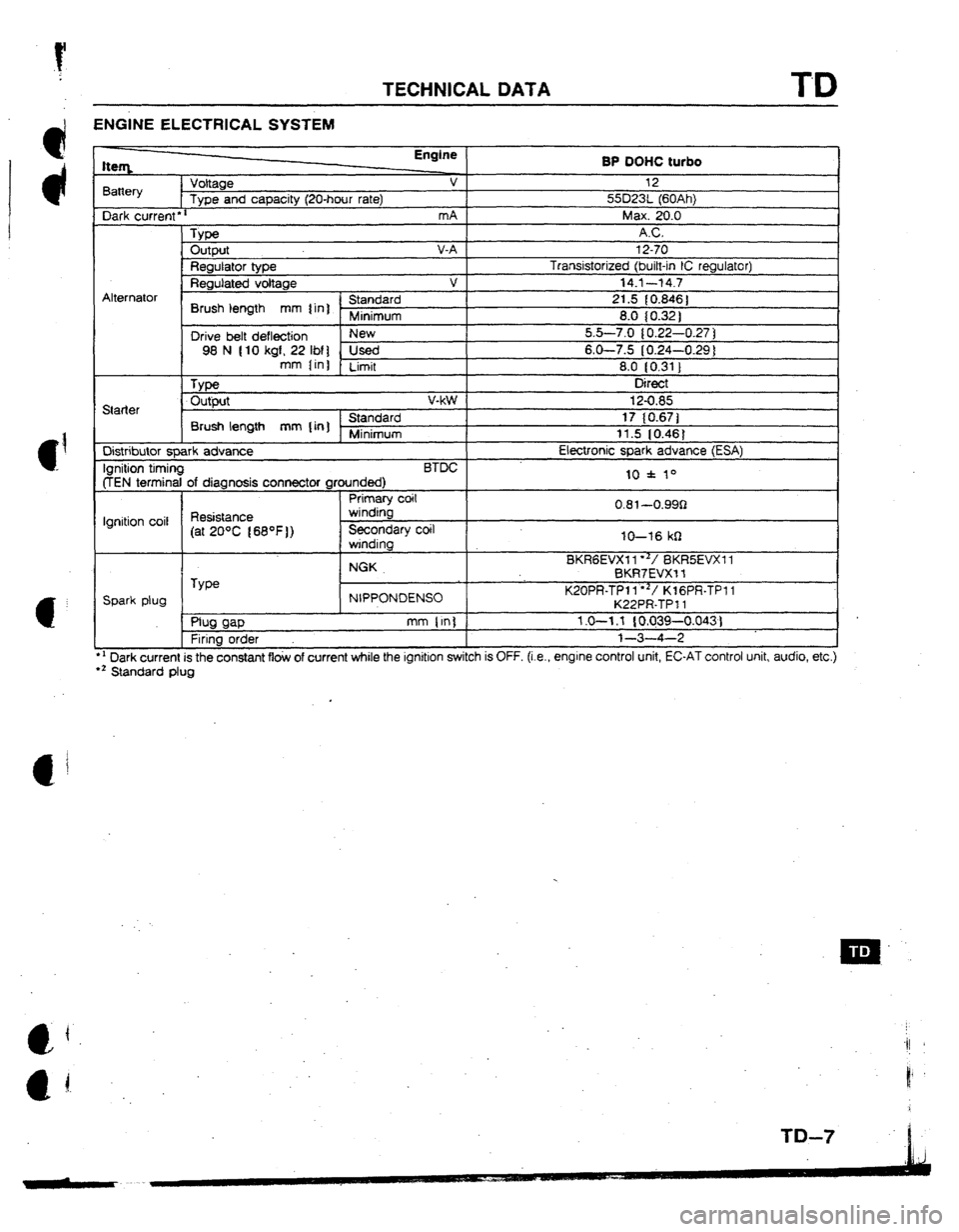
ENGINE ELECTRICAL SYSTEM
l ’ Dark current is the constant flow of current while the ignition switch is OFF. (i.e., engrne control unit, EC-AT control unit, audio, etc.)
l z Standard plug tteq Engine
BP OOHC turbo
Battery Voltage v 12
Type and capacity (2U-hour rate) 55D23t (60Ah)
Dark current
l r mA Max. 20.0
_ Type AC.
Output V-A 12-70
Regulator type Transistorized (bitt-in IC regulator)
Regutated voltage v 14.1--t4.7
Alternator
’ Standard
Brush length mm 1 in] r 21.5 { 0.846 ]
Minimum 8.0 (0.32 )
Drive belt deflection New 5.5-7.0 10.22-0.27 ]
98 N (10 kgf, 22 IM] Used 6-O-7.5 (0.24-0.29 1
mm Iin)
Limit 8.0 IO.31 1
, Type Direct
Starter Output v-kW
Standard
Brush length mm {in] Minimum
Distributor spark advance
Ignition timing BTDC
(TEN terminal of diagnosis connector grounded)
Primary coit
Ignition coil Resistance winding
(at 20°C 168OF)) Secondary coil
winding
NGK
TYW
Spark plug NIPPONDENSO
, ml WP mm (in)
Firing order 12-0.85
17 (0.671
11.5 IO.481
Etectronic spark advance (ESA)
10 f 10
0.81~-0.99Q
IO-16 kfI
BKRGEVXI I**/ BKRSEVXI 1
BKR7EVX-f f
K20PR-TPl l”‘/ KlGPR-TPI 1
K22PR-TP 11
1.0-l .f { 0.039-0.043)
l-3-4-2
Page 161 of 279
![MAZDA 323 1992 Suplement Repair Manual TD TECHNICAL DATA
CLUTCH
Jmn -
Clutch control
Clutch oedat Engine/Transaxle BP DOW turbo
G25MX-R {G5MX-R)
Hydraulic Type I
Suspended
Pedal ratio mm [in) 6.55
Full stroke mm {in] 135 t5.311
H MAZDA 323 1992 Suplement Repair Manual TD TECHNICAL DATA
CLUTCH
Jmn -
Clutch control
Clutch oedat Engine/Transaxle BP DOW turbo
G25MX-R {G5MX-R)
Hydraulic Type I
Suspended
Pedal ratio mm [in) 6.55
Full stroke mm {in] 135 t5.311
H](/img/28/57055/w960_57055-160.png)
TD TECHNICAL DATA
CLUTCH
Jmn -
Clutch control
Clutch oedat Engine/Transaxle BP DOW turbo
G25MX-R {G5MX-R)
Hydraulic Type I
Suspended
Pedal ratio mm [in) 6.55
Full stroke mm {in] 135 t5.311
Height (With carpet) mm [in] 196-204 (7.72-8.03 1
Free play mm (in] 5.5-l 7.4 {0.22-0.69 ]
Distance to carpet when clutch fully
disengaged mm [in) Minimum 41.0 (1.61 ]
Flywheel
Runout limit mm {in] 0.200 [ 0.0079)
Clutch disc
1
, Type I Single dry plate
Runout limit mm (in) 0.700 [ 0.0276 )
Wear limit mm {in] 0.3 [ 0.012 ] from rivet head
Outer diameter mm {in] 230 {9.05)
Inner diameter mm {in) 155 i6.10)
Facing thickness mm [in] Flywheel side
I 3.5 (0.14)
Pressure elate side 3.5 10.141
Clutch cover
Type
Set load
Ctutch fluid
Type I
N [kgf, Ibf) 1
I Diaphragm spring
5,494 1560, 1,232)
SAE J1793 or FMVSS116 DOT-3 MANUAL TRANSAXLE AND TRANSFER
SpecMcation
Transaxle type
Transaxle control
Transaxle shift control
Syncromesh system G25MX-R (G5MX-R)
Floor shift
Cable
Forward: Synchromesh
Reverse: Seiective sfidina and svnchromesh
I 1 st 3.454 a
2nd 1.833
3rd 1.310
Gear ratio
4th 0.970
5th 0.717
Reverse 3.166
Final gear ratio I . 4.214
Speedometer gear ratio (Driven gear/drive gear) 1.045 (23122)
Grade API service GL-4
011 Viscocity AkeaSQn: ATF Dexron@II or M-ID
Above -l8*C (OOF): SAE 75W-90
Capacity L {USqt, Imp itI 2.6 12.7, 2;2]
Runout
Primary shaft gear runout
Secondary shaft gear runout mm {in) 0.050. [ 0.0020 ]
mm [in] 0.015 { 0.0006 ]
Clearance
1st’ (Gear inner dia. -shaft puter dia)
2nd (Gear inner dia. -shaft outer dia)
3rd {Gear inner dia. -shaft outer dia)
4th (Gear inner dia. -shaft outer dia)
5th (Gear rnner dia. -shaft outer diaj mm {in] 1 0.030-0.080 { 0.0012-0.0~3 11
mm {in) 0.030~0.08C (-0.0012-0.0031 1
mm (in) 0.030-0.080 I 0:0012-0.003i 1
mm [in] 0.030-0.080 [ 0.0012-0.0031 ]
mm [lnl 0.030--0.080 ~0.0012-0.0031 1
1. TD-8
Lern
l-2 sift for
3-4 shift fri
5th shift f;t
Reverse iti
Thrust cli
1st gear
2nd gear
3rd gear
4th gear
5th gear
. .
Primary St
Seconda:
Center ci
Type :
Number
c
Number (
Number r
Number ;
Bearing ;
Bearing
1
End plai
Ring get
End pi&i
Sun gea
frltnsfe~
Final g&f
Number
Page 163 of 279
![MAZDA 323 1992 Suplement Repair Manual TD TECHNICAL DATA
Hem Engine
SP DOHC turbo
Note ) I
1 st and 2nd
Synchronizer ring outer diameter
’ I 67.7 I2.665)
mm [in] 3rd and 4th 67.7 12.665 )
5th and reverse 55.7 t2.192)
Synchronize MAZDA 323 1992 Suplement Repair Manual TD TECHNICAL DATA
Hem Engine
SP DOHC turbo
Note ) I
1 st and 2nd
Synchronizer ring outer diameter
’ I 67.7 I2.665)
mm [in] 3rd and 4th 67.7 12.665 )
5th and reverse 55.7 t2.192)
Synchronize](/img/28/57055/w960_57055-162.png)
TD TECHNICAL DATA
Hem Engine
SP DOHC turbo
Note ) I
1 st and 2nd
Synchronizer ring outer diameter
’ I 67.7 I2.665)
mm [in] 3rd and 4th 67.7 12.665 )
5th and reverse 55.7 t2.192)
Synchronizer key dimension 1st and 2nd @ 19.0 {0.748], 04.3 (0.171, 05.0 10.20)
mm [in] 3rd and 4th @ 17.0 10.669J, 04.3 (0.171, @ 5.0 lO.20)
5th and reverse 0 17.0 10.6691, m4.3
10.171, @I 5.0 fO.201
PROPELLER SHAFT
Item
length
Outer diameter Engineflransaxie Model BP DOHC turbo
G25MX-R (GSMX-R)
Front 834.3 { 32.85 ]
mm fin] Center 584 122.99)
Rear
I 437 { 17.20)
Front 75 (2.95)
mm { in] Center 57 12.24) f
Rear 57 12.241
FRONT AND REAR AXLES
Item Specifications
Front driveshaft
Jomt type Inside Double oftset joint
Outside Bell jotnt
Length of joint (between center of joint) mm { rn t - Right 392 (15.4)
left 306 (0.83 ]
Shaft diameter mm {in] 21.0 to.831
I
Rear driveshaft
Joint type Inside 1
Outside 1
Length of joint (between center of joint) mm [in ] ’ Right
Left
Shaft diameter mm (in)
J&t shatt
Length of joint
Shaft diameter
Front axle
Bearing play axial direction mm [in] 1
Rear axle
Bearing play axial direction mm lin] 1
Rear differential (viscous limited slip differential) Double offset joint
Bell joint
519.5 (20.5 ]
489.5 [f9.3]
21.0 IO.831
357.2 1 t4.11
21 .O (0.83 )
0.050 IO.002 ]
0.050 (0.002 ]
*
Reduction gear
Different ia gear
Oifferential ratro
Number of teeth
Flurd
L Ring gear
Drive .pinion gear
Grade
Viscosity Above -18*C fO*F ]
Below -18*C lOoF)
, Capacity
L fUS qt, Imp c$l Hypoid gear
Straight bevel gear
3.909
43
11
API Service GL-5
SAE 90
SAE 80W
0.65 lQ.69, 0.571 STEERING SI
1 Free olav 8RAKING SY
Brake type
Brake pedat
Height
Free play 1
Reserve travel
Clearance whet
Master cylinde
Master cylinder
Front disc brai
. Tyl?e
Thickness of p&
Thickness of pa
Page 168 of 279

ST
SPECIAL TOOLS
c 1
GENERAL lNFORMATlON ........................ ST- 2
ENGINE
..................................................
ST- 3
CLUTCH AND MANUAL TRANSAXLE
........
ST- 4
FRONT AND REAR AXLES.
...................... ST-
5
STEERING ..............................................
ST- 6
BRAKING ...............................................
ST- 8
FRONT AND REAR SUSPENSION..
........... ST- 9
CHECKER AND OTHER EQWPMENT..
.......
ST-IO
13ESTX-301
c I
__
c I
Page 169 of 279

ST SPECIAL TOOLS
GENERAL INFORMATION
The letters A and B in the priority column indicate the degree of importance of each tool.
A. . . . . Indispensable
The toots ranked A in this list are indispensable for performing operations satisfactorily, easily, safely, and
efficiently. It is, therefore advisable that all service shops have these tools.
B.. . . .Selective
The tools in this list are not as necessary as tools ranked A, but all service shops should have these tools
to perform repairs more easily and more efficiently.
Note
l When ordering toot sets that consist of several tools, check the List in the Parts Catatogue
to make sure that some tools are not duplicated in other sets you may already have. tf they
are, instead of ordering the set, order only those new tools that are needed.
l There are new SST explanations in this tool chart.
These tools are indicated by “NEW SST” in description column.
13ESTX.302 49 OlC7
Engine
49 LOY~
Hanger
engiN
49 063
Arm, \I lifter
49
BO
Pivot
. .-
49 Sl
Rem
aeaf
Brakl
Page 170 of 279

SPECIAL TOOLS ST
ENGlNE
TOOL NUMBER
b DESCRIPTION PRlORlTY ILLUSTRATlON
49 0107 680A
Engine stand A
49 LO10 IA0
Hanger set,
engine stand
49 0636 IOOA
Arm, valve spring
lifter
49 8012 OA2
Prvot
A
49 5120 170
1 I
Remover, valve
seal
A ff==cB
49 E011 IA0
Brake, ring gear A Installer set, valve
seal & valve
Remover &
installer, valve
49 0221
061A
49 DO11
102
Lock tool,
crankshaft
- 49 GO14
001
Wrench, tit filter
49 9200 145
Adapter, radiator
Page 179 of 279

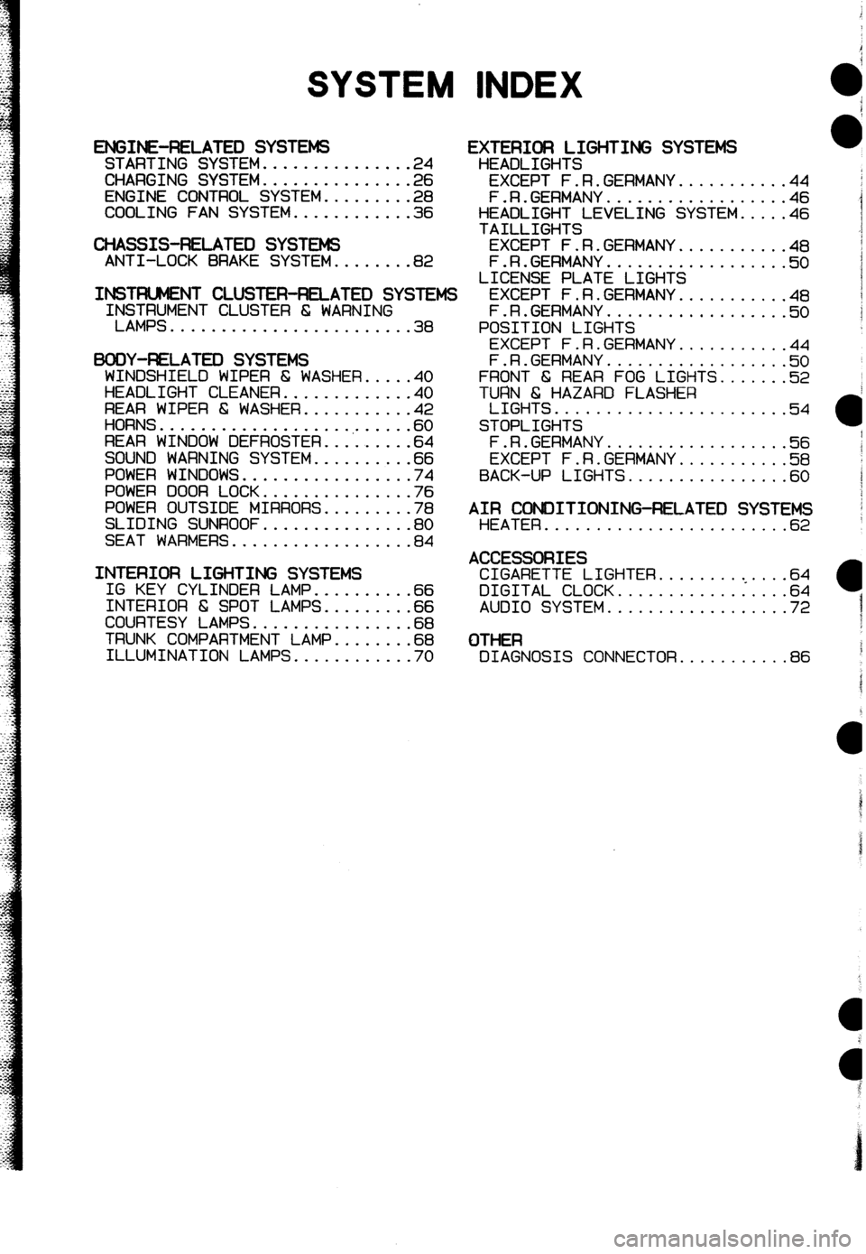
SYSTEM INDEX
ENGINE-RELATED SYSTEMS STARTING SYSTEM...............2 4
CHARGING SYSTEM...............2 6
ENGINE CONTROL SYSTEM.........2 8
COOLING FAN SYSTEM............3 6
CHASSIS-RELATED SYSTEMS ANTI-LOCK BRAKE SYSTEM........82
INSTFUJMENT CLUSTER-RELATED SYSIEMS IrS$;MENT CLUSTER 6 WARNING
........................ 38
BODY-F&LATEX) SYSTEMS
WINDSHIELD WIPER 6 WASHER.....4 0
HEADLIGHT CLEANER.............4 0
REAR WIPER & WASHER...........4 2
HORNS...................,......6 0
REAR WINDOW DEFROSTER.........6 4
SOUND WARNING SYSTEM..........6 6
POWER WINDOWS.................7 4
POWER DOOR LOCK...............7 6
POWER OUTSIDE MIRRORS.........7 8
SLIDING SUNROOF...............8 0
SEAT WARMERS..................8 4
INTERIOR LIGHTING SYSTEMS IG KEY CYLINDER LAMP..........6 6
INTERIOR 6 SPOT LAMPS.........6 6
COURTESY LAMPS................6 8
TRUNK COMPARTMENT LAMP........6 8
ILLUMINATION LAMPS............7 0
EXTERIOR LIGHTING SYSTEMS
HEADLIGHTS
EXCEPT F.R.GERMANY...........44
F.R.GERMANY..................46
HEADLIGHT LEVELING SYSTEM.....46
TAILLIGHTS
EXCEPT F.R.GERMANY...........48
F.R.GERMANY..................5 0
LICENSE PLATE LIGHTS
EXCEPT F.R.GERMANY...........4 8
F.R.GERMANY..................5 0
POSITION LIGHTS
EXCEPT F.R.GERMANY...........4 4
F.R.GERMANY..................!i? 0
FRONT 6 REAR FOG LIGHTS.......52
TURN 6 HAZARD FLASHER
LIGHTS.......................54
STOPLIGHTS
F.R.GERMANY.a................5 6
EXCEPT F.R.GERMANY...........5 8
BACK-UP LIGHTS................6 0
AIR CONDITIONING-RELATED SYSTEMS HEATER........................6 2
ACCESSORIES CIGARETTE LIGHTER.........<....64
DIGITAL CLOCK.................64
AUDIO SYSTEM..................72
OTHER DIAGNOSIS CONNECTOR...........86
Page 185 of 279

GI Reading Wiring Diagrams
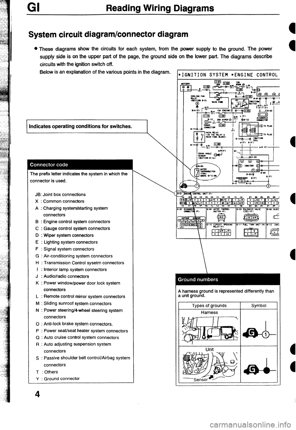
System circuit diagram/connector diagram
l These diagrams show the circuits for each system, from the power supply to the ground. The power
supply side is on the upper part of the page, the ground side on the lower part. The diagrams describe
circuits with the ignition switch off. Below is an explanation of the various points in the diagram.
I Indicates operating conditions for switches.
I
The prefix letter indicates the system in which the
:onnector is used.
JB: Joint box connections
X : Common connectors
A : Charging system/starting system
connectors
B : Engine control system connectors
C : Gauge control system connectors
D : Wiper system connectors
E : Lighting system connectors
F : Signal system connectors
G : Air-conditioning system connectors
l-l : Transmission Control sysetm connectors
I : Interior lamp system connectors
J : Audio/radio connectors
K : Power window/power door lock system
connectors
L : Remote control mirror system connectors
M : Sliding sunroof system connectors
N : Power steering/4-wheel steering system
connectors
0 : Anti-lock brake system connectors.
P : Power seat/seat heater system connectors
Q : Auto cruise control system connectors
R : Auto adjusting suspension system
connectors
S : Passive shoulder belt control/Airbag system
connectors
T : Others
Y : Ground connector
4
IGNITION SYSTEM mENGINE CONTROL
A harness ground is represented differently than
a unit ground.
Types of grounds
Harness
Unit Symbol
Page 188 of 279

Reading Wiring Diagrams GI
HARNESS SYMBOLS
DESCRIPTION OF HARNESS
FRONT HARNESS
ENGINE HARNESS
INSTRUMENT PANEL HARNESS
REARHARNESS
REAR NO.2 HARNESS
REAR NO.3 HARNESS SYMBOL
F) TTT
E) m
(1) %4l
(W
VW m
(R3) DESCRIPTION OF HARNESS
EMISSION HARNESS
INJECTOR HARNESS
INTERIOR LAMP HARNESS
FLOOR HARNESS
DOOR NO.1 HARNESS
DOOR NO.2 HARNESS
NSTRUMEN\T\PANEL HARNESS (I)
FROM; HARNESS(F) SYMBOL
INTERIOR LAMP HARNESS (IN)