vacuum MAZDA 323 1992 Workshop Manual Suplement
[x] Cancel search | Manufacturer: MAZDA, Model Year: 1992, Model line: 323, Model: MAZDA 323 1992Pages: 279, PDF Size: 24.15 MB
Page 34 of 279

F3
c
FUEL AND EMISSION
CONTROL
SYSTEMS
i
INDEX . . . . . . . . l ..,.... *..,. . . . . . . m...*.*...*..... F3- 2
UUTLtNE
...................................... F3- 4
OUTLINE OF CONSTRUCTION.. ....
F3- 4
SYSTEM DIAGRAM ...................... F3- 5
VACUUM HOSE ROUTING
DIAGRAM
................................. F3- 6
WIRING DIAGRAM.. .....................
F3- 7
ECU RELATIONSHIP DIAGRAM ...... F3- 8
SPECIFICATIONS.. ....................... F3- 9
TURBOCHARGER CONTROL .......... F3-IO
OUTLINE
.................................... F3-10
SYSTEM DIAGRAM ...................... F3-10
WASTEGATE CONTROL ............... F3-11
FUEL SYSTEM
.............................. F3-12
OUTLINE ....................................
F3-12
CONTROL SYSTEM .......................
F3-13
STRUCTURAL VIEW .....................
F3-13
PRESSURE REGULATOR
CONTROL SYSTEM ....................
F3-14 SUPPLEMENTAL SERVICE
tNFOF?MATtON
............................. F3-I 5
SELF-DtAGNOStS FUNCTtON.. ........
F3-16
OUTLINE ....................................
F3-16
SERVICE CODE NUMBERS..
......... F3-16
TROU8LESHOOTtNG GUtDE
........... F3-19
RELATIONSHtP
CHART.. F3-19 ..............
DIAGNOSTIC JNDEX
.................... F3-20
PRECAUTIONS
............................
F3-21
SYMPTOM TROUBLESHOOTING .... F3-22
TURBOCHARGERCONTROL
SYSTEM ......................................
F3-37
TURBOCHARGER F3-37 ........................
WASTEGATE SOLENOID VALVE.. .. F3-38
INTERCOOLER ............................
F3-39
FUELSYSTEM ..............................
F3-40
FUEL PUMP ................................
F3-40
FUEL PUMP RESISTOR/RELAY ......
F3-40
PRESSURE
REGULATOR .............. F3-41
INJECTOR ..................................
F3-42
INJECTOR RESISTOR
................... F3-42
PRESSUR REGULATOR CONTROL
SYSTEM ......................................
F3-43
SOLENOID VALVE (PRESSURE
REGULATOR CONTROL)
............. F3-43
CONTROL SYSTEM
....................... F3-44
PREPARATION ............................ F3-44
ENGINE CONTROL UNIT (ECU) ..... F3-45
7 3EOF3-301
Page 39 of 279
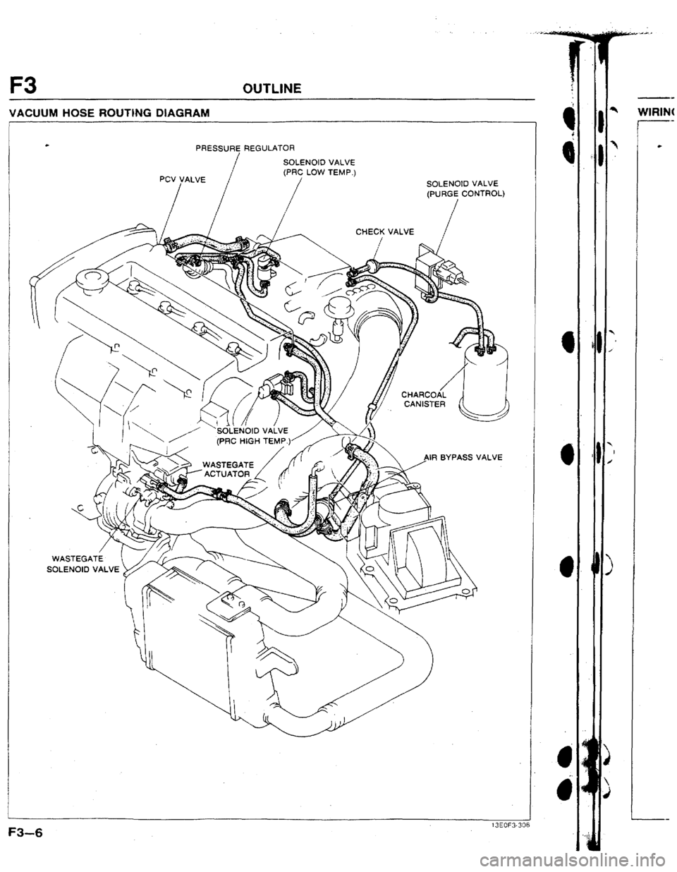
F3 OUTLINE
VACUUM HOSE ROUTING DIAGRAM
PRESSURE REGULATOR
IF1 BYPASS VALVE
Page 45 of 279

F3 FUEL SYSTEM
FUEL
SYSTEM
OUTLINE
l Thspressure regulator has two vacuum ports for its two-stage operation. (Refer to page F3-43.)
l The injectors are changed from high-ohmic type to low-ohmic type for improvement of the supply of fuel
during high-speed engine operation.
l To decrease the current in the injectors, an external resistor is equipped and is mounted on the aircleaner
housrng .
13EOF3315 Pressur regulator
VACUUM PORTS
F3-12 13EOF331;
Page 47 of 279

F3 CONTROL SYSTEM
PRESSURE REGULATOR CONTROL SYSTEM
SOLENOID VALVE TO MAIN RELAY
(PRC HIGH TEYP.)
t ECU
I
PRESSURE REGULATOR
// VACUUM
IJ WATER
THERMOSENSOR
F----------- lNTAKE AIR
THERMOSENSOR
SWITCH SOLEltolD VALVE
(PRC LOW TEMP.)
TO FUEL TANK
13EOF3-31 To prevent vaporlock in the fuel system during hot restart idle, a two-stage pressure regulator is adoped
to the new 323 4WD.
Low temperature operation: The vacuum to the pressure regulator (A and B ports) is cut (solenoid valve
[low temp.] UN), and the fuel injection pressure is increased to 284 kPa (2.90 kgf/cm2, 41 psi ) ,
High temperature operation: The vacuum to the pressure regulator (A port) is cut (solenoid valve [high
temp.] ON), and the fuel injection pressure is increased to 343 kPa [ 3.5 kgf/cm2, 49 psi 1.
Condition and operation
Condition Operation
1
coolant Intake alt Solenoid vrlve Solenoid vatve Opemtlon
I temperature temperature Engine (Idw temp.)
(high temp.) time Operation 40% [fU40f)-
Above 90°C 5U°C (t22OFI ON OFF 180s Low temp.
f f940Fj No load
Above 5O*C
I122OF) OFF ON 210s t-ltgh temp.
3
t3EOF3-319
F3-14 Wast
l Ins fuel
l In:; InJeci
l In:;
l Vol Injecl
l In:;
Presr
l SCI Engir
l InsI
Page 60 of 279

TROUBLESHOOTING GUlDE F3
7 CRANKS NORMALLY BUT HARD TO START - AFTER WARM-UP
*
l Engrne cranks at normal speed but requkres excessive cranking time before starting after running and being
DESCRIP- hot soaked
TION
l Battery rn normal condition l Engine starts normatly when cold
*Engine runs normally at Idle (If idle condrtron is not OK, refer to “Rough idle” ~Nos. 8-l 21)
[ ~ROUBLESHOOTLNG HINTS1
[ i 5 ArrlFuel mixture too Rich - l Fuel rqection control malfunction l lnpector fuet leakage
I
TEP tNSPECTlON @ Vaporlock
l Fuel pressure not held rn fuel line after engrne IS
stopped
l Pressure regulator control system malfunction
I ACTION
1 Is “00” dispiayed on Self-Diagnoses
Checker wrth rgnrtron switch ON7
SYSTEM?_SELECT. 1
SELECT SW. A
Remove vacuum hose from pressure regulator
(port A) ancI plug rt. dOt?S engine start normally’-,
Remove both vacuum hoses from pressure regu-
lator (ports A and Bj and plug them; does en-
gine start normally7
@
PtUG
/ /
Are ECU terminal voltages OK
(especially 1 C, 20, 20 and 2T)?
w page F3-46 Yes Go to next step
No Service Code No. displayed
Check for cause (Refer to specified
check sequence) CT oaae F3-16
“88” flashes
Check ECU terminal 1F voltage
Voltage: Battery voltage
(ignition switch ON) w page F3-45
( cs> It OK. replace ECU
/ w page F3-2’
3 If not OK, check wlrtng
(ECU - Self-Dlagnosrs ChecKer)
Yes Check pressure regulator control sys-
.
tern (high temperature operation) w page F3-43
I NO Go to next step
Check pressure regulator control sys-
tem (low temperature operation)
No 1 Go to next step
Yes Go to next step
NO Check for cause
F3-27
Page 61 of 279
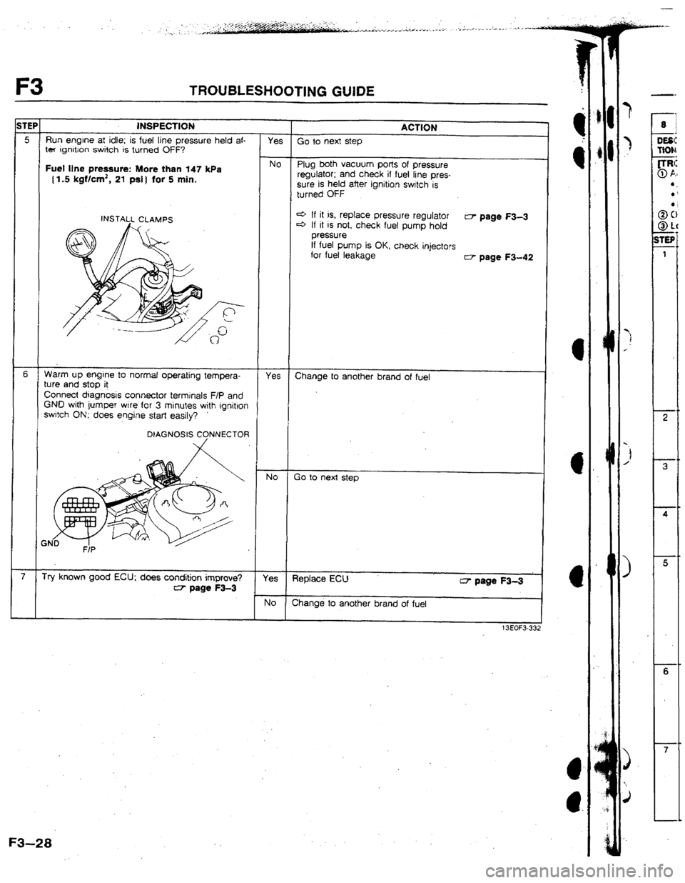
F3 TROU8LESliOOTING GUIDE
iTEP INSPECTION
ACTtUN
5 Run engine at idle; is fuel line pressure held af-
Yes Go to next step
ter ignition switch is turned OFF?
Fuet Ijne pressure: More than 147 kPa No Plug both vacuum potts of pressure
{1,5 kgflcd, 21 pdf for 5 min. regulator;
and check if fuel line pres-
sure is held after ignition switch is
turned OFF
NSTAtl CLAMPS 4 If it is, replace pressure regulator
c3 If it is not, check fuel pump hold CT page F3-3
pressure
If fuel pump is OK, check injectors
for fuet leakage
CT- page F3-4
6 Warm up engine to normal operating tempera-
Yes
ture and stop it Change to another brand of fuel
Connect diagnosis connector terminals F/P and
GND with jumper wire for 3 minutes with rgnitlon
switch ON; does engine start easily?
No Go to next step
7 Try known good ECU; does condition improve?
Yes Replace ECU
CT page F3-3 w- page F3-3
No Change to another brand of fuel
t3EOF3
F3-28
Page 63 of 279

F3 TROUBLESHUOTING GUIDE
TEPI tNSPECTION ACflON
e If OK, replace injector
4 If not OK, check for cause w Section 82
(Upper vacuum hose to pressure regulator 4
If pressure quickly increases,
check pressure regulator
4 If pressure
gradually increases,
check for clogging between fuel
pump and pressure regulator
if hose is not clogged, check fuel
pump maximum pressure
I
12 Is engine compression correct? Yes Go to next step w Sectlon 82
Engine
compression: 1059 kPa (10.8 kgf/cm2, 152 psi]-300 rpm NO Check for cause w Section B2.
13 Connect System Selector to diagnosis connector
Yes Try known good ECU; does condition
and $et Test Switch to SELF TEST; is ignition improves? w page f3-3 timing correct at idle after warm-up?
ignition timing (BTDC): 10 * to
NO Adjust ignition timing
F3-30
7
*
10
DES&
HON
-*
ITEP
2
3
4
Page 64 of 279

TROUSLESHOOTING GUIDE F3
10 ROUGH IDLE/ENGINE STALLS AT IDLE - AmER WARM-UP
DESCRIP- -Engine runs normalty at idle during warm-up but engine stalls or vibrates excessively after warm
TlO#
TROUBLESHOOTING HINTS]
3 Idle-speed control system malfunction
3 Air/Fuel mixture too lean
l Air leakage
*Low fuel line pressure
TEP
INSPECTION
1
ts “00” dlsplayed on Se\-Diagnosis Checker
with ignition switch ON?
SYSTEM SELECT: 1 @ Air/Fuel mixture too rich
l Fuel injection control malfunctlon
(correction for coolant tem$eratuie)
@ Poor ignition
@ Low engine compresslon
ACTION
YES Go to next step
No Service
Code No. displayed
Check for cause (Refer to specified
check sequence)
w page F3-16
“88” flashes Check ECU terminal IF voltage w page F345
Voltage: Battery voltage
(ignition switch ON)
W: SELF TEST e !f UK, replace ECU
w page F3-3 c3 ff not OK, check wiring
(ECU - Self-Diagnosis Checker)
2 Are ECU termrnal voltages OK Yes Go to next step
(especially 20, 20, and 2Q)?
w page F3-45 No
Check for cause
3 Disconnect each high-tension lead at idle; does Yes Go to next step
engine speed decrease equally at each cylinder?
NO Go to Step 9
4 Is intake manifold vacuum correct at idle? Yes Go to next step
Vacuum: More than 450 mmHg f 17.7 InHg )
NO Check for air leakage of intake air sys-
tem components
5 Is air cleaner element clean? Yes Go to next step
No Replace air cleaner element
F3-3 1
Page 65 of 279
![MAZDA 323 1992 Workshop Manual Suplement F3 TROUBLESHOOTING GUIDE
3TEI ACTION
Is fuel line pressure correct at Idle?
*
Fuel line pressure: 265-314 kPa
12.7-3.2 kgf/cm’, 38-46 psi]
(Two vacuums hose to pressure regulator
disconnected](/img/28/57055/w960_57055-64.png "MAZDA 323 1992 Workshop Manual Suplement F3 TROUBLESHOOTING GUIDE
3TEI ACTION
Is fuel line pressure correct at Idle?
*
Fuel line pressure: 265-314 kPa
12.7-3.2 kgf/cm’, 38-46 psi]
(Two vacuums hose to pressure regulator
disconnected")
F3 TROUBLESHOOTING GUIDE
3TEI ACTION
Is fuel line pressure correct at Idle?
*
Fuel line pressure: 265-314 kPa
12.7-3.2 kgf/cm’, 38-46 psi]
(Two vacuums hose to pressure regulator
disconnected)
304-392 kPa [ 3.1-4.0 kgf/cm’, 44-57 psi 1
(Upper vacuum hose to pressure regulator
disconnected)
INSTALL CLAMPS Yes Go to next step
No Low pressure
Check fuel line pressure while pinching
fuel return hose
4 If pressure quickly Increases,
check pressure regulator
e If pressure gradually Increases,
check for clogging between fuel
pump and pressure regulator
If hose is not clogged, check fuel
pump maxrmum pressure
Connect System Selector to diagnosis connector
and set Test Switch to SELF TEST; is ignition
tlmlng at idle correct after warm-up?
Ignition timing (BTDC): 10 f lo Yes Go to next step
No Adjust tgnrtkon system
8 Dtsconnect water thermosensor connector; does
engine condrtlon Improve? Yes Replace water thermosensor
No
Try known good ECU. does condltlon
Improve?
w page F3-13
Go to next step
Check if injector resistance is OK
w page F3-42 9 Is jqector operating sound heard at Idle?
Yes
No
Resistance: Approx. 2.11 Q
(at 20°C 168*F])
4 If it is, check wlnng
(ECU - Injector)
c3 If it Is not, replace injector
Go to next step IO
Yes Is engine compressron cprrect?
w Section G
No
Engine compression:
1059 kPa 110.8 kgf/cm2, 152 psi)-300 rDm
is strong blue spark vrslble at each disconnected
hrgh-tension lead?’ Check engine
3 Section B2
17
Yes Go to next step
No Check high-tension lead
w Section G
c3 If UK, check distrrbutor cap and
rotor
3 If not OK, replace htgh-tensron lead
Try known good ‘ECU: does condrtron
Improve7
w page F3-3 12 Are spark plugs.OK?
w Section G
l Wear and carbon butld up l Piug gap l Damage Yes
NO
Clean, adjust
13EOi3.334
F3-32.
Page 66 of 279
![MAZDA 323 1992 Workshop Manual Suplement TROUBLESHOOTING GUlbE F3 1
14 IDLE MOVES UP AND DOWN/IDLE HUNTS
IESCRLP-
l Engine speeds up and down periodically at idle
UON
TROUBLESHOOTING HINTS]
B Idle switch (En throttle sensor) OFF at idl](/img/28/57055/w960_57055-65.png "MAZDA 323 1992 Workshop Manual Suplement TROUBLESHOOTING GUlbE F3 1
14 IDLE MOVES UP AND DOWN/IDLE HUNTS
IESCRLP-
l Engine speeds up and down periodically at idle
UON
TROUBLESHOOTING HINTS]
B Idle switch (En throttle sensor) OFF at idl")
TROUBLESHOOTING GUlbE F3 1
14 IDLE MOVES UP AND DOWN/IDLE HUNTS
IESCRLP-
l Engine speeds up and down periodically at idle
UON
TROUBLESHOOTING HINTS]
B Idle switch (En throttle sensor) OFF at idle
3 Air leakage
3 Fuel injection amount Inconstant
. Poor contact point inside airflow meter
9 Poor ignitron
rEP[ INSPECTION
I is “00” displayed on Self-Dragnosis Checker
with ignrtron swatch ON?
SYSTEM SELECT: i I ACTfON
Yes Go to next step
NO Service Code No. displayed
Check for cause (Refer to specified
check sequence) c=;r page F3-16
“86” flashes
Check ECU terminal IF vottage csr page F345
Voltage: Battery voltage
W: SELF TEST (ignition switch ON)
SELECT SW: A
.d P/ e If OK, replace ECU CT page F3-3
c3 If not OK, check wrrjng
(ECU - Self-Dlagnosls Checker)
2 Is intake manrfold vacuum correct at idle? Yes Go to next step
Intake manifold vacuum:
More than 450 mmHg { 17.7 inHg )
No Low vacuum
Check for air leakage at intake air
system
3 Is air cleaner element clean? Yes Go to next step
No Replace abr cleaner element
4 Disconnect each hrgh-tension lead at idie; does Yes Go to next step
engine speed decrease equally at each cylinder?
No Go to Step 8
5 Are ECU terminal voltages OK? Yes Go to next step
(especially 20, 2Q, 20) -
rI7 page F345 No
Check for cause
6 Connect System Selector to diagnosis connector Yes Go to next step
and set Test Switch to SELF TEST; is ignition
timing at idle correct after warm-up?
Ignition timing (BTDC): f 0 f la
No Adjust ignition timing
._
. F3-33