vacuum MAZDA 323 1992 Suplement User Guide
[x] Cancel search | Manufacturer: MAZDA, Model Year: 1992, Model line: 323, Model: MAZDA 323 1992Pages: 279, PDF Size: 24.15 MB
Page 74 of 279
FUEL SYSTEM F3
13EOF3.34
c I 13EOF3-364 FUEL PUMP CONNECTOR
/
!NSTALL CLAMPS
I
l nspection
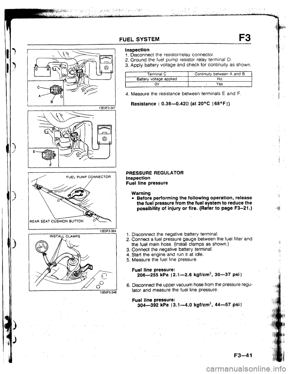
1, Disconnect the resistor/relay connector.
2. Ground the fuel pump resistor relay terminal D.
3. Apply battery voltage and check for continuity as shown.
Terminal C
Continuity between A and I3
Battery voltage applied NO
ov Yes
4. Measure the resistance between terminals E and F.
Resistance : 0.38--0.42Q (at 2O*C {6S°F 1)
PRESSURE REGULATOR
Inspection
Fuel line pressure
Warning
l Before performing the following operation, release
the fuel pressure from the fuel system to reduce the
possibility of injury or fire. (Refer to page F3-21.)
1. Disconnect the negative battery terminal.
2. Connect a fuel pressure gauge between the fuel filter and
the fuel main hose. (install clamps as shown.) , .
I
3. Connect the negative battery terminal.
/t.
4, Start the engine and run it at idle.
5. Measure the fuel line pressure.
Fuel line pressure:
206-255 kPa [ 2.1-2.6 kgflcml, 30-37 psi )
6. Disconnect the upper vacuum hose from the pressure regu-
lator and measure the fuel line pressure.
Fuel line pressure:
304-392 kPa (3.1-4.0 kgf/cm2, 44-57 psi )
F3-41
Page 76 of 279
. !I11
PRESSURE REGULATOR CONTROL SYSTEM F3
13EOF3353
(PRC HIGH TEMP.)
13EOF3-35:
BAl-fERY VOLTA
PRESSURE REGULATOR CONTROL
SYSTEM
SOLENOID VALVE (PRESSURE REGULATOR CONTROL)
Inspection
On-vehicte
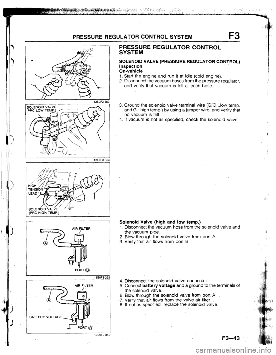
1. Start the engine and run it at idle (cold engine).
2. Disconnect the vacuum hoses from the pressure regulator,
and verify that vacuum is felt at each hose.
3. Ground the solenoid valve terminal wire (G/O...low temp.
and G. ..high temp.) by using a jumper wire, and verify that
no vacuum is felt.
4. If vacuum is not as specified, check the solenoid valve.
Solenoid Valve (high and low temp.)
1, Disconnect the vacuum hose from the solenoid valve and
the vacuum pipe..
2. Blow through the solenoid valve from port A.
3. Verify that air flows from port B.
4. Disconnect the solenoid valve connector.
5. Connect battery voltage and a ground to the terminals of
the solenoid v&e.
6. Blow through the solenoid valve from port A.
7. Verify that air flows from the valve air filter.
8. If not as specified, replace the solenoid valve.
.
F3-43
Page 114 of 279

OUTLlNE P
OUTLfNE
OUTLINE OF CONSTRUCTION
l The brake system remains similar to that of the previous model. l However, because all new models use a higher-horsepower engine, the brake system is enlarged as a whole.
l Vehicles without ABS use a portless-type master cylinder
13EOPX-303
SPECIFICATIONS
Brake pedal
Master cylinder
Front drsc brake
Rear disc brake
Power brake unit
Braking force control device
Brake fluid
Parking brake Item Specification
Type Suspended
I
PedaJ lever ratio 4.1
Max. stroke mm [in] 140 j5.511
I,
Type Tandem
Cylinder inner diameter mm {in] Without ABS: 25.4 j 1 .UO ]
With ABS: 23.8 to.941 3-
Type Ventilated disc ?
Cylinder bore mm [in)
57.2 12.253
Pad dimensions (area x thickness)
mm2 {rn2) xmm [In) 5,200 (8.OSl x 10 (0.39)
Disc plate dimensions mm (in]
(outer diameter x thickness) 274x24 (10.79x0.94)
Type Solid disc
Cylinder bore mm Jon]
34.9 j 1.37 ]
Pad dimensions (area x thrckness)
mm’ (in21 xmm [in) 3,200 I4.961 x8 (0.31)
DISC plate dimensions mm t,n]
(outer diameter x thickness) 280x10 (tl.02xu.39]
il
Type Without ABS: Vacuum multIplier
With ABS: Hydraulrc muttiplier
Diameter mm Iln]
(without ABS) 188.4 17.42) +215.2 t8.47)
We Without ABS: Dual proportioning valve
With ASS: Proportioning valve
FMVSS 116, DOT-3, SAE J1703
Mechanical twGrear-wheel control
Type
Operation system Center lever
13EOPX.304 t
Page 119 of 279

P CONVENTIONAL BRAKE SYSTEM
1 t3EOPX.314
@ 66.7 kPa
Iso0 mmHg.
19.7 inHg)
16EOPX-05t
1
13EOPX.315
P-8
POWER BRAKE UNIT
Quick Inspection (On-vehicle)
Power brake unit function check
(Method-using tester)
Connect the SST, vacuum gauge A, and pedal depression
force gauge B as shown in the figure. After bleeding the
air from the SST, conduct the test as described in the 3steps
below.
Note l
Use commercMty available vacuum gauge and ped.
al depression force gauge.
a) Checking for vacuum loss
Unloaded condition
1. Start the engine.
2. Stop the engine when the vacuum gauge reading reaches
66.7 kPa (500 mmHg, 19.7 inHg ) .
3. Observe the vacuum gauge for 15 seconds. If the gauge
shows 63.3-66.7 kPa [475--500 mmHg, 18.7-19.7
inHg 1, the unit is operating.
Loaded condition
1. Start the engine.
2. Depress the brake pedal with a fdrrce of 196 N I20 kgf,
44 Ibfj.
3. With the brake pedal depressed, stop the engine when the
vacuum gauge reading reaches 66.7 kPa {SO0 mmlig,
19.7 inHg].
4. Observe the vacuum gauge for 15 seconds. If the gauge
shows 63.3-66.7 kPa I475--500 mmHg; 18.7-l 9.7
inHg 1, the unit is operating.
b) Checking for hydraulic pressure
1, If with the engine stopped (vacuum 0 kPa (0 mmHg, 0
hltlg 1) the fluid pressure is within specification, the unit is
operating.
Pedal force N fkgf. Ibf]
Fluid pressure kPa (kgf/cm2, psi)
196 LZO. 441 1080 111. 1561 min.
2, Start the engine. Depress the brake pedal when.the vacu-
urn reaches 66.7 kPa 1500 mmHg, 19.7 intlg 1. If the flu-
id pressure is within specification, the unit is operating.
Pedal force N 1 kgf, fbf I Fluid pressure .kPa { kgflcm’. ps 1
196 I20,441 6670 {68, 967
1 min.
-- WlTHOU
&
d
I=-
-
1 MASTER CYUh
.
i_