fuel MAZDA 6 2002 Workshop Manual Suplement
[x] Cancel search | Manufacturer: MAZDA, Model Year: 2002, Model line: 6, Model: MAZDA 6 2002Pages: 909, PDF Size: 17.16 MB
Page 207 of 909
FUEL SYSTEM
F2–55
F2
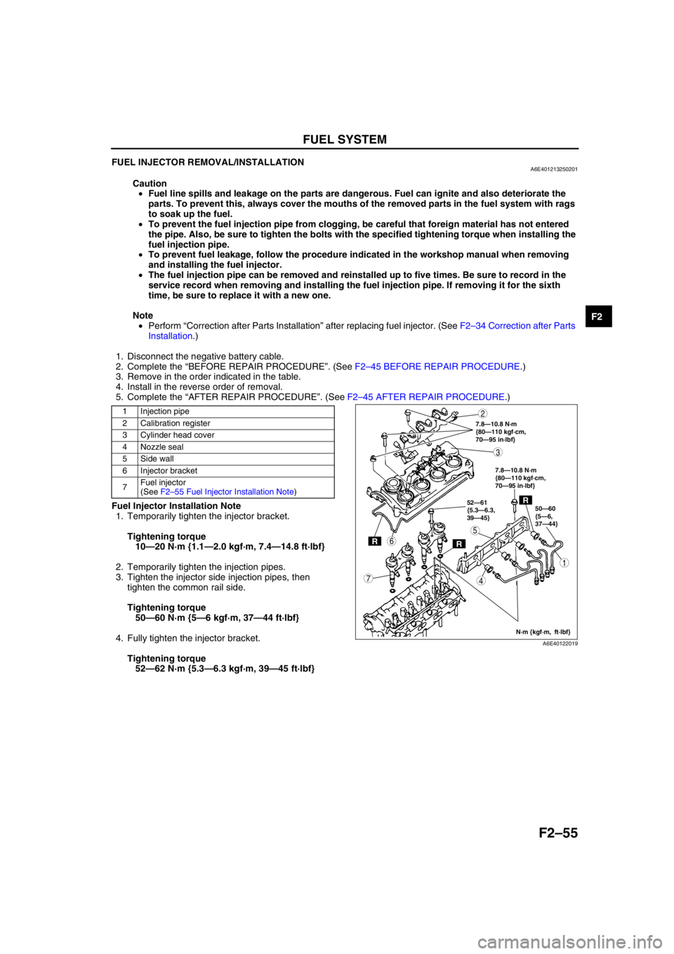
FUEL INJECTOR REMOVAL/INSTALLATIONA6E401213250201
Caution
•Fuel line spills and leakage on the parts are dangerous. Fuel can ignite and also deteriorate the
parts. To prevent this, always cover the mouths of the removed parts in the fuel system with rags
to soak up the fuel.
•To prevent the fuel injection pipe from clogging, be careful that foreign material has not entered
the pipe. Also, be sure to tighten the bolts with the specified tightening torque when installing the
fuel injection pipe.
•To prevent fuel leakage, follow the procedure indicated in the workshop manual when removing
and installing the fuel injector.
•The fuel injection pipe can be removed and reinstalled up to five times. Be sure to record in the
service record when removing and installing the fuel injection pipe. If removing it for the sixth
time, be sure to replace it with a new one.
Note
•Perform “Correction after Parts Installation” after replacing fuel injector. (See F2–34 Correction after Parts
Installation.)
1. Disconnect the negative battery cable.
2. Complete the “BEFORE REPAIR PROCEDURE”. (See F2–45 BEFORE REPAIR PROCEDURE.)
3. Remove in the order indicated in the table.
4. Install in the reverse order of removal.
5. Complete the “AFTER REPAIR PROCEDURE”. (See F2–45 AFTER REPAIR PROCEDURE.)
.
Fuel Injector Installation Note
1. Temporarily tighten the injector bracket.
Tightening torque
10—20 N·m {1.1—2.0 kgf·m, 7.4—14.8 ft·lbf}
2. Temporarily tighten the injection pipes.
3. Tighten the injector side injection pipes, then
tighten the common rail side.
Tightening torque
50—60 N·m {5—6 kgf·m, 37—44 ft·lbf}
4. Fully tighten the injector bracket.
Tightening torque
52—62 N·m {5.3—6.3 kgf·m, 39—45 ft·lbf}
1 Injection pipe
2 Calibration register
3 Cylinder head cover
4 Nozzle seal
5Side wall
6 Injector bracket
7Fuel injector
(See F2–55 Fuel Injector Installation Note)
RR
R50—60
{5—6,
37—44} 52—61
{5.3—6.3,
39—45}
N·m {kgf·m, ft·lbf} 7.8—10.8 N·m
{80—110 kgf·cm,
70—95 in·lbf}
7.8—10.8 N·m
{80—110 kgf·cm,
70—95 in·lbf}
5
4
3
1
2
7
6
A6E40122019
Page 208 of 909
F2–56
FUEL SYSTEM
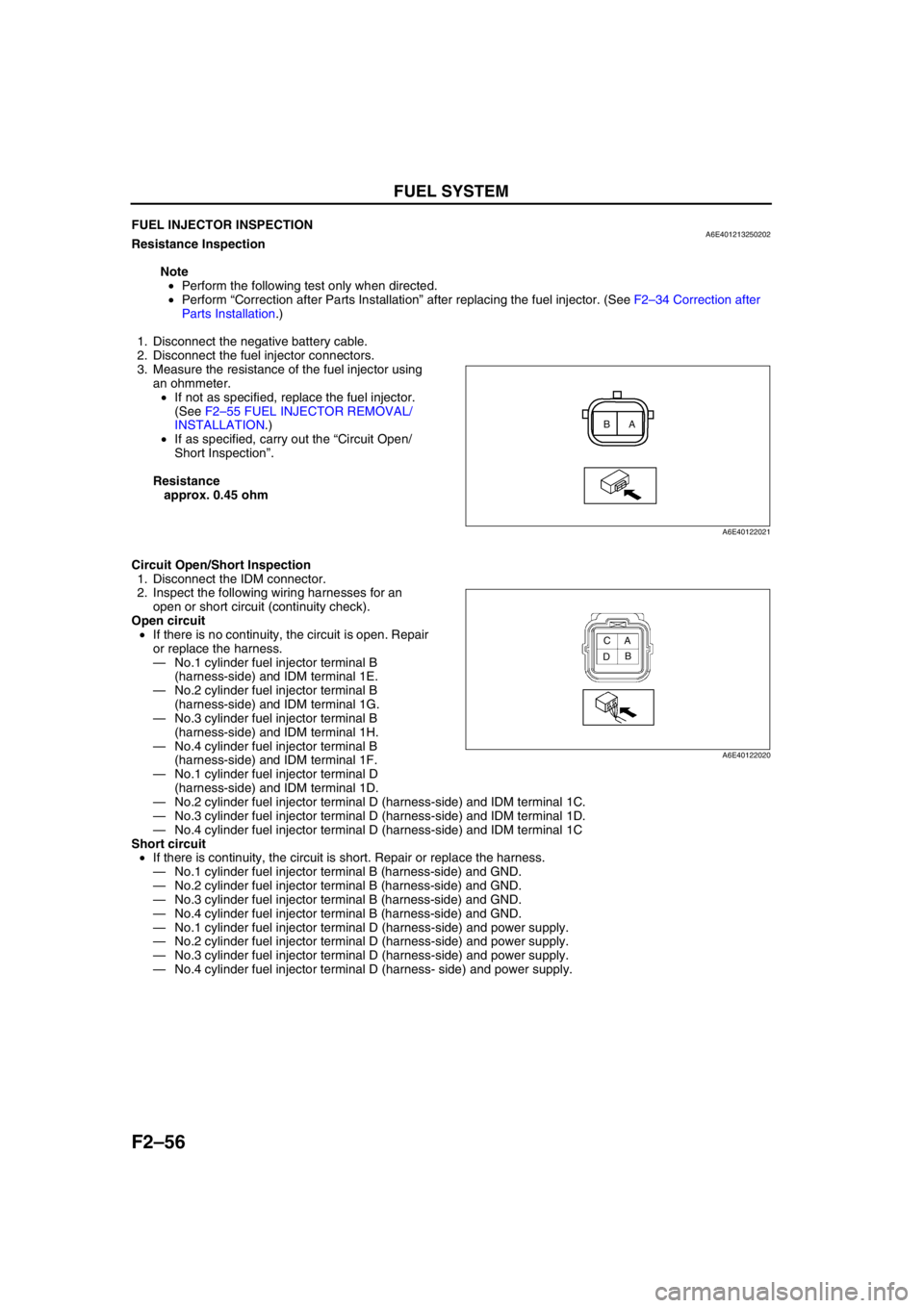
End Of SieFUEL INJECTOR INSPECTIONA6E401213250202Resistance Inspection
Note
•Perform the following test only when directed.
•Perform “Correction after Parts Installation” after replacing the fuel injector. (See F2–34 Correction after
Parts Installation.)
1. Disconnect the negative battery cable.
2. Disconnect the fuel injector connectors.
3. Measure the resistance of the fuel injector using
an ohmmeter.
•If not as specified, replace the fuel injector.
(See F2–55 FUEL INJECTOR REMOVAL/
INSTALLATION.)
•If as specified, carry out the “Circuit Open/
Short Inspection”.
Resistance
approx. 0.45 ohm
Circuit Open/Short Inspection
1. Disconnect the IDM connector.
2. Inspect the following wiring harnesses for an
open or short circuit (continuity check).
Open circuit
•If there is no continuity, the circuit is open. Repair
or replace the harness.
—No.1 cylinder fuel injector terminal B
(harness-side) and IDM terminal 1E.
—No.2 cylinder fuel injector terminal B
(harness-side) and IDM terminal 1G.
—No.3 cylinder fuel injector terminal B
(harness-side) and IDM terminal 1H.
—No.4 cylinder fuel injector terminal B
(harness-side) and IDM terminal 1F.
—No.1 cylinder fuel injector terminal D
(harness-side) and IDM terminal 1D.
—No.2 cylinder fuel injector terminal D (harness-side) and IDM terminal 1C.
—No.3 cylinder fuel injector terminal D (harness-side) and IDM terminal 1D.
—No.4 cylinder fuel injector terminal D (harness-side) and IDM terminal 1C
Short circuit
•If there is continuity, the circuit is short. Repair or replace the harness.
—No.1 cylinder fuel injector terminal B (harness-side) and GND.
—No.2 cylinder fuel injector terminal B (harness-side) and GND.
—No.3 cylinder fuel injector terminal B (harness-side) and GND.
—No.4 cylinder fuel injector terminal B (harness-side) and GND.
—No.1 cylinder fuel injector terminal D (harness-side) and power supply.
—No.2 cylinder fuel injector terminal D (harness-side) and power supply.
—No.3 cylinder fuel injector terminal D (harness-side) and power supply.
—No.4 cylinder fuel injector terminal D (harness- side) and power supply.
End Of Sie
A B
A6E40122021
A
B C
D
A6E40122020
Page 229 of 909

CONTROL SYSTEM
F2–77
F2
FUEL TEMPERATURE SENSOR INSPECTIONA6E404013350201
Note
•Perform the following test only when directed.
Resistance Inspection
1. Disconnect the negative battery cable.
2. Remove the supply pump. (See F2–53 SUPPLY PUMP REMOVAL/INSTALLATION.)
3. Measure the resistance between the fuel
temperature sensor terminals using an
ohmmeter.
•If not as specified, repair the supply pump.
(See F2–54 SUPPLY PUMP INSPECTION.)
Specification
Circuit Open/Short Inspection
1. Inspect for open/short circuit in the following
wiring harnesses.
•If there is open/short circuit, repair or replace wiring harness.
Open circuit
•Signal circuit
—Fuel temperature sensor terminal A and PCM terminal 35
•GND circuit
—Fuel temperature sensor terminal B and PCM terminal 91
Short circuit
•Signal circuit
—Fuel temperature sensor terminal A and PCM terminal 35 to power circuit
—Fuel temperature sensor terminal A and PCM terminal 35 to GND
End Of Sie
Ambient temperature (°C
{°F})Resistance (kilohm)
20 {68} 2.0—3.0
A
B
A6E40702047
Page 231 of 909
CONTROL SYSTEM
F2–79
F2
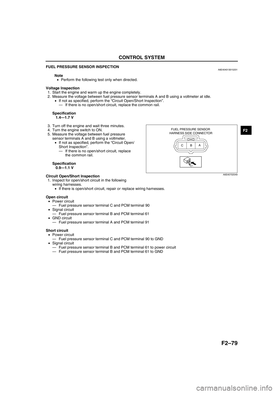
FUEL PRESSURE SENSOR INSPECTIONA6E404013015201
Note
•Perform the following test only when directed.
Voltage Inspection
1. Start the engine and warm up the engine completely.
2. Measure the voltage between fuel pressure sensor terminals A and B using a voltmeter at idle.
•If not as specified, perform the “Circuit Open/Short Inspection”.
—If there is no open/short circuit, replace the common rail.
Specification
1.4—1.7 V
3. Turn off the engine and wait three minutes.
4. Turn the engine switch to ON.
5. Measure the voltage between fuel pressure
sensor terminals A and B using a voltmeter.
•If not as specified, perform the “Circuit Open/
Short Inspection”.
—If there is no open/short circuit, replace
the common rail.
Specification
0.9—1.1 V
CIrcuit Open/Short Inspection
1. Inspect for open/short circuit in the following
wiring harnesses.
•If there is open/short circuit, repair or replace wiring harnesses.
Open circuit
•Power circuit
—Fuel pressure sensor terminal C and PCM terminal 90
•Signal circuit
—Fuel pressure sensor terminal B and PCM terminal 61
•GND circuit
—Fuel pressure sensor terminal A and PCM terminal 91
Short circuit
•Power circuit
—Fuel pressure sensor terminal C and PCM terminal 90 to GND
•Signal circuit
—Fuel pressure sensor terminal B and PCM terminal 61 to power circuit
—Fuel pressure sensor terminal B and PCM terminal 61 to GND
End Of Sie
FUEL PRESSURE SENSOR
HARNESS SIDE CONNECTOR
A
B C
A6E40702049
Page 235 of 909
CONTROL SYSTEM
F2–83
F2
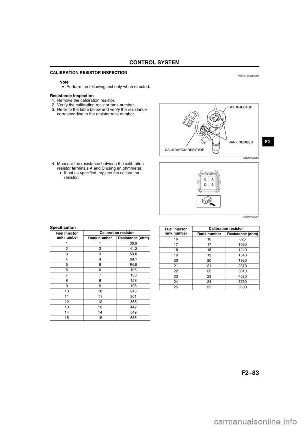
CALIBRATION RESISTOR INSPECTIONA6E404013050201
Note
•Perform the following test only when directed.
Resistance Inspection
1. Remove the calibration resistor.
2. Verify the calibration resistor rank number.
3. Refer to the table below and verify the resistance
corresponding to the resistor rank number.
4. Measure the resistance between the calibration
resistor terminals A and C using an ohmmeter.
•If not as specified, replace the calibration
resistor.
Specification
FUEL INJECTOR
CALIBRATION RESISTORRANK NUMBER
A6E40702056
A
B C
D
A6E40702057
Fuel injector
rank numberCalibration resistor
Rank number Resistance (ohm)
1 1 30.9
2 2 41.2
3 3 53.6
4 4 68.1
5 5 84.5
66105
77130
88158
99196
10 10 243
11 11 301
12 12 365
13 13 442
14 14 549
15 15 665
16 16 825
17 17 1020
18 18 1240
19 19 1540
20 20 1920
21 21 2370
22 22 3010
23 23 4020
24 24 5760
25 25 9530 Fuel injector
rank numberCalibration resistor
Rank number Resistance (ohm)
Page 236 of 909

F2–84
CONTROL SYSTEM
CIrcuit Open/Short Inspection
1. Inspect for open/short circuit in the following wiring harnesses.
•If there is open/short circuit, repair or replace wiring harnesses.
Open circuit
•Signal circuit
—Calibration resistor No.1 terminal A and PCM terminal 37
—Calibration resistor No.2 terminal A and PCM terminal 62
—Calibration resistor No.3 terminal A and PCM terminal 89
—Calibration resistor No.4 terminal A and PCM terminal 11
•GND circuit
—Each calibration resistor terminal C and PCM terminal 91
Short circuit
•Signal circuit
—Calibration resistor No.1 terminal A and PCM terminal 37 to power circuit
—Calibration resistor No.1 terminal A and PCM terminal 37 to GND
—Calibration resistor No.2 terminal A and PCM terminal 62 to power circuit
—Calibration resistor No.2 terminal A and PCM terminal 62 to GND
—Calibration resistor No.3 terminal A and PCM terminal 89 to power circuit
—Calibration resistor No.3 terminal A and PCM terminal 89 to GND
—Calibration resistor No.4 terminal A and PCM terminal 11 to power circuit
—Calibration resistor No.4 terminal A and PCM terminal 11 to GND
End Of Sie
INJECTOR DRIVER MODULE (IDM) INSPECTIONA6E404018701201
Warning
•The IDM outputs high voltage and current for fuel injector driving. Do not inspect the IDM terminal
voltage, as it may cause an electric shock.
Note
•Perform the following test only when directed.
1. If any IDM-related failures are suspected, inspect the following:
•DTCs
•IDM-related harnesses
•Fuel injectors
End Of Sie
Page 239 of 909
ON-BOARD DIAGNOSTIC
F2–87
F2
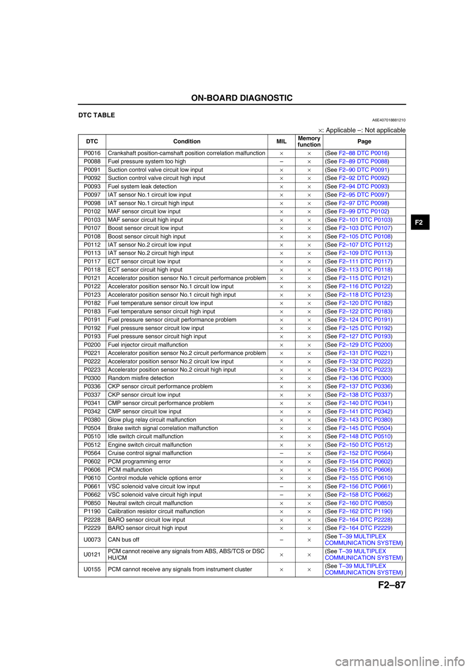
End Of SieDTC TABLEA6E407018881210
×: Applicable –: Not applicable
DTC Condition MILMemory
functionPage
P0016 Crankshaft position-camshaft position correlation malfunction××(See F2–88 DTC P0016)
P0088 Fuel pressure system too high–×(See F2–89 DTC P0088)
P0091 Suction control valve circuit low input××(See F2–90 DTC P0091)
P0092 Suction control valve circuit high input××(See F2–92 DTC P0092)
P0093 Fuel system leak detection××(See F2–94 DTC P0093)
P0097 IAT sensor No.1 circuit low input××(See F2–95 DTC P0097)
P0098 IAT sensor No.1 circuit high input××(See F2–97 DTC P0098)
P0102 MAF sensor circuit low input××(See F2–99 DTC P0102)
P0103 MAF sensor circuit high input××(See F2–101 DTC P0103)
P0107 Boost sensor circuit low input××(See F2–103 DTC P0107)
P0108 Boost sensor circuit high input××(See F2–105 DTC P0108)
P0112 IAT sensor No.2 circuit low input××(See F2–107 DTC P0112)
P0113 IAT sensor No.2 circuit high input××(See F2–109 DTC P0113)
P0117 ECT sensor circuit low input××(See F2–111 DTC P0117)
P0118 ECT sensor circuit high input××(See F2–113 DTC P0118)
P0121 Accelerator position sensor No.1 circuit performance problem××(See F2–115 DTC P0121)
P0122 Accelerator position sensor No.1 circuit low input××(See F2–116 DTC P0122)
P0123 Accelerator position sensor No.1 circuit high input××(See F2–118 DTC P0123)
P0182 Fuel temperature sensor circuit low input××(See F2–120 DTC P0182)
P0183 Fuel temperature sensor circuit high input××(See F2–122 DTC P0183)
P0191 Fuel pressure sensor circuit performance problem××(See F2–124 DTC P0191)
P0192 Fuel pressure sensor circuit low input××(See F2–125 DTC P0192)
P0193 Fuel pressure sensor circuit high input××(See F2–127 DTC P0193)
P0200 Fuel injector circuit malfunction××(See F2–129 DTC P0200)
P0221 Accelerator position sensor No.2 circuit performance problem××(See F2–131 DTC P0221)
P0222 Accelerator position sensor No.2 circuit low input××(See F2–132 DTC P0222)
P0223 Accelerator position sensor No.2 circuit high input××(See F2–134 DTC P0223)
P0300 Random misfire detection××(See F2–136 DTC P0300)
P0336 CKP sensor circuit performance problem××(See F2–137 DTC P0336)
P0337 CKP sensor circuit low input××(See F2–138 DTC P0337)
P0341 CMP sensor circuit performance problem××(See F2–140 DTC P0341)
P0342 CMP sensor circuit low input××(See F2–141 DTC P0342)
P0380 Glow plug relay circuit malfunction××(See F2–143 DTC P0380)
P0504 Brake switch signal correlation malfunction××(See F2–145 DTC P0504)
P0510 Idle switch circuit malfunction××(See F2–148 DTC P0510)
P0512 Engine switch circuit malfunction××(See F2–150 DTC P0512)
P0564 Cruise control signal malfunction–×(See F2–152 DTC P0564)
P0602 PCM programming error××(See F2–154 DTC P0602)
P0606 PCM malfunction××(See F2–155 DTC P0606)
P0610 Control module vehicle options error××(See F2–155 DTC P0610)
P0661 VSC solenoid valve circuit low input–×(See F2–156 DTC P0661)
P0662 VSC solenoid valve circuit high input–×(See F2–158 DTC P0662)
P0850 Neutral switch circuit malfunction××(See F2–160 DTC P0850)
P1190 Calibration resistor circuit malfunction××(See F2–162 DTC P1190)
P2228 BARO sensor circuit low input××(See F2–164 DTC P2228)
P2229 BARO sensor circuit high input××(See F2–164 DTC P2229)
U0073 CAN bus off–×(See T–39 MULTIPLEX
COMMUNICATION SYSTEM)
U0121PCM cannot receive any signals from ABS, ABS/TCS or DSC
HU/CM××(See T–39 MULTIPLEX
COMMUNICATION SYSTEM)
U0155 PCM cannot receive any signals from instrument cluster××(See T–39 MULTIPLEX
COMMUNICATION SYSTEM)
Page 241 of 909
ON-BOARD DIAGNOSTIC
F2–89
F2
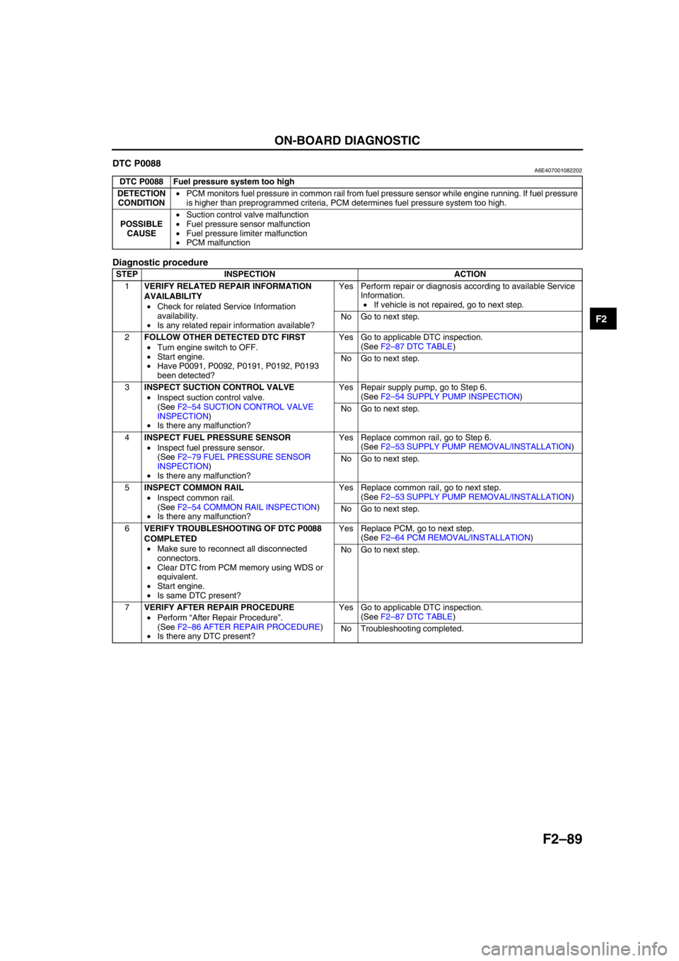
DTC P0088A6E407001082202
Diagnostic procedure
End Of Sie
DTC P0088 Fuel pressure system too high
DETECTION
CONDITION•PCM monitors fuel pressure in common rail from fuel pressure sensor while engine running. If fuel pressure
is higher than preprogrammed criteria, PCM determines fuel pressure system too high.
POSSIBLE
CAUSE•Suction control valve malfunction
•Fuel pressure sensor malfunction
•Fuel pressure limiter malfunction
•PCM malfunction
STEP INSPECTION ACTION
1VERIFY RELATED REPAIR INFORMATION
AVAILABILITY
•Check for related Service Information
availability.
•Is any related repair information available?Yes Perform repair or diagnosis according to available Service
Information.
•If vehicle is not repaired, go to next step.
No Go to next step.
2FOLLOW OTHER DETECTED DTC FIRST
•Turn engine switch to OFF.
•Start engine.
•Have P0091, P0092, P0191, P0192, P0193
been detected?Yes Go to applicable DTC inspection.
(See F2–87 DTC TABLE)
No Go to next step.
3INSPECT SUCTION CONTROL VALVE
•Inspect suction control valve.
(See F2–54 SUCTION CONTROL VALVE
INSPECTION)
•Is there any malfunction?Yes Repair supply pump, go to Step 6.
(See F2–54 SUPPLY PUMP INSPECTION)
No Go to next step.
4INSPECT FUEL PRESSURE SENSOR
•Inspect fuel pressure sensor.
(See F2–79 FUEL PRESSURE SENSOR
INSPECTION)
•Is there any malfunction?Yes Replace common rail, go to Step 6.
(See F2–53 SUPPLY PUMP REMOVAL/INSTALLATION)
No Go to next step.
5INSPECT COMMON RAIL
•Inspect common rail.
(See F2–54 COMMON RAIL INSPECTION)
•Is there any malfunction?Yes Replace common rail, go to next step.
(See F2–53 SUPPLY PUMP REMOVAL/INSTALLATION)
No Go to next step.
6VERIFY TROUBLESHOOTING OF DTC P0088
COMPLETED
•Make sure to reconnect all disconnected
connectors.
•Clear DTC from PCM memory using WDS or
equivalent.
•Start engine.
•Is same DTC present?Yes Replace PCM, go to next step.
(See F2–64 PCM REMOVAL/INSTALLATION)
No Go to next step.
7VERIFY AFTER REPAIR PROCEDURE
•Perform “After Repair Procedure”.
(See F2–86 AFTER REPAIR PROCEDURE)
•Is there any DTC present?Yes Go to applicable DTC inspection.
(See F2–87 DTC TABLE)
No Troubleshooting completed.
Page 246 of 909

F2–94
ON-BOARD DIAGNOSTIC
DTC P0093A6E407001082205
Diagnostic procedure
End Of Sie
DTC P0093 Fuel system leak detection
DETECTION
CONDITION•PCM monitors fuel pressure in common rail from fuel pressure sensor while engine running. If fuel pressure
is lower after fuel injection than preprogrammed criteria, PCM determines fuel system leak detection.
POSSIBLE
CAUSE•Fuel leakage or clogged fuel line
•Suction control valve malfunction
•Fuel pressure sensor malfunction
•Fuel injector malfunction
•PCM malfunction
STEP INSPECTION ACTION
1VERIFY RELATED REPAIR INFORMATION
AVAILABILITY
•Check for related Service Information
availability.
•Is any related repair information available?Yes Perform repair or diagnosis according to available Service
Information.
•If vehicle is not repaired, go to next step.
No Go to next step.
2FOLLOW OTHER DETECTED DTC FIRST
•Turn engine switch to OFF.
•Start engine.
•Have P0192, P0193, P1190 been detected?Yes Go to applicable DTC inspection.
(See F2–87 DTC TABLE)
No Go to next step.
3INSPECT FUEL LINE
•Turn engine switch to OFF.
•Inspect for fuel leakage or clogs in following
fuel lines for each cylinder:
—Supply pump and Common rail.
—Common rail and fuel injector.
• Is there any malfunction?Yes Repair or replace suspected fuel line, go to Step 7.
No Go to next step.
4INSPECT SUCTION CONTROL VALVE
•Inspect suction control valve.
(See F2–54 SUCTION CONTROL VALVE
INSPECTION)
•Is there any malfunction?Yes Repair supply pump, go to Step 7.
(See F2–54 SUPPLY PUMP INSPECTION)
No Go to next step.
5INSPECT FUEL PRESSURE SENSOR
•Inspect fuel pressure sensor.
(See F2–79 FUEL PRESSURE SENSOR
INSPECTION)
•Is there any malfunction?Yes Replace common rail, go to Step 7.
(See F2–53 SUPPLY PUMP REMOVAL/INSTALLATION)
No Go to next step.
6INSPECT FUEL INJECTOR
•Inspect fuel injector.
(See F2–56 FUEL INJECTOR INSPECTION)
•Is there any malfunction?Yes Replace fuel injector, go to next step.
(See F2–55 FUEL INJECTOR REMOVAL/INSTALLATION)
No Go to next step.
7VERIFY TROUBLESHOOTING OF DTC P0093
COMPLETED
•Make sure to reconnect all disconnected
connectors.
•Clear DTC from PCM memory using WDS or
equivalent.
•Start engine.
•Is same DTC present?Yes Replace PCM, go to next step.
(See F2–64 PCM REMOVAL/INSTALLATION)
No Go to next step.
8VERIFY AFTER REPAIR PROCEDURE
•Perform “After Repair Procedure”.
(See F2–86 AFTER REPAIR PROCEDURE)
•Is there any DTC present?Yes Go to applicable DTC inspection.
(See F2–87 DTC TABLE)
No Troubleshooting completed.
Page 272 of 909

F2–120
ON-BOARD DIAGNOSTIC
DTC P0182A6E407001082219
Diagnostic procedure
DTC P0182 Fuel temperature sensor circuit low input
DETECTION
CONDITION•PCM monitors input voltage from fuel temperature sensor while engine is running. If input voltage from fuel
temperature sensor is below 0.1 V, PCM determines fuel temperature sensor circuit low input.
POSSIBLE
CAUSE•Fuel temperature sensor malfunction
•Connector or terminal malfunction
•Short to GND in wiring between fuel temperature sensor terminal A and PCM terminal 35
•Fuel temperature sensor signal and GND circuits short each other
•PCM malfunction
FUEL TEMPERATURE SENSOR
462
5
4362A
B35
91PCM
BA
9135 FUEL TEMPERATURE SENSOR
HARNESS SIDE CONNECTORPCM
HARNESS SIDE CONNECTOR
STEP INSPECTION ACTION
1VERIFY RELATED REPAIR INFORMATION
AVAILABILITY
•Check for related Service Information
availability.
•Is any related repair information available?Yes Perform repair or diagnosis according to available Service
Information.
•If vehicle is not repaired, go to next step.
No Go to next step.