service MAZDA 6 2002 Workshop Manual Suplement
[x] Cancel search | Manufacturer: MAZDA, Model Year: 2002, Model line: 6, Model: MAZDA 6 2002Pages: 909, PDF Size: 17.16 MB
Page 418 of 909

OUTLINE
K2–3
K2
FEATURESA6E570201030201ATX
Improved marketability
•New JA5AX-EL automatic transaxle for 4WD is used with on L3 engine.
Improved shift quality
•Five speed automatic transaxle has been adopted.
•The feedback control system has been adopted.
•The centrifugal balance clutch chambers have been adopted.
•A plate-type clutch pack replaces the band brake in the 2-4 brake.
High efficiency, compactness, and light weight
•Miniature trochoid gear type oil pump with torque converter direct drive has been adopted.
End Of Sie
SPECIFICATIONSA6E570201030202
OUTLINE
ItemNew Mazda6 (GY) Current MPV (LW)
–For General
(R.H.D.)
specs.Except for
General
(R.H.D.)
specs.
Transaxle type JA5AX-EL JA5A-EL
Gear ratio1GR 3.801
2GR 2.131
3GR 1.364
4GR 0.935
5GR (O/D) 0.685
Reverse 2.970
Final gear ratio 3.491 3.290 3.491
ATFType
ATF M-III or equivalent (e.g. Dexron
®III)
Capacity (approximate quantity)
(L {US qt, Imp qt})8.3 {8.8, 7.3} 9.7 {10.3, 8.5}
Torque converter stall torque ratio 1.86:1
Hydraulic system (Number of
drive/driven plates)Low clutch 6/6 7/7
2-4 brake 3/4
High clutch 5/5
Direct clutch 3/5 4/4
Reverse clutch 2/2
Low and reverse brake 6/5
Band servo (mm {in})Reduction accumulator piston outer
dia./reduction band servo piston
outer dia.49.66/57.64
Number of front planetary gear
teethRing gear 74
Sun gear 34
Pinion gear 20
Number of rear planetary gear
teethRing gear 75
Sun gear 42
Pinion gear 17
Number of reduction planetary
gear teethRing gear 85
Sun gear 31
Pinion gear 27
Number of output gear teeth 41
Number of idler gear teeth 47
Number of reduction gear teeth 22 23 22
Number of ring gear teeth 67 66 67
Transfer oilTypeSAE 80W-90
API Service GL-5–
Capacity (approximate quantity)
(L {US qt, Imp qt})0.62 {0.66, 0.55}–
Page 514 of 909
AUTOMATIC TRANSAXLE
K2–99
K2
AUTOMATIC TRANSAXLE AND TRANSFER REMOVAL/INSTALLATIONA6E5714190902011. Disconnect the negative battery cable.
2. Remove the battery and battery tray.
3. Remove the aircleaner component. (See Sectin F.)
4. Remove the front tires and splash shield.
5. Remove the under cover.
6. Separate the steering shaft and steering hose. (See N–13 STEERING GEAR AND LINKAGE (4WD)
REMOVAL/INSTALLATION.)
7. Remove the front auto leveling sensor. (See Section T.)
8. Drain the ATF. (See K2–80 AUTOMATIC TRANSAXLE FLUID (ATF) REPLACEMENT.)
Warning
•Improperly jacking a transaxle is dangerous. It can slip off the jack and may cause serious injury.
Caution
•To prevent the torque converter and transaxle from separating, remove the transaxle without
tilting it toward the torque converter.
9. Remove in the order shown in the figure.
10. Install in the reverse order of removal.
11. Adjust the headlight zeroset. (See Section T.)
12. Add ATF to the specified level. (See K2–80 AUTOMATIC TRANSAXLE FLUID (ATF) REPLACEMENT.)
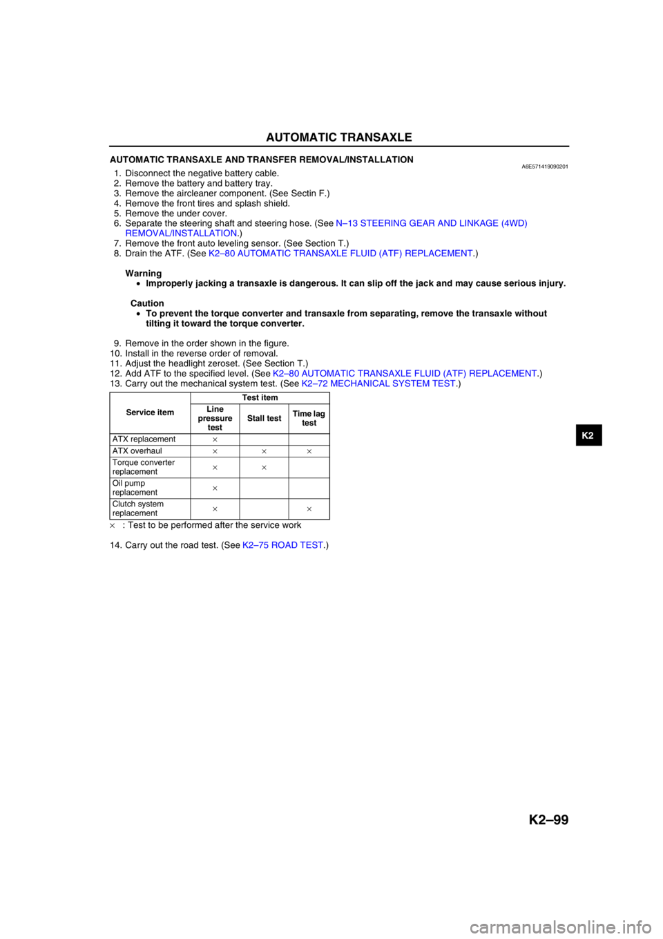
13. Carry out the mechanical system test. (See K2–72 MECHANICAL SYSTEM TEST.)
×: Test to be performed after the service work
14. Carry out the road test. (See K2–75 ROAD TEST.)
Service itemTest item
Line
pressure
testStall testTime lag
test
ATX replacement×
ATX overhaul×××
Torque converter
replacement××
Oil pump
replacement×
Clutch system
replacement××
Page 523 of 909
K2–108
AUTOMATIC TRANSAXLE
OIL COOLER REMOVAL/INSTALLATIONA6E5714199002031. Disconnect the negative battery cable.
2. Drain the ATF into a container. (See K2–80 AUTOMATIC TRANSAXLE FLUID (ATF) REPLACEMENT.)
3. Remove the radiator. (See Section E.)
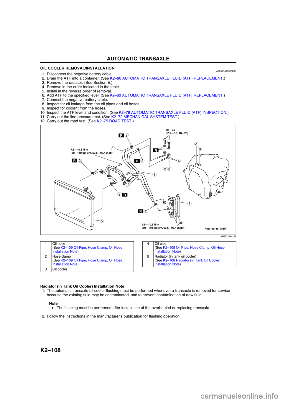
4. Remove in the order indicated in the table.
5. Install in the reverse order of removal.
6. Add ATF to the specified level. (See K2–80 AUTOMATIC TRANSAXLE FLUID (ATF) REPLACEMENT.)
7. Connect the negative battery cable.
8. Inspect for oil leakage from the oil pipes and oil hoses.
9. Inspect for coolant from the hoses.
10. Inspect the ATF level and condition. (See K2–78 AUTOMATIC TRANSAXLE FLUID (ATF) INSPECTION.)
11. Carry out the line pressure test. (See K2–72 MECHANICAL SYSTEM TEST.)
12. Carry out the road test. (See K2–75 ROAD TEST.)
.
Radiator (In Tank Oil Cooler) Installation Note
1. The automatic transaxle oil cooler flushing must be performed whenever a transaxle is removed for service
because the existing fluid may be contaminated, and to prevent contamination of new fluid.
Note
• The flushing must be performed after installation of the overhauled or replacing transaxle.
2. Follow the instructions in the manufacturer’s publication for flushing operation.
R
R
1
2
1
3
4
2
R2
R2
R
7.8—10.8 N·m
{80—110 kgf·cm, 69.5—95.4 in·lbf} 7.8—10.8 N·m
{80—110 kgf·cm, 69.5—95.4 in·lbf}24—35
{2.5—3.5, 18—26}
2
5
AB
A
B
N·m {kgf·m, ft·lbf}
R
A6E5714W146
1Oil hose
(See K2–109 Oil Pipe, Hose Clamp, Oil Hose
Installation Note)
2 Hose clamp
(See K2–109 Oil Pipe, Hose Clamp, Oil Hose
Installation Note)
3Oil cooler4 Oil pipe
(See K2–109 Oil Pipe, Hose Clamp, Oil Hose
Installation Note)
5 Radiator (in tank oil cooler)
(See K2–108 Radiator (In Tank Oil Cooler)
Installation Note)
Page 529 of 909
K2–114
TRANSFER
TRANSFER OIL INSPECTIONA6E5718170012011. Park the vehicle on level ground.
2. Remove the PTO heat shield.
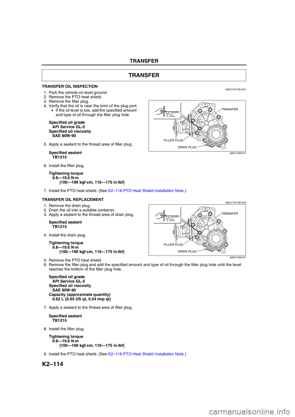
3. Remove the filler plug.
4. Verify that the oil is near the brim of the plug port.
•If the oil level is low, add the specified amount
and type of oil through the filler plug hole.
Specified oil grade
API Service GL-5
Specified oil viscosity
SAE 80W-90
5. Apply a sealant to the thread area of filler plug.
Specified sealant
TB1215
6. Install the filler plug.
Tightening torque
9.8—19.6 N·m
{100—199 kgf·cm, 116—175 in·lbf}
7. Install the PTO heat shield. (See K2–116 PTO Heat Shield Installation Note.)
End Of Sie
TRANSFER OIL REPLACEMENTA6E5718170012021. Remove the drain plug.
2. Drain the oil into a suitable container.
3. Apply a sealant to the thread area of drain plug.
Specified sealant
TB1215
4. Install the drain plug.
Tightening torque
9.8—19.6 N·m
{100—199 kgf·cm, 116—175 in·lbf}
5. Remove the PTO heat shield.
6. Remove the filler plug and add the specified amount and type of oil through the filler plug hole until the level
reaches the bottom of the filler plug hole.
Specified oil grade
API Service GL-5
Specified oil viscosity
SAE 80W-90
Capacity (approximate quantity)
0.62 L {0.65 US qt, 0.54 lmp qt}
7. Apply a sealant to the thread area of filler plug.
Specified sealant
TB1215
8. Install the filler plug.
Tightening torque
9.8—19.6 N·m
{100—199 kgf·cm, 116—175 in·lbf}
9. Install the PTO heat shield. (See K2–116 PTO Heat Shield Installation Note.)
TRANSFER
TRANSFER
FILLER PLUG
DRAIN PLUG
A6E5718W101
TRANSFER
FILLER PLUG
DRAIN PLUG
A6E5718W101
Page 542 of 909
ON-BOARD DIAGNOSTIC
K2–127
K2
DTC P0705A6E577018901205
Diagnostic procedure
DTC P0705 Transaxle range (TR) switch circuit malfunction (short circuit)
DETECTION
CONDITION•Two or more range signals are input from TR switch for 5 seconds or more.
Diagnostic support note:
•This is a continuous monitor (CCM).
•MIL illuminates if TCM detects the above malfunction conditions in two consecutive drive cycles.
•PENDING CODE is available above malfunction condition during first drive cycle.
•FREEZE FRAME DATA is available.
•AT warning light indication.
•DTC is stored in TCM memory.
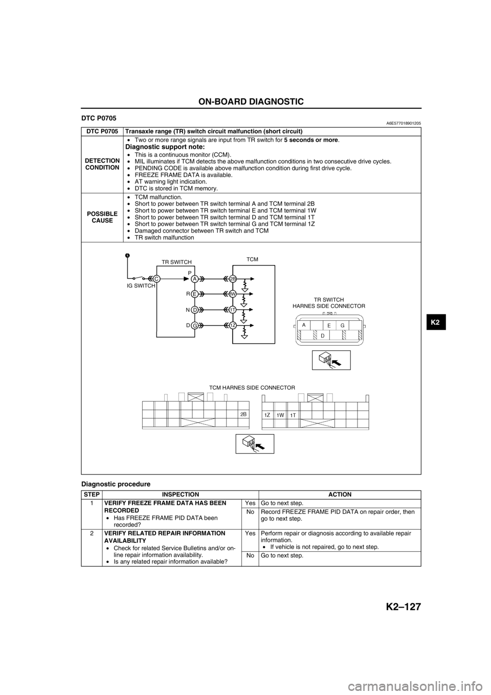
POSSIBLE
CAUSE•TCM malfunction.
•Short to power between TR switch terminal A and TCM terminal 2B
•Short to power between TR switch terminal E and TCM terminal 1W
•Short to power between TR switch terminal D and TCM terminal 1T
•Short to power between TR switch terminal G and TCM terminal 1Z
•Damaged connector between TR switch and TCM
•TR switch malfunction
STEP INSPECTION ACTION
1VERIFY FREEZE FRAME DATA HAS BEEN
RECORDED
•Has FREEZE FRAME PID DATA been
recorded?Yes Go to next step.
No Record FREEZE FRAME PID DATA on repair order, then
go to next step.
2VERIFY RELATED REPAIR INFORMATION
AVAILABILITY
•Check for related Service Bulletins and/or on-
line repair information availability.
•Is any related repair information available?Yes Perform repair or diagnosis according to available repair
information.
•If vehicle is not repaired, go to next step.
No Go to next step.
TR SWITCHTCM
TR SWITCH
HARNES SIDE CONNECTOR
TCM HARNES SIDE CONNECTOR IG SWITCHP
A
C
2B
1W
1T
1Z
E
D
G R
N
D
Page 545 of 909
K2–130
ON-BOARD DIAGNOSTIC
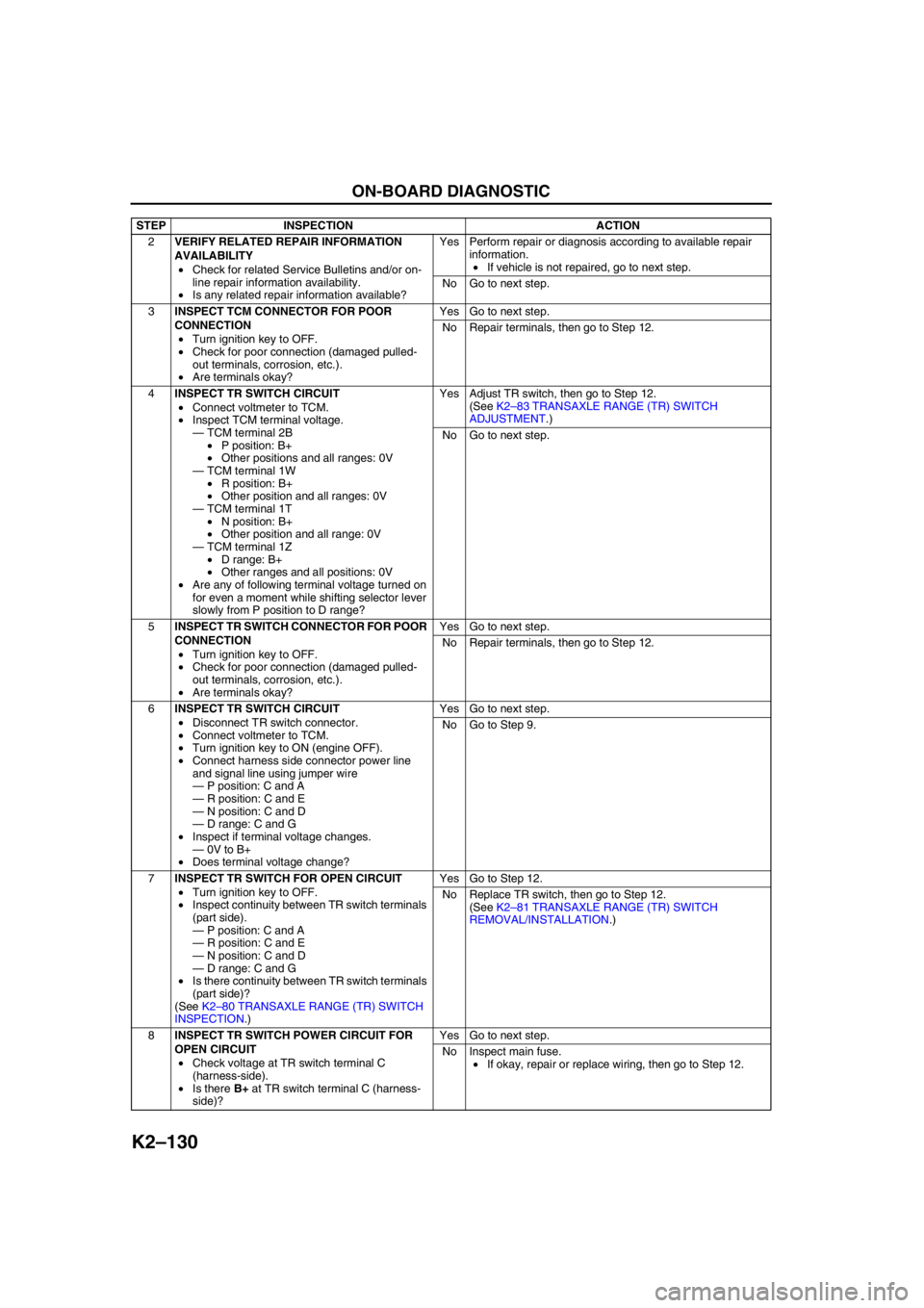
2VERIFY RELATED REPAIR INFORMATION
AVAILABILITY
•Check for related Service Bulletins and/or on-
line repair information availability.
•Is any related repair information available?Yes Perform repair or diagnosis according to available repair
information.
•If vehicle is not repaired, go to next step.
No Go to next step.
3INSPECT TCM CONNECTOR FOR POOR
CONNECTION
•Turn ignition key to OFF.
•Check for poor connection (damaged pulled-
out terminals, corrosion, etc.).
•Are terminals okay?Yes Go to next step.
No Repair terminals, then go to Step 12.
4INSPECT TR SWITCH CIRCUIT
•Connect voltmeter to TCM.
•Inspect TCM terminal voltage.
—TCM terminal 2B
•P position: B+
•Other positions and all ranges: 0V
—TCM terminal 1W
•R position: B+
•Other position and all ranges: 0V
—TCM terminal 1T
•N position: B+
•Other position and all range: 0V
—TCM terminal 1Z
•D range: B+
•Other ranges and all positions: 0V
•Are any of following terminal voltage turned on
for even a moment while shifting selector lever
slowly from P position to D range?Yes Adjust TR switch, then go to Step 12.
(See K2–83 TRANSAXLE RANGE (TR) SWITCH
ADJUSTMENT.)
No Go to next step.
5INSPECT TR SWITCH CONNECTOR FOR POOR
CONNECTION
•Turn ignition key to OFF.
•Check for poor connection (damaged pulled-
out terminals, corrosion, etc.).
•Are terminals okay?Yes Go to next step.
No Repair terminals, then go to Step 12.
6INSPECT TR SWITCH CIRCUIT
•Disconnect TR switch connector.
•Connect voltmeter to TCM.
•Turn ignition key to ON (engine OFF).
•Connect harness side connector power line
and signal line using jumper wire
—P position: C and A
—R position: C and E
—N position: C and D
—D range: C and G
•Inspect if terminal voltage changes.
—0V to B+
•Does terminal voltage change?Yes Go to next step.
No Go to Step 9.
7INSPECT TR SWITCH FOR OPEN CIRCUIT
•Turn ignition key to OFF.
•Inspect continuity between TR switch terminals
(part side).
—P position: C and A
—R position: C and E
—N position: C and D
—D range: C and G
•Is there continuity between TR switch terminals
(part side)?
(See K2–80 TRANSAXLE RANGE (TR) SWITCH
INSPECTION.)Yes Go to Step 12.
No Replace TR switch, then go to Step 12.
(See K2–81 TRANSAXLE RANGE (TR) SWITCH
REMOVAL/INSTALLATION.)
8INSPECT TR SWITCH POWER CIRCUIT FOR
OPEN CIRCUIT
•Check voltage at TR switch terminal C
(harness-side).
•Is there B+ at TR switch terminal C (harness-
side)?Yes Go to next step.
No Inspect main fuse.
•If okay, repair or replace wiring, then go to Step 12. STEP INSPECTION ACTION
Page 547 of 909
K2–132
ON-BOARD DIAGNOSTIC
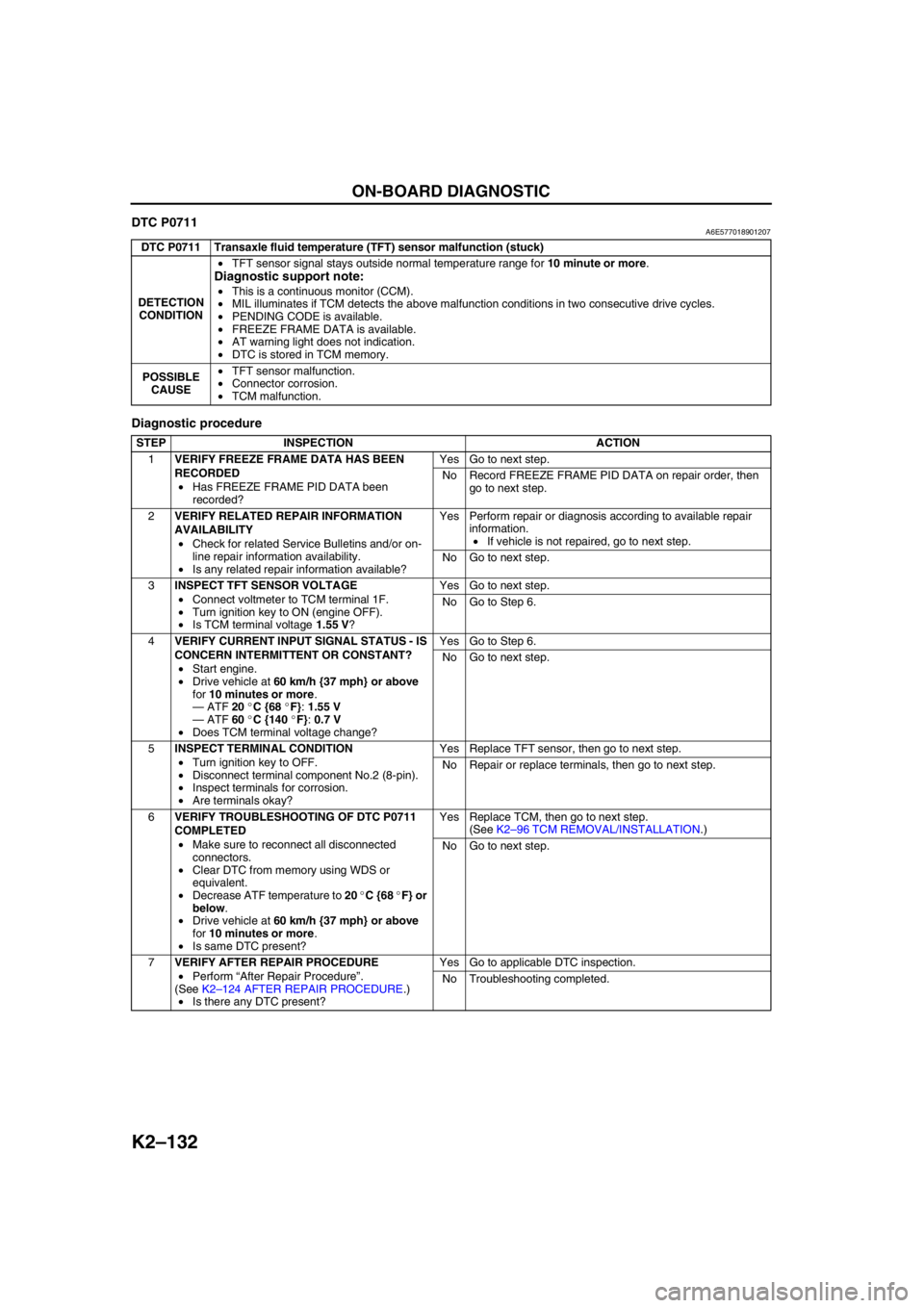
DTC P0711A6E577018901207
Diagnostic procedure
End Of Sie
DTC P0711 Transaxle fluid temperature (TFT) sensor malfunction (stuck)
DETECTION
CONDITION•TFT sensor signal stays outside normal temperature range for 10 minute or more.
Diagnostic support note:
•This is a continuous monitor (CCM).
•MIL illuminates if TCM detects the above malfunction conditions in two consecutive drive cycles.
•PENDING CODE is available.
•FREEZE FRAME DATA is available.
•AT warning light does not indication.
•DTC is stored in TCM memory.
POSSIBLE
CAUSE•TFT sensor malfunction.
•Connector corrosion.
•TCM malfunction.
STEP INSPECTION ACTION
1VERIFY FREEZE FRAME DATA HAS BEEN
RECORDED
•Has FREEZE FRAME PID DATA been
recorded?Yes Go to next step.
No Record FREEZE FRAME PID DATA on repair order, then
go to next step.
2VERIFY RELATED REPAIR INFORMATION
AVAILABILITY
•Check for related Service Bulletins and/or on-
line repair information availability.
•Is any related repair information available?Yes Perform repair or diagnosis according to available repair
information.
•If vehicle is not repaired, go to next step.
No Go to next step.
3INSPECT TFT SENSOR VOLTAGE
•Connect voltmeter to TCM terminal 1F.
•Turn ignition key to ON (engine OFF).
•Is TCM terminal voltage 1.55 V?Yes Go to next step.
No Go to Step 6.
4VERIFY CURRENT INPUT SIGNAL STATUS - IS
CONCERN INTERMITTENT OR CONSTANT?
•Start engine.
•Drive vehicle at 60 km/h {37 mph} or above
for 10 minutes or more.
—ATF 20 °C {68 °F}: 1.55 V
—ATF 60 °C {140 °F}: 0.7 V
•Does TCM terminal voltage change?Yes Go to Step 6.
No Go to next step.
5INSPECT TERMINAL CONDITION
•Turn ignition key to OFF.
•Disconnect terminal component No.2 (8-pin).
•Inspect terminals for corrosion.
•Are terminals okay?Yes Replace TFT sensor, then go to next step.
No Repair or replace terminals, then go to next step.
6VERIFY TROUBLESHOOTING OF DTC P0711
COMPLETED
•Make sure to reconnect all disconnected
connectors.
•Clear DTC from memory using WDS or
equivalent.
•Decrease ATF temperature to 20 °C {68 °F} or
below.
•Drive vehicle at 60 km/h {37 mph} or above
for 10 minutes or more.
•Is same DTC present?Yes Replace TCM, then go to next step.
(See K2–96 TCM REMOVAL/INSTALLATION.)
No Go to next step.
7VERIFY AFTER REPAIR PROCEDURE
•Perform “After Repair Procedure”.
(See K2–124 AFTER REPAIR PROCEDURE.)
•Is there any DTC present?Yes Go to applicable DTC inspection.
No Troubleshooting completed.
Page 548 of 909
ON-BOARD DIAGNOSTIC
K2–133
K2
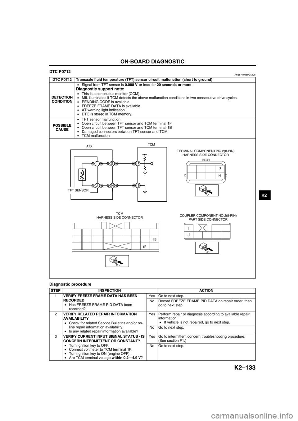
DTC P0712A6E577018901208
Diagnostic procedure
DTC P0712 Transaxle fluid temperature (TFT) sensor circuit malfunction (short to ground)
DETECTION
CONDITION•Signal from TFT sensor is 0.088 V or less for 20 seconds or more.
Diagnostic support note:
•This is a continuous monitor (CCM).
•MIL illuminates if TCM detects the above malfunction conditions in two consecutive drive cycles.
•PENDING CODE is available.
•FREEZE FRAME DATA is available.
•AT warning light indication.
•DTC is stored in TCM memory.
POSSIBLE
CAUSE•TFT sensor malfunction.
•Open circuit between TFT sensor and TCM terminal 1F
•Open circuit between TFT sensor and TCM terminal 1B
•Damaged connectors between TFT sensor and TCM
•TCM malfunction
STEP INSPECTION ACTION
1VERIFY FREEZE FRAME DATA HAS BEEN
RECORDED
•Has FREEZE FRAME PID DATA been
recorded?Yes Go to next step.
No Record FREEZE FRAME PID DATA on repair order, then
go to next step.
2VERIFY RELATED REPAIR INFORMATION
AVAILABILITY
•Check for related Service Bulletins and/or on-
line repair information availability.
•Is any related repair information available?Yes Perform repair or diagnosis according to available repair
information.
•If vehicle is not repaired, go to next step.
No Go to next step.
3VERIFY CURRENT INPUT SIGNAL STATUS - IS
CONCERN INTERMITTENT OR CONSTANT?
•Turn ignition key to OFF.
•Connect voltmeter to TCM terminal 1F.
•Turn ignition key to ON (engine OFF).
•Are TCM terminal voltage within 0.2—4.9 V?Yes Go to intermittent concern troubleshooting procedure.
(See section F1.)
No Go to next step.
AT XTCM
IG1F
1B
JH
TFT SENSOR
TCM
HARNESS SIDE CONNECTORTERMINAL COMPONENT NO.2(8-PIN)
HARNESS SIDE CONNECTOR
COUPLER COMPONENT NO.2(8-PIN)
PART SIDE CONNECTOR
Page 550 of 909
ON-BOARD DIAGNOSTIC
K2–135
K2
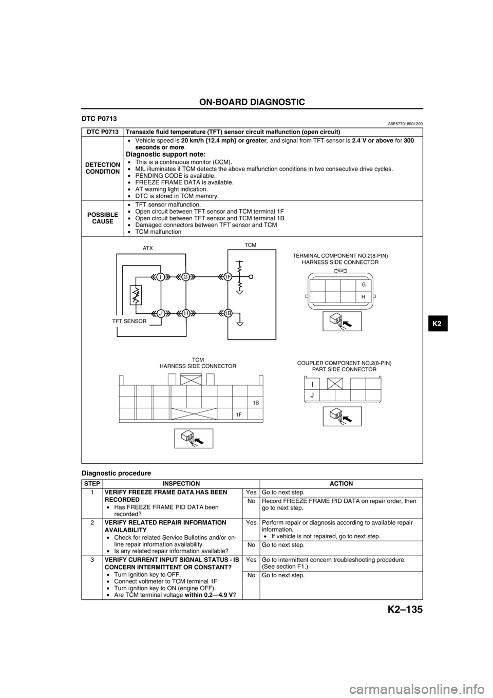
DTC P0713A6E577018901209
Diagnostic procedure
DTC P0713 Transaxle fluid temperature (TFT) sensor circuit malfunction (open circuit)
DETECTION
CONDITION•Vehicle speed is 20 km/h {12.4 mph} or greater, and signal from TFT sensor is 2.4 V or above for 300
seconds or more.
Diagnostic support note:
•This is a continuous monitor (CCM).
•MIL illuminates if TCM detects the above malfunction conditions in two consecutive drive cycles.
•PENDING CODE is available.
•FREEZE FRAME DATA is available.
•AT warning light indication.
•DTC is stored in TCM memory.
POSSIBLE
CAUSE•TFT sensor malfunction.
•Open circuit between TFT sensor and TCM terminal 1F
•Open circuit between TFT sensor and TCM terminal 1B
•Damaged connectors between TFT sensor and TCM
•TCM malfunction
STEP INSPECTION ACTION
1VERIFY FREEZE FRAME DATA HAS BEEN
RECORDED
•Has FREEZE FRAME PID DATA been
recorded?Yes Go to next step.
No Record FREEZE FRAME PID DATA on repair order, then
go to next step.
2VERIFY RELATED REPAIR INFORMATION
AVAILABILITY
•Check for related Service Bulletins and/or on-
line repair information availability.
•Is any related repair information available?Yes Perform repair or diagnosis according to available repair
information.
•If vehicle is not repaired, go to next step.
No Go to next step.
3VERIFY CURRENT INPUT SIGNAL STATUS - IS
CONCERN INTERMITTENT OR CONSTANT?
•Turn ignition key to OFF.
•Connect voltmeter to TCM terminal 1F
•Turn ignition key to ON (engine OFF).
•Are TCM terminal voltage within 0.2—4.9 V?Yes Go to intermittent concern troubleshooting procedure.
(See section F1.)
No Go to next step.
AT XTCM
IG1F
1B
JH
TFT SENSOR
TCM
HARNESS SIDE CONNECTORTERMINAL COMPONENT NO.2(8-PIN)
HARNESS SIDE CONNECTOR
COUPLER COMPONENT NO.2(8-PIN)
PART SIDE CONNECTOR
Page 553 of 909

K2–138
ON-BOARD DIAGNOSTIC
Diagnostic procedure
STEP INSPECTION ACTION
1VERIFY FREEZE FRAME DATA HAS BEEN
RECORDED
•Has FREEZE FRAME PID DATA been
recorded?Yes Go to next step.
No Record FREEZE FRAME PID DATA on repair order, then
go to next step.
2VERIFY RELATED REPAIR INFORMATION
AVAILABILITY
•Check for related Service Bulletins and/or on-
line repair information availability.
•Is any related repair information available?Yes Perform repair or diagnosis according to available repair
information.
•If vehicle is not repaired, go to next step.
No Go to next step.
3INSPECT TERMINAL COMPONENT NO.2 (8-
PIN) CONNECTOR FOR POOR CONNECTION
•Turn ignition key to OFF.
•Disconnect terminal component No.2 (8-pin)
connector.
•Check for poor connection (damaged, pulled-
out terminals, corrosion, etc.).
•Are terminals okay?Yes Go to next step.
No Repair or replace terminals, then go to Step 12.
4INSPECT INPUT/TURBINE SPEED SENSOR
RESISTANCE
•Measure resistance between terminal
component No.2 (8-pin) (transaxle case side).
•Is resistance within 513—627 ohms between
terminal component No.2 (8-pin) terminal E
and F (transaxle case side)?Yes Go to next step.
No Go to Step 8
5INSPECT TCM CONNECTOR FOR POOR
CONNECTION
•Disconnect TCM connector.
•Check for poor connection (damaged, pulled-
out terminals, corrosion, etc.).
•Are terminals okay?Yes Go to next step.
No Repair terminals, then go to Step 12.
6INSPECT TERMINAL COMPONENT NO.2 (8-
PIN) CIRCUIT FOR OPEN
•Check terminal component No.2 (8-pin)
terminals (harness-side) and TCM terminals
(harness-side).
—F and 2F
—E and 1N
•Is there continuity?Yes Go to next step.
No Repair or replace harness, then go to Step 12.
7INSPECT TERMINAL COMPONENT NO.2 (8-
PIN) CIRCUIT FOR SHORT TO GROUND
•Check terminal component No.2 (8-pin)
terminal (harness-side) and body ground.
—F and body ground
—E and body ground
•Is there any continuity?Yes Repair or replace harness, then go to Step 12.
No Go to Step 12.
8INSPECT COUPLER COMPONENT (8-PIN)
CONNECTOR FOR POOR CONNECTION
•Disassemble the control valve body cover.
•Disconnect coupler component (8-pin)
connector.
•Check for poor connection (damaged, pulled-
out terminals, corrosion, etc.).
•Are terminals okay?Yes Go to next step.
No Repair terminals, then go to Step 12.
9INSPECT INPUT/TURBINE SPEED SENSOR
RESISTANCE
•Measure resistance between coupler
component (8-pin) (transaxle case side).
•Is resistance within 513—527 ohms between
coupler component (8-pin) terminal B and A
(part side)?Yes Repair or replace terminal component, then go to Step 12.
No Go to next step.