immobilizer MAZDA 6 2002 Suplement User Guide
[x] Cancel search | Manufacturer: MAZDA, Model Year: 2002, Model line: 6, Model: MAZDA 6 2002Pages: 909, PDF Size: 17.16 MB
Page 168 of 909

F2–16
EMISSION SYSTEM, CONTROL SYSTEM
End Of SieWARM UP OXIDATION CATALYTIC CONVERTER DESCRIPTIONA6E401601007203•The warm up oxidation catalytic converter capacity has been increased to 1,920 ml {1,920 cc, 117 cu in} in
order to improve emission performance.
End Of Sie
OUTLINEA6E404018881201•The control system is essentially carried over from that of the current MPV (LW) MZR-CD (RF Turbo) engine
models. (See MPV Workshop Manual Supplement 1737-1*-02C.)
Input Device
×:Applicable –: Not applicable
CONTROL SYSTEM
ItemMazda6
(GG, GY)Current
MPV (LW)
Remark for new model
MZR-CD (RF Turbo)
Battery×Same function as MPV (LW) MZR-CD (RF Turbo) engine model
Starter (starter signal)×Same function as MPV (LW) MZR-CD (RF Turbo) engine model
Starter relay×–Newly adopted
Clutch switch×Same function as MPV (LW) MZR-CD (RF Turbo) engine model
Neutral switch×Same function as MPV (LW) MZR-CD (RF Turbo) engine model
Brake switch×Same function as Mazda6 (GG) L series engine model
Idle switch×Same function as MPV (LW) MZR-CD (RF Turbo) engine model
A/C switch×Same function as MPV (LW) MZR-CD (RF Turbo) engine model
Refrigerant pressure switch×Same function as 626 (GF, GW) RF Turbo engine model
Cruise control switch×Same function as Mazda6 (GG) L series engine model
Accelerator position sensor×Same function as MPV (LW) MZR-CD (RF Turbo) engine model
MAF/IAT sensor×Same function as MPV (LW) MZR-CD (RF Turbo) engine model
IAT sensor No.2×Same function as MPV (LW) MZR-CD (RF Turbo) engine model
ECT sensor×Same function as MPV (LW) MZR-CD (RF Turbo) engine model
Fuel temperature sensor×Same function as MPV (LW) MZR-CD (RF Turbo) engine model
BARO sensor (integrated in PCM)×Same function as MPV (LW) MZR-CD (RF Turbo) engine model
Boost sensor×Same function as MPV (LW) MZR-CD (RF Turbo) engine model
Fuel pressure sensor×Same function as MPV (LW) MZR-CD (RF Turbo) engine model
CMP sensor×Same function as MPV (LW) MZR-CD (RF Turbo) engine model
CKP sensor×Same function as MPV (LW) MZR-CD (RF Turbo) engine model
VSS×Vehicle speed signal is received by CAN
Calibration resistor×Same function as MPV (LW) MZR-CD (RF Turbo) engine model
Immobilizer unit (integrated in
PCM)×Immobilizer unit equipped into PCM
Page 169 of 909

CONTROL SYSTEM
F2–17
F2
Output Device
×:Applicable –: Not applicable
Control System
×:Applicable –: Not applicable
End Of Sie
ItemMazda6
(GG, GY)Current
MPV (LW)
Remark for new model
MZR-CD (RF Turbo)
Suction control valve×Same function as MPV (LW) MZR-CD (RF Turbo) engine model
IDM×Same function as MPV (LW) MZR-CD (RF Turbo) engine model
VSC solenoid valve×Same function as MPV (LW) MZR-CD (RF Turbo) engine model
VBC solenoid valve×Same function as MPV (LW) MZR-CD (RF Turbo) engine model
EGR control solenoid valve×Same function as MPV (LW) MZR-CD (RF Turbo) engine model
EGR solenoid valve (vacuum)×Same function as MPV (LW) MZR-CD (RF Turbo) engine model
EGR solenoid valve (vent)×Same function as MPV (LW) MZR-CD (RF Turbo) engine model
Intake shutter solenoid valve (half)×Same function as MPV (LW) MZR-CD (RF Turbo) engine model
Intake shutter solenoid valve (full)×Same function as MPV (LW) MZR-CD (RF Turbo) engine model
Glow indicator light×Same function as MPV (LW) MZR-CD (RF Turbo) engine model
Cruise main indicator light×–Same function as Mazda6 (GG) L series engine model
Cruise set indicator light×–Same function as Mazda6 (GG) L series engine model
Glow plug relay×Same function as MPV (LW) MZR-CD (RF Turbo) engine model
Cooling fan relay No.1×–Same function as cooling fan relay of 626 (GF, GW) RF Turbo
engine model
Cooling fan relay No.2×–Same function as condenser fan relay of 626 (GF, GW) RF
Turbo engine model
A/C relay×Same function as 626 (GF, GW) RF Turbo engine model
ItemMazda6
(GG, GY)Current
MPV (LW)
Remark for new model
MZR-CD (RF Turbo)
Idle speed control×Same function as MPV (LW) MZR-CD (RF Turbo) engine model
Glow control×Same function as MPV (LW) MZR-CD (RF Turbo) engine model
VSC×Same function as MPV (LW) MZR-CD (RF Turbo) engine model
Boost pressure control×Same function as MPV (LW) MZR-CD (RF Turbo) engine model
Fuel injection amount control×Same function as MPV (LW) MZR-CD (RF Turbo) engine model
Fuel injection timing control×Same function as MPV (LW) MZR-CD (RF Turbo) engine model
Multiple fuel injection control×Same function as MPV (LW) MZR-CD (RF Turbo) engine model
Fuel pressure control×Same function as MPV (LW) MZR-CD (RF Turbo) engine model
EGR control×Same function as MPV (LW) MZR-CD (RF Turbo) engine model
Cruise control system×–Newly adopted
Electrical fan control×Same function as 626 (GF, GW) RF Turbo engine model
A/C cut-off control×Same function as MPV (LW) MZR-CD (RF Turbo) engine model
Immobilizer system×Same function as Mazda6 (GG) L series engine model
Page 171 of 909

CONTROL SYSTEM
F2–19
F2
End Of Sie
1PCM (with built-in BARO sensor and immobilizer
unit)
2Battery
3Starter
4 Starter relay
5 Clutch switch
6 Neutral switch
7 Brake switch
8 Idle switch
9 Cruise control switch
10 Accelerator position sensor
11 MAF/IAT sensor
12 IAT sensor No.2
13 ECT sensor
14 Fuel temperature sensor
15 Boost sensor
16 Fuel pressure sensor
17 CMP sensor
18 CKP sensor
19 VSS
20 Calibration resistor
21 Suction control valve
22 IDM
23 VSC solenoid valve
24 VBC solenoid valve
25 EGR control solenoid valve
26 EGR solenoid valve (vacuum)
27 EGR solenoid valve (vent)
28 Intake shutter solenoid valve (half)
29 Intake shutter solenoid valve (full)
30 Glow indicator light
31 Cruise main indicator light
32 Cruise set indicator light
33 Glow plug relay
34 Cooling fan relay No.1
35 Cooling fan relay No.2
36 A/C relay
37 PCM control relay
38 L.H.D.
39 R.H.D.
Page 173 of 909

CONTROL SYSTEM
F2–21
F2
End Of Sie
1PCM
2 Idle speed control
3Glow control
4 VSC
5 Boost pressure control
6 Fuel injection amount control
7 Fuel injection timing control
8 Multiple fuel injection control
9 Fuel pressure control
10 EGR control
11 Cruise control system
12 Electrical fan control
13 A/C cut-off control
14 Immobilizer system
15 Battery
16 Starter (starter signal)
17 Starter relay
18 Clutch switch
19 Neutral switch
20 Brake switch
21 Idle switch
22 A/C switch
23 Refrigerant pressure switch
24 Cruise control switch
25 Accelerator position sensor
26 MAF/IAT sensor
27 IAT sensor No.2
28 ECT sensor
29 Fuel temperature sensor
30 BARO sensor (integrated in PCM)
31 Boost sensor
32 Fuel pressure sensor
33 CMP sensor
34 CKP sensor
35 VSS
36 Calibration resistor
37 Immobilizer unit (integrated in PCM)
38 Suction control valve
39 IDM
40 VSC solenoid valve
41 VBC solenoid valve
42 EGR control solenoid valve
43 EGR solenoid valve (vacuum)
44 EGR solenoid valve (vent)
45 Intake shutter solenoid valve (half)
46 Intake shutter solenoid valve (full)
47 Glow indicator light
48 Cruise main indicator light
49 Cruise set indicator light
50 Glow plug relay
51 Cooling fan relay No.1
52 Cooling fan relay No.2
53 A/C relay
Page 174 of 909

F2–22
CONTROL SYSTEM
CONTROL DEVICE AND CONTROL RELATIONSHIP CHARTA6E404018881204
×: Applicable
End Of Sie
Item
Input device
Battery××
Starter (starter signal)××××××××× ×
Starter relay××××××××× ×
Clutch switch× × ××× ×× ×
Neutral switch× × ××× ×× ×
Brake switch×
Idle switch× × ××× × ×
A/C switch×××××
Refrigerant pressure switch×××××
Cruise control switch×
Accelerator position sensor××××××××
MAF/IAT sensor× ××××
IAT sensor No.2××
ECT sensor××× ××××× ××
Fuel temperature sensor×
BARO sensor (integrated in PCM)×××
Boost sensor××× ×
Fuel pressure sensor×× ××
CMP sensor×××××
CKP sensor× ××××××× ×
VSS××× ××× ××
Calibration resistor××
Immobilizer unit (integrated in PCM)×
Output device
Suction control valve××
IDM× ××× × ×
VSC solenoid valve×
VBC solenoid valve×
EGR control solenoid valve×
EGR solenoid valve (vacuum)×
EGR solenoid valve (vent)×
Intake shutter solenoid valve (half)×
Intake shutter solenoid valve (full)×
Glow indicator light×
Cruise main indicator light×
Cruise set indicator light×
Glow plug relay×
Cooling fan relay No.1×
Cooling fan relay No.2×
A/C relay×
Idle speed controlGlow controlVSCBoost pressure controlFuel injection amount controlFuel injection timing controlMultiple fuel injection controlFuel pressure controlEGR controlCruise control systemElectrical fan controlA/C cut-off controlImmobilizer system
Page 185 of 909

LOCATION INDEX
F2–33
F2
End Of Sie
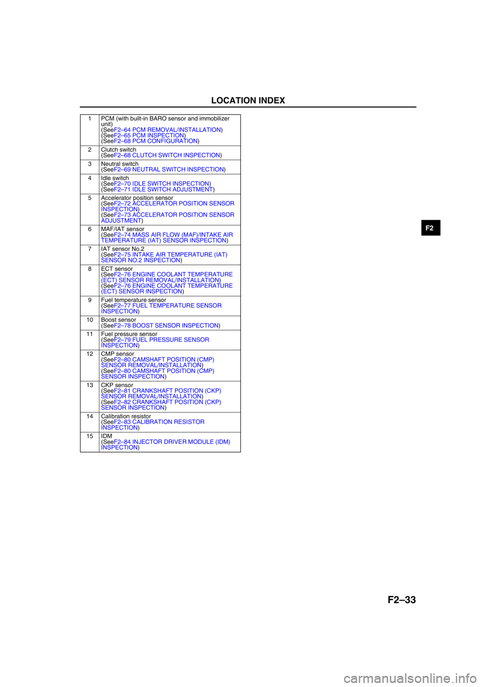
1 PCM (with built-in BARO sensor and immobilizer
unit)
(SeeF2–64 PCM REMOVAL/INSTALLATION)
(SeeF2–65 PCM INSPECTION)
(SeeF2–68 PCM CONFIGURATION)
2 Clutch switch
(SeeF2–68 CLUTCH SWITCH INSPECTION)
3 Neutral switch
(SeeF2–69 NEUTRAL SWITCH INSPECTION)
4 Idle switch
(SeeF2–70 IDLE SWITCH INSPECTION)
(SeeF2–71 IDLE SWITCH ADJUSTMENT)
5 Accelerator position sensor
(SeeF2–72 ACCELERATOR POSITION SENSOR
INSPECTION)
(SeeF2–73 ACCELERATOR POSITION SENSOR
ADJUSTMENT)
6 MAF/IAT sensor
(SeeF2–74 MASS AIR FLOW (MAF)/INTAKE AIR
TEMPERATURE (IAT) SENSOR INSPECTION)
7 IAT sensor No.2
(SeeF2–75 INTAKE AIR TEMPERATURE (IAT)
SENSOR NO.2 INSPECTION)
8ECT sensor
(SeeF2–76 ENGINE COOLANT TEMPERATURE
(ECT) SENSOR REMOVAL/INSTALLATION)
(SeeF2–76 ENGINE COOLANT TEMPERATURE
(ECT) SENSOR INSPECTION)
9 Fuel temperature sensor
(SeeF2–77 FUEL TEMPERATURE SENSOR
INSPECTION)
10 Boost sensor
(SeeF2–78 BOOST SENSOR INSPECTION)
11 Fuel pressure sensor
(SeeF2–79 FUEL PRESSURE SENSOR
INSPECTION)
12 CMP sensor
(SeeF2–80 CAMSHAFT POSITION (CMP)
SENSOR REMOVAL/INSTALLATION)
(SeeF2–80 CAMSHAFT POSITION (CMP)
SENSOR INSPECTION)
13 CKP sensor
(SeeF2–81 CRANKSHAFT POSITION (CKP)
SENSOR REMOVAL/INSTALLATION)
(SeeF2–82 CRANKSHAFT POSITION (CKP)
SENSOR INSPECTION)
14 Calibration resistor
(SeeF2–83 CALIBRATION RESISTOR
INSPECTION)
15 IDM
(SeeF2–84 INJECTOR DRIVER MODULE (IDM)
INSPECTION)
Page 324 of 909

F2–172
TROUBLESHOOTING
×: Applicable
End Of Sie
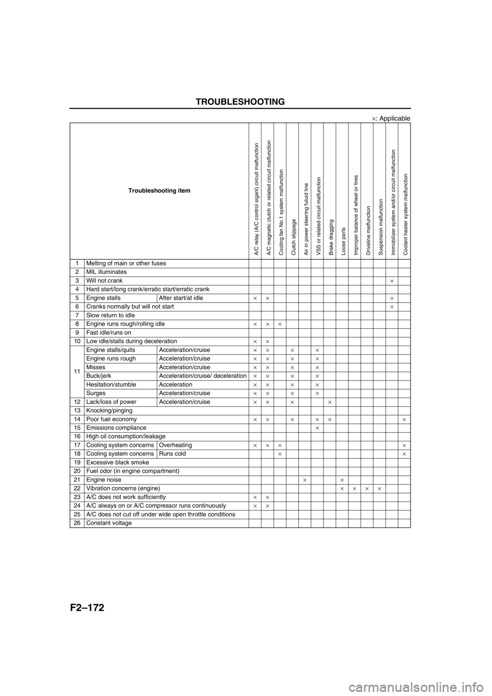
Troubleshooting item
1 Melting of main or other fuses
2 MIL illuminates
3 Will not crank×
4 Hard start/long crank/erratic start/erratic crank
5 Engine stalls After start/at idle×× ×
6 Cranks normally but will not start×
7 Slow return to idle
8 Engine runs rough/rolling idle×××
9 Fast idle/runs on
10 Low idle/stalls during deceleration××
11Engine stalls/quits Acceleration/cruise××××
Engine runs rough Acceleration/cruise××××
Misses Acceleration/cruise××××
Buck/jerk Acceleration/cruise/ deceleration××××
Hesitation/stumble Acceleration××××
Surges Acceleration/cruise××××
12 Lack/loss of power Acceleration/cruise×× × ×
13 Knocking/pinging
14 Poor fuel economy××××× ×
15 Emissions compliance×
16 High oil consumption/leakage
17 Cooling system concerns Overheating××× ×
18 Cooling system concerns Runs cold××
19 Excessive black smoke
20 Fuel odor (in engine compartment)
21 Engine noise××
22 Vibration concerns (engine)××××
23 A/C does not work sufficiently××
24 A/C always on or A/C compressor runs continuously××
25 A/C does not cut off under wide open throttle conditions
26 Constant voltage
A/C relay (A/C control siganl) circuit malfunctionA/C magnetic clutch or related circuit malfunctionCooling fan No.1 system malfunctionClutch slippageAir in power steering fuluid lineVSS or related circuit malfunctionBrake draggingLoose partsImproper balance of wheel or tiresDriveline malfunctionSuspension malfunctionImmobilizer system and/or circuit malfunctionCoolant heater system malfunction
Page 326 of 909

F2–174
TROUBLESHOOTING
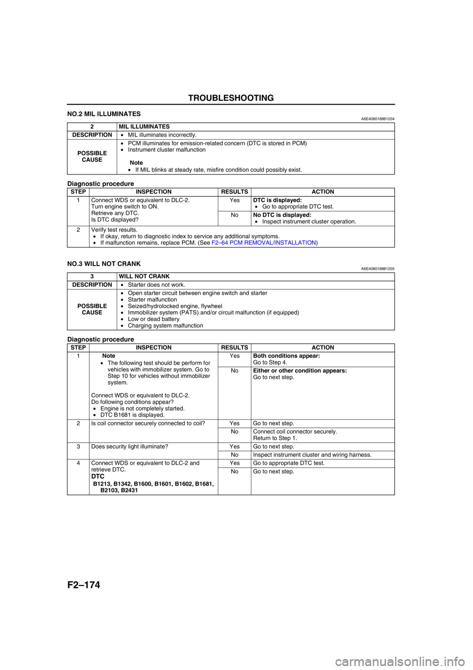
NO.2 MIL ILLUMINATESA6E408018881204
Diagnostic procedure
End Of Sie
NO.3 WILL NOT CRANKA6E408018881205
Diagnostic procedure
2 MIL ILLUMINATES
DESCRIPTION•MIL illuminates incorrectly.
POSSIBLE
CAUSE•PCM illuminates for emission-related concern (DTC is stored in PCM)
•Instrument cluster malfunction
Note
•If MIL blinks at steady rate, misfire condition could possibly exist.
STEP INSPECTION RESULTS ACTION
1 Connect WDS or equivalent to DLC-2.
Turn engine switch to ON.
Retrieve any DTC.
Is DTC displayed?YesDTC is displayed:
•Go to appropriate DTC test.
NoNo DTC is displayed:
•Inspect instrument cluster operation.
2 Verify test results.
•If okay, return to diagnostic index to service any additional symptoms.
•If malfunction remains, replace PCM. (See F2–64 PCM REMOVAL/INSTALLATION)
3 WILL NOT CRANK
DESCRIPTION•Starter does not work.
POSSIBLE
CAUSE•Open starter circuit between engine switch and starter
•Starter malfunction
•Seized/hydrolocked engine, flywheel
•Immobilizer system (PATS) and/or circuit malfunction (if equipped)
•Low or dead battery
•Charging system malfunction
STEP INSPECTION RESULTS ACTION
1Note
•The following test should be perform for
vehicles with immobilizer system. Go to
Step 10 for vehicles without immobilizer
system.
Connect WDS or equivalent to DLC-2.
Do following conditions appear?
•Engine is not completely started.
•DTC B1681 is displayed.YesBoth conditions appear:
Go to Step 4.
NoEither or other condition appears:
Go to next step.
2 Is coil connector securely connected to coil? Yes Go to next step.
No Connect coil connector securely.
Return to Step 1.
3 Does security light illuminate? Yes Go to next step.
No Inspect instrument cluster and wiring harness.
4 Connect WDS or equivalent to DLC-2 and
retrieve DTC.
DTC
B1213, B1342, B1600, B1601, B1602, B1681,
B2103, B2431Yes Go to appropriate DTC test.
No Go to next step.
Page 330 of 909

F2–178
TROUBLESHOOTING
End Of Sie
NO.5 ENGINE STALLS-AFTER START/AT IDLEA6E408018881207
Diagnostic Procedure
18 Verify test results.
•If okay, return to diagnostic index to service any additional symptoms.
•If malfunction remains, replace PCM. (See F2–64 PCM REMOVAL/INSTALLATION) STEP INSPECTION RESULTS ACTION
5 ENGINE STALLS-AFTER START/AT IDLE
DESCRIPTION•Engine stops unexpectedly.
POSSIBLE
CAUSE•Poor fuel quality
•Intake-air system restriction or clogging
•Engine overheating
•A/C system improper operation
•Immobilizer system (PATS) and/or circuit malfunction (if equipped)
•PCM control relay malfunction
•Glow system malfunction
•Inadequate fuel pressure
•Fuel pressure sensor related circuit malfunction
•Suction control valve malfunction (built-in supply pump)
•Fuel pressure limiter malfunction (built-in common rail)
•Fuel leakage
•Fuel line clogging or restriction
•Fuel filter clogging or restriction
•Incorrect fuel injection timing
•Erratic signal from CKP sensor
•Erratic signal from CMP sensor
•Supply pump malfunction
•Fuel injector malfunction
•Low engine compression
•Improper valve timing
•Exhaust system and/or catalyst converter restriction or clogging
•EGR system malfunction
•ECT sensor or related circuit malfunction
•Accelerator positions sensor or related circuit malfunction
•Accelerator positions sensor misadjustment
•MAF/IAT sensor or related circuit malfunction
•V-reference voltage supply circuit malfunction
•IDM or related circuit malfunction
Warning
The following troubleshooting flow chart contains the fuel system diagnosis and repair
procedures. Read the following warnings before performing the fuel system services:
•Fuel vapor is hazardous. It can easily ignite, causing serious injury and damage. Always keep
sparks and flames away from fuel.
•Fuel line spills and leakage are dangerous. Fuel can ignite and cause serious injury or death
and damage. Fuel can also irritate skin and eyes. To prevent this, always complete “BEFORE
REPAIR PROCEDURE” and “AFTER REPAIR PROCEDURE” described in this manual.
STEP INSPECTION RESULTS ACTION
1Note
•The following test should be perform for
vehicles with immobilizer system. Go to
Step 10 for vehicles without immobilizer
system.
Connect WDS or equivalent to DLC-2.
Do following conditions appear?
•Engine is not completely started.
•DTC B1681 is displayed.YesBoth conditions appear:
Go to Step 4.
NoEither or other condition appears:
Go to next step.
2 Is coil connector securely connected to coil? Yes Go to next step.
No Connect coil connector securely.
Return to Step 1.
3 Does security light illuminate? Yes Go to next step.
No Inspect instrument cluster and wiring harness.
Page 333 of 909

TROUBLESHOOTING
F2–181
F2
End Of Sie
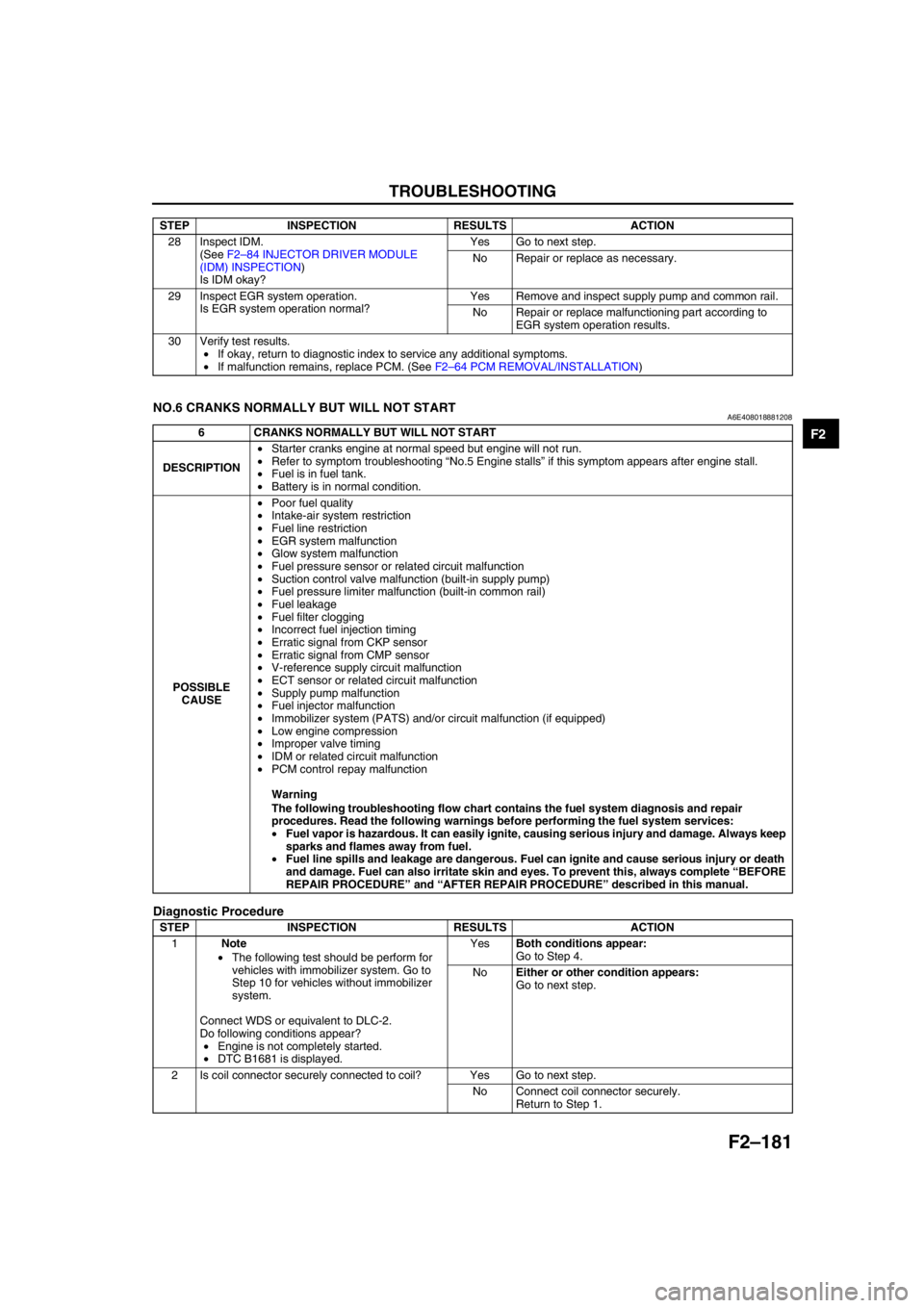
NO.6 CRANKS NORMALLY BUT WILL NOT STARTA6E408018881208
Diagnostic Procedure
28 Inspect IDM.
(See F2–84 INJECTOR DRIVER MODULE
(IDM) INSPECTION)
Is IDM okay?Yes Go to next step.
No Repair or replace as necessary.
29 Inspect EGR system operation.
Is EGR system operation normal?Yes Remove and inspect supply pump and common rail.
No Repair or replace malfunctioning part according to
EGR system operation results.
30 Verify test results.
•If okay, return to diagnostic index to service any additional symptoms.
•If malfunction remains, replace PCM. (See F2–64 PCM REMOVAL/INSTALLATION) STEP INSPECTION RESULTS ACTION
6 CRANKS NORMALLY BUT WILL NOT START
DESCRIPTION•Starter cranks engine at normal speed but engine will not run.
•Refer to symptom troubleshooting “No.5 Engine stalls” if this symptom appears after engine stall.
•Fuel is in fuel tank.
•Battery is in normal condition.
POSSIBLE
CAUSE•Poor fuel quality
•Intake-air system restriction
•Fuel line restriction
•EGR system malfunction
•Glow system malfunction
•Fuel pressure sensor or related circuit malfunction
•Suction control valve malfunction (built-in supply pump)
•Fuel pressure limiter malfunction (built-in common rail)
•Fuel leakage
•Fuel filter clogging
•Incorrect fuel injection timing
•Erratic signal from CKP sensor
•Erratic signal from CMP sensor
•V-reference supply circuit malfunction
•ECT sensor or related circuit malfunction
•Supply pump malfunction
•Fuel injector malfunction
•Immobilizer system (PATS) and/or circuit malfunction (if equipped)
•Low engine compression
•Improper valve timing
•IDM or related circuit malfunction
•PCM control repay malfunction
Warning
The following troubleshooting flow chart contains the fuel system diagnosis and repair
procedures. Read the following warnings before performing the fuel system services:
•Fuel vapor is hazardous. It can easily ignite, causing serious injury and damage. Always keep
sparks and flames away from fuel.
•Fuel line spills and leakage are dangerous. Fuel can ignite and cause serious injury or death
and damage. Fuel can also irritate skin and eyes. To prevent this, always complete “BEFORE
REPAIR PROCEDURE” and “AFTER REPAIR PROCEDURE” described in this manual.
STEP INSPECTION RESULTS ACTION
1Note
•The following test should be perform for
vehicles with immobilizer system. Go to
Step 10 for vehicles without immobilizer
system.
Connect WDS or equivalent to DLC-2.
Do following conditions appear?
•Engine is not completely started.
•DTC B1681 is displayed.YesBoth conditions appear:
Go to Step 4.
NoEither or other condition appears:
Go to next step.
2 Is coil connector securely connected to coil? Yes Go to next step.
No Connect coil connector securely.
Return to Step 1.