water pump MAZDA 6 2002 Workshop Manual Suplement
[x] Cancel search | Manufacturer: MAZDA, Model Year: 2002, Model line: 6, Model: MAZDA 6 2002Pages: 909, PDF Size: 17.16 MB
Page 8 of 909

NEW STANDARDS
GI–5
GINEW STANDARDS TABLEA6E202800020201•The following is a comparison of the previous standard and the new standard.
NEW STANDARDS
New Standard Previous Standard
Remark
Abbrevi-
ationNameAbbrevi-
ationName
AP Accelerator Pedal—Accelerator Pedal
ACL Air Cleaner—Air Cleaner
A/C Air Conditioning—Air Conditioning
BARO Barometric Pressure—Atmospheric Pressure
B+ Battery Positive VoltageV
BBattery Voltage
—Brake Switch—Stoplight Switch
—Calibration Resistor—Corrected Resistance #6
CMP sensor Camshaft Position Sensor—Crank Angle Sensor
CAC Charge Air Cooler—Intercooler
CLS Closed Loop System—Feedback System
CTP Closed Throttle Position—Fully Closed
—Closed Throttle Position Switch—Idle Switch
CPP Clutch Pedal Position—Clutch Position
CIS Continuous Fuel Injection System EGI Electronic Gasoline Injection System
CS sensor Control Sleeve Sensor CSP sensor Control Sleeve Position Sensor #6
CKP sensor Crankshaft Position Sensor—Crank Angle Sensor 2
DLC Data Link Connector—Diagnosis Connector
DTM Diagnostic Test Mode—Test Mode #1
DTC Diagnostic Trouble Code—Service Code(s)
DI Distributor Ignition—Spark Ignition
DLI Distributorless Ignition—Direct Ignition
EI Electronic Ignition—Electronic Spark Ignition #2
ECT Engine Coolant Temperature—Water Thermo
EM Engine Modification—Engine Modification
—Engine Speed Input Signal—Engine RPM Signal
EVAP Evaporative Emission—Evaporative Emission
EGR Exhaust Gas Recirculation—Exhaust Gas Recirculation
FC Fan Control—Fan Control
FF Flexible Fuel—Flexible Fuel
4GR Fourth Gear—Overdrive
—Fuel Pump Relay—Circuit Opening Relay #3
FSO
solenoidFuel Shut Off Solenoid FCV Fuel Cut Valve #6
GEN Generator—Alternator
GND Ground—Ground/Earth
HO2S Heated Oxygen Sensor—Oxygen Sensor With heater
IAC Idle Air Control—Idle Speed Control
—IDM Relay—Spill Valve Relay #6
—Incorrect Gear Ratio——
—Injection Pump FIP Fuel Injection Pump #6
—Input/Turbine Speed Sensor—Pulse Generator
IAT Intake Air Temperature—Intake Air Thermo
KS Knock Sensor—Knock Sensor
MIL Malfunction Indicator Lamp—Malfunction Indicator Light
MAP Manifold Absolute Pressure—Intake Air Pressure
MAF sensor Mass Air Flow Sensor—Airflow Sensor
MFI Multiport Fuel Injection—Multiport Fuel Injection
OBD On Board Diagnostic—Diagnosis/Self Diagnosis
Page 44 of 909
TIMING BELT
B2–13
B2
Caution
•To prevent the bolts (M8 x 1.25) from damaging the fuel injection pump and pulley, do not fully
tighten the fixing bolts. If it contacts the pulley surface, it will damage the pulley.
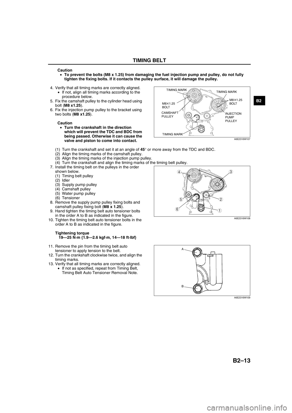
4. Verify that all timing marks are correctly aligned.
•If not, align all timing marks according to the
procedure below.
5. Fix the camshaft pulley to the cylinder head using
bolt (M8 x1.25).
6. Fix the injection pump pulley to the bracket using
two bolts (M8 x1.25).
Caution
•Turn the crankshaft in the direction
which will prevent the TDC and BDC from
being passed. Otherwise it can cause the
valve and piston to come into contact.
(1) Turn the crankshaft and set it at an angle of 45° or more away from the TDC and BDC.
(2) Align the timing marks of the camshaft pulley.
(3) Align the timing marks of the injection pump pulley.
(4) Turn the crankshaft and align the timing marks of the timing belt pulley.
7. Install the timing belt on the pulleys in the order
shown below.
(1) Timing belt pulley
(2) Idler
(3) Supply pump pulley
(4) Camshaft pulley
(5) Water pump pulley
(6) Tensioner
8. Remove the supply pump pulley fixing bolts and
camshaft pulley fixing bolt (M8 x 1.25).
9. Hand tighten the timing belt auto tensioner bolts
in the order A to B as indicated in the figure.
10. Tighten the timing belt auto tensioner bolts in the
order A to B as indicated in the figure.
Tightening torque
19—25 N·m {1.9—2.6 kgf·m, 14—18 ft·lbf}
11. Remove the pin from the timing belt auto
tensioner to apply tension to the belt.
12. Turn the crankshaft clockwise twice, and align the
timing marks.
13. Verify that all timing marks are correctly aligned.
•If not as specified, repeat from Timing Belt,
Timing Belt Auto Tensioner Removal Note.
TIMING MARK
TIMING MARKTIMING MARK
M8 1.25
BOLT
M8 1.25
BOLT
CAMSHAFT
PULLEYINJECTION
PUMP
PULLEY
A6E2316W107
5
43
1
2
6
A6E2316W108
A
B
A6E2316W109
Page 47 of 909
B2–16
CYLINDER HEAD GASKET
.
SST
SST
SSTR
R
R
R
R
SEALANTSEALANT
SEALANTSEALANT
SEALANTSEALANT
SEALANTSEALANT
SEALANTSEALANT
OILOIL
OILOIL
7.9—10.7 N·m
{80—110 kgf·cm,
69.5—95.4 in·lbf}
7.9—10.7 N·m
{80—110 kgf·cm,
69.5—95.4 in·lbf}
7.9—10.7 N·m
{80—110 kgf·cm,
69.5—95.4 in·lbf} 7.9—10.7 N·m
{80—110 kgf·cm,
69.5—95.4 in·lbf}
7.9—10.7 N·m
{80—110 kgf·cm,
69.5—95.4 in·lbf}55—64
{5.6—6.6, 41—47}
38—51
{3.8—5.3,
28—38}
52—61
{5.3—6.3,
39—45}
29 {3.0, 22}
+90 105
+90 105
+90 105
50—60
{5.0—6.0,
37—44}
19—25
{1.9—2.6,
14—18}
50—60 {5.0—6.0, 37—44}
46—58 {4.6—6.0, 34—43} 59—68
{6.0—7.0, 44—50}25—30
{2.5—3.1, 18—22}
38—51
{3.8—5.3,
28—38}19—25
{1.9—2.6,
14—18}
N·m {kgf·m, ft·lbf}
98
7
54
3
1
2
10
19
18
17
15
16
14
13
11
12
20
25
24
2321
22
6
SST
55—64
{5.6—6.6, 41—47}
—
— —
39—44
{4.0—4.4,
28.8—32.4}
22—26
{2.2—2.7,
16—19}
SEALANTSEALANT
A6E2318W100
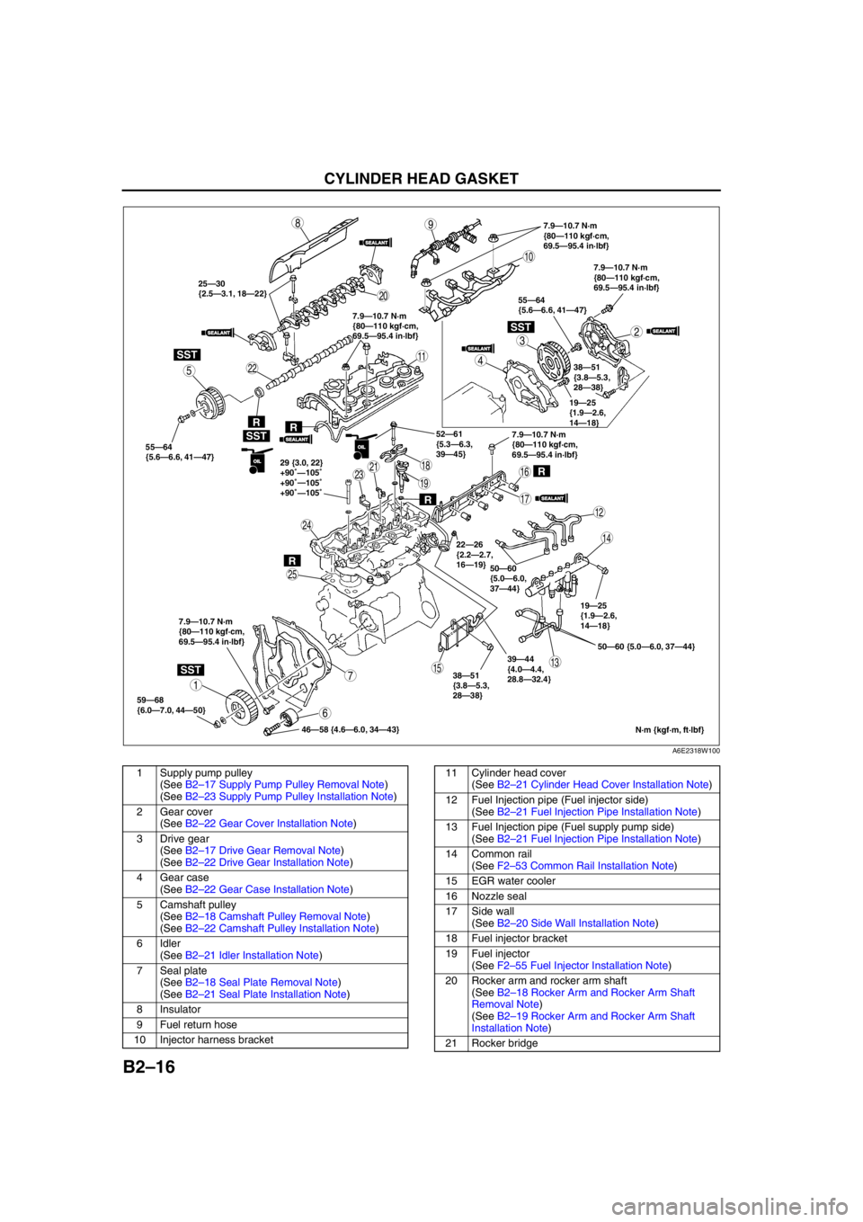
1 Supply pump pulley
(See B2–17 Supply Pump Pulley Removal Note)
(See B2–23 Supply Pump Pulley Installation Note)
2 Gear cover
(See B2–22 Gear Cover Installation Note)
3 Drive gear
(See B2–17 Drive Gear Removal Note)
(See B2–22 Drive Gear Installation Note)
4 Gear case
(See B2–22 Gear Case Installation Note)
5 Camshaft pulley
(See B2–18 Camshaft Pulley Removal Note)
(See B2–22 Camshaft Pulley Installation Note)
6 Idler
(See B2–21 Idler Installation Note)
7 Seal plate
(See B2–18 Seal Plate Removal Note)
(See B2–21 Seal Plate Installation Note)
8 Insulator
9 Fuel return hose
10 Injector harness bracket11 Cylinder head cover
(See B2–21 Cylinder Head Cover Installation Note)
12 Fuel Injection pipe (Fuel injector side)
(See B2–21 Fuel Injection Pipe Installation Note)
13 Fuel Injection pipe (Fuel supply pump side)
(See B2–21 Fuel Injection Pipe Installation Note)
14 Common rail
(See F2–53 Common Rail Installation Note)
15 EGR water cooler
16 Nozzle seal
17 Side wall
(See B2–20 Side Wall Installation Note)
18 Fuel injector bracket
19 Fuel injector
(See F2–55 Fuel Injector Installation Note)
20 Rocker arm and rocker arm shaft
(See B2–18 Rocker Arm and Rocker Arm Shaft
Removal Note)
(See B2–19 Rocker Arm and Rocker Arm Shaft
Installation Note)
21 Rocker bridge
Page 66 of 909

D–2
OUTLINE
OUTLINE OF CONSTRUCTIONA6E330202000201•The construction and the operation of the oil cooler and the oil filter for the new Mazda6 (GG, GY) MZR-CD (RF
Turbo) engine model is the same as the current Mazda MPV (LW) MZR-CD (RF Turbo) engine model. (See
Mazda MPV Workshop Manual Supplement 1737-1*-02D.)
•The construction and the operation of the lubrication system except for the oil cooler and oil filter for the new
Mazda6 (GG, GY) MZR-CD (RF Turbo) engine model is the same as the current Mazda 626, 626 Station
Wagon (GF, GW) RF Turbo engine model. (European specs.) (See Mazda 626, 626 Station Wagon RF Turbo
Workshop Manual Supplement 1614-10-98D.)
•The construction and the operation of the lubrication system for the new Mazda6 (GG, GY) L8, LF, and L3
engine models is the same as the current Mazda6 (GG) engine model L8, LF, and L3 engine models. (See
Mazda6 Training Manual 3359-1*-02C, Mazda6 Workshop Manual 1730-1*-02C.)
End Of Sie
SPECIFICATIONSA6E330202000202Gasoline engine
* : Always verify the oil level with the dipsticks since the engine oil capacity differs according to dipstick
specifications. (See Mazda6 Workshop Manual 1730-1*-02C Section D.)
Recommended Engine Oil (Gasoline Engine)
•The maintenance intervals on the scheduled maintenance table (See GI–8 SCHEDULED MAINTENANCE
TABLE) can only be supported with the use of following oils.
OUTLINE
ItemSpecification
New
Mazda6
(GG, GY)Current
Mazda6
(GG)New
Mazda6
(GG, GY)Current
Mazda6
(GG)New
Mazda6
(GG, GY)Current
Mazda6
(GG)
L8 LF L3*
Lubrication system Force-fed type
Oil coolerWater-cooled
Oil pressure
(approximate quantity)
[oil temperature: 100°C
{212°F}](kPa {kgf/cm
2, psi})
min [rpm]234—521
{2.39—5.31, 33.9—75.5}
[3,000]395—649
{4.03—6.61,
57.3—94.1}
[3,000]
Oil pumpType Trochoid gear type
Relief pressure
(approximate
quantity) (kPa {kgf/cm
2,
psi})500—600
{5.09—6.11, 72.6—87.0}
Oil filterType Full-flow, Paper element
Bypass pressure
(approximate
quantity)(kPa kgf/cm
2, psi})80—120
{0.9—1.2, 12.8—17.0}
Oil capacity
(approximate
quantity)Total
(dry engine)(L {US qt, lmp qt}) 4.6 {4.8, 4.0} Dipstick A: 4.2 {4.4, 3.7}
Dipstick B: 5.1 {5.4, 4.5}
Oil replacement (L {US qt, lmp qt}) 3.9 {4.0, 3.4} Dipstick A: 3.1 {3.3, 2.7}
Dipstick B: 4.0 {4.2, 3.5}
Oil and oil filter
replacement(L {US qt, lmp qt}) 4.3 {4.5, 3.8} Dipstick A: 3.5 {3.7, 3.1}
Dipstick B: 4.4 {4.6, 3.9}
ItemSpecification
New Mazda6
(GG, GY), Current Mazda6
(GG)New Mazda6
(GG, GY), Current Mazda6
(GG)
L8, LF, L3
Engine oil GradeAPI SL
ACEA A3
Viscosity (SAE) 5W-30, 10W-40 5W-20
RemarksMazda genuine Dexelia oil e.g. —
Page 67 of 909

OUTLINE
D–3
D
Diesel engine
Bold frames: New specifications
Recommended Engine Oil (Diesel Engine)
•The maintenance intervals on the scheduled maintenance table (See GI–8 SCHEDULED MAINTENANCE
TABLE) can only be supported with the use of following oils.
Bold frames: New specifications
End Of Sie
ItemSpecification
New Mazda6
(GG, GY)Current
Mazda 626, 626
Station Wagon
(GF, GW)Current
Mazda MPV
(LW)
MZR-CD (RF Turbo) RF TurboMZR-CD (RF
Turbo)
Lubrication system Force-fed type—
Oil cooler Water-cooled—
Oil pressure
(approximate quantity)
[oil temperature: 100°C {212°F}](kPa {kgf/cm
2, psi})
min [rpm]147 {1.5, 21} [1,000],
343 {3.5, 50} [3,000]—
Oil pumpType Trochoid gear type—Trochoid gear type
Relief pressure
(approximate
quantity)(kPa {kgf/cm
2, psi})
[rpm]580—700
{5.9—7.1,
84.1—101.5}
[3,000]—580—700
{5.9—7.1,
84.1—101.5}
[3,000]
Oil filterTypeFull-flow,
Paper element—Full-flow,
Paper element
Bypass pressure
(approximate
quantity)(kPa kgf/cm
2, psi})78—118
{0.8—1.2,
11.3—17.1} —78—118
{0.8—1.2,
11.3—17.1}
Oil capacity
(approximate
quantity)Total
(dry engine)(L {US qt, lmp qt}) 5.5 {5.8, 4.8} 5.4 {5.7, 4.8} —
Oil replacement (L {US qt, lmp qt}) 4.8 {5.1, 4.2} 4.5 {4.8, 4.0}—
Oil and oil filter
replacement(L {US qt, lmp qt}) 5.0 {5.3 ,4.4} 4.7 {5.0, 4.1} —
ItemSpecification
New Mazda6
(GG, GY)Current
Mazda 626, 626
Station Wagon
(GF, GW)
MZR-CD (RF Turbo) RF Turbo
Engine oil GradeAPI CF CD, CE, CF-4 CD
ACEA B1 or B3 B3 B3 or B4—
Viscosity (SAE) 5W-30 10W-40 5W-30, 10W-30 5W-30, 10W-30
RemarksMazda genuine
Dexelia oil e.g.——
Page 76 of 909
E–1
E
ECOOLING SYSTEM
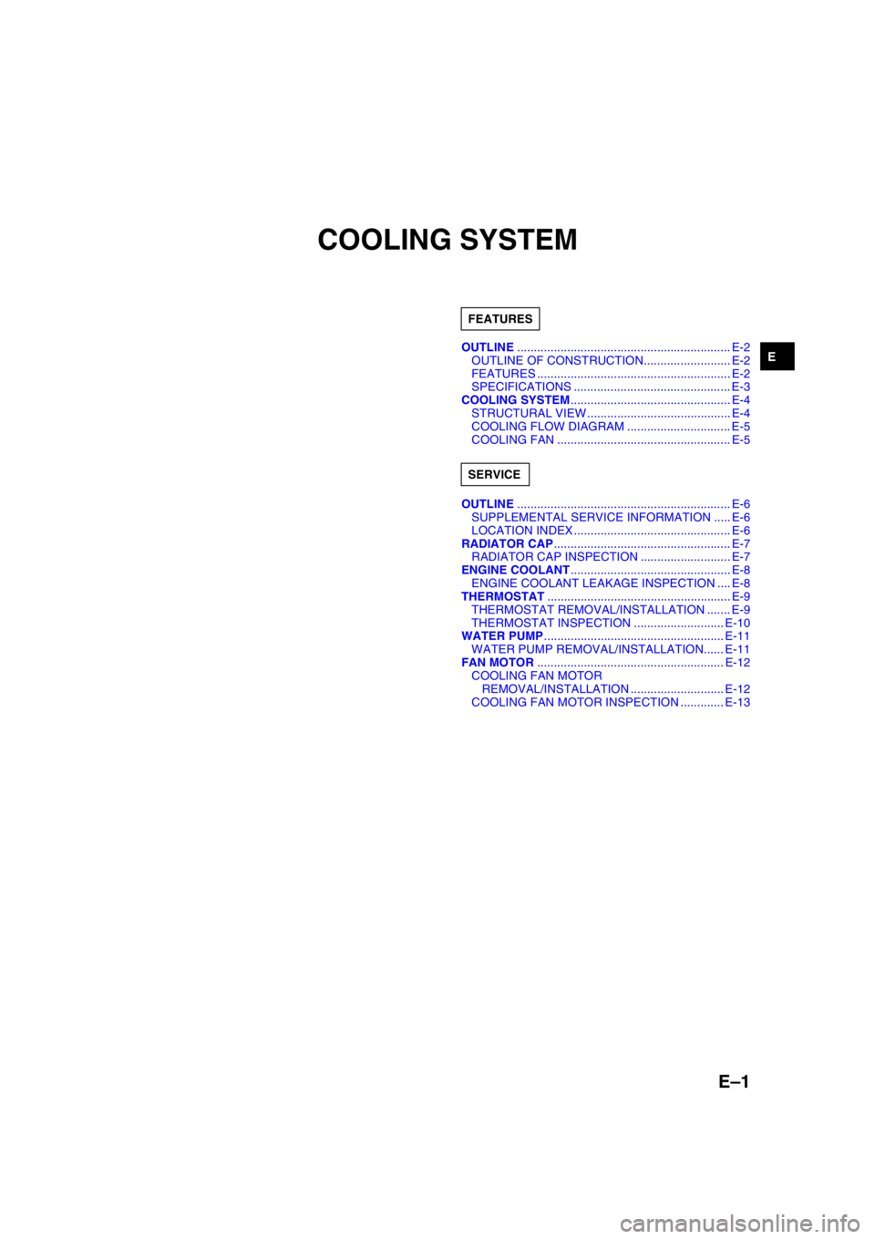
OUTLINE................................................................ E-2
OUTLINE OF CONSTRUCTION.......................... E-2
FEATURES .......................................................... E-2
SPECIFICATIONS ............................................... E-3
COOLING SYSTEM................................................ E-4
STRUCTURAL VIEW ........................................... E-4
COOLING FLOW DIAGRAM ............................... E-5
COOLING FAN .................................................... E-5
OUTLINE................................................................ E-6
SUPPLEMENTAL SERVICE INFORMATION ..... E-6
LOCATION INDEX ............................................... E-6
RADIATOR CAP..................................................... E-7
RADIATOR CAP INSPECTION ........................... E-7
ENGINE COOLANT................................................ E-8
ENGINE COOLANT LEAKAGE INSPECTION .... E-8
THERMOSTAT....................................................... E-9
THERMOSTAT REMOVAL/INSTALLATION ....... E-9
THERMOSTAT INSPECTION ........................... E-10
WATER PUMP...................................................... E-11
WATER PUMP REMOVAL/INSTALLATION...... E-11
FAN MOTOR........................................................ E-12
COOLING FAN MOTOR
REMOVAL/INSTALLATION ............................ E-12
COOLING FAN MOTOR INSPECTION ............. E-13 FEATURES
SERVICE
Page 77 of 909

E–2
OUTLINE
OUTLINE OF CONSTRUCTIONA6E360202000205•The construction and operation of the water pump and the thermostat for the new Mazda6 (GG, GY) MZR-CD
(RF Turbo) engine model are the same as the current Mazda 323 (BJ) RF Turbo engine model. (European
specs.) (See Mazda 323 RF Turbo Workshop Manual Supplement 1633-10-98G.)
•The construction and operation of the cooling system except for the water pump and the thermostat for the new
Mazda6 (GG, GY) MZR-CD (RF Turbo) engine model are the same as the current Mazda6 (GG) L3 engine
model except for the following features. (See Mazda6 Training Manual 3359-1*-02C.)
•The construction and operation of the engine cooling system for the new Mazda6 (GG, GY) L8, LF, and L3
engine models is the same as the current Mazda6 (GG) L8, LF, and L3 engine models. (See Mazda6 Training
Manual 3359-1*-02C.)
End Of Sie
FEATURESA6E360202000206Modification to fit the engine performance
•Cooling fan motor output has been changed. (MZR-CD (RF Turbo) engine model)
End Of Sie
OUTLINE
Page 78 of 909
OUTLINE
E–3
E
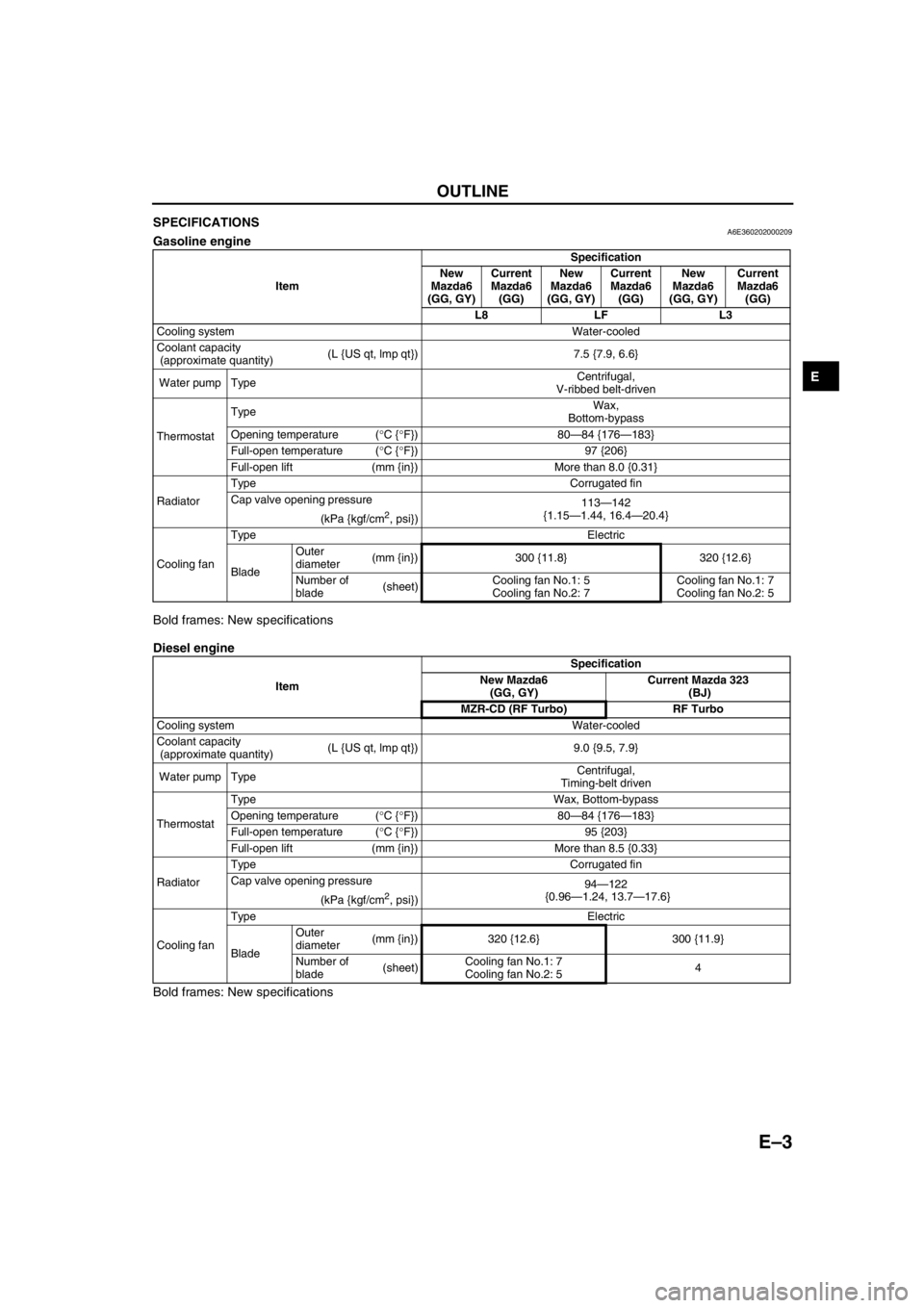
SPECIFICATIONSA6E360202000209Gasoline engine
Bold frames: New specifications
Diesel engine
Bold frames: New specifications
End Of Sie
ItemSpecification
New
Mazda6
(GG, GY)Current
Mazda6
(GG)New
Mazda6
(GG, GY)Current
Mazda6
(GG)New
Mazda6
(GG, GY)Current
Mazda6
(GG)
L8 LF L3
Cooling system Water-cooled
Coolant capacity
(approximate quantity)(L {US qt, lmp qt}) 7.5 {7.9, 6.6}
Water pump TypeCentrifugal,
V-ribbed belt-driven
ThermostatTypeWax,
Bottom-bypass
Opening temperature (°C {°F}) 80—84 {176—183}
Full-open temperature (°C {°F}) 97 {206}
Full-open lift (mm {in}) More than 8.0 {0.31}
RadiatorType Corrugated fin
Cap valve opening pressure
113—142
{1.15—1.44, 16.4—20.4}
(kPa {kgf/cm
2, psi})
Cooling fanType Electric
BladeOuter
diameter(mm {in}) 300 {11.8} 320 {12.6}
Number of
blade(sheet)Cooling fan No.1: 5
Cooling fan No.2: 7Cooling fan No.1: 7
Cooling fan No.2: 5
ItemSpecification
New Mazda6
(GG, GY)Current Mazda 323
(BJ)
MZR-CD (RF Turbo) RF Turbo
Cooling system Water-cooled
Coolant capacity
(approximate quantity)(L {US qt, lmp qt}) 9.0 {9.5, 7.9}
Water pump TypeCentrifugal,
Timing-belt driven
ThermostatType Wax, Bottom-bypass
Opening temperature (°C {°F}) 80—84 {176—183}
Full-open temperature (°C {°F}) 95 {203}
Full-open lift (mm {in}) More than 8.5 {0.33}
RadiatorType Corrugated fin
Cap valve opening pressure
94—122
{0.96—1.24, 13.7—17.6}
(kPa {kgf/cm
2, psi})
Cooling fanType Electric
BladeOuter
diameter(mm {in}) 320 {12.6} 300 {11.9}
Number of
blade(sheet)Cooling fan No.1: 7
Cooling fan No.2: 54
Page 79 of 909
E–4
COOLING SYSTEM
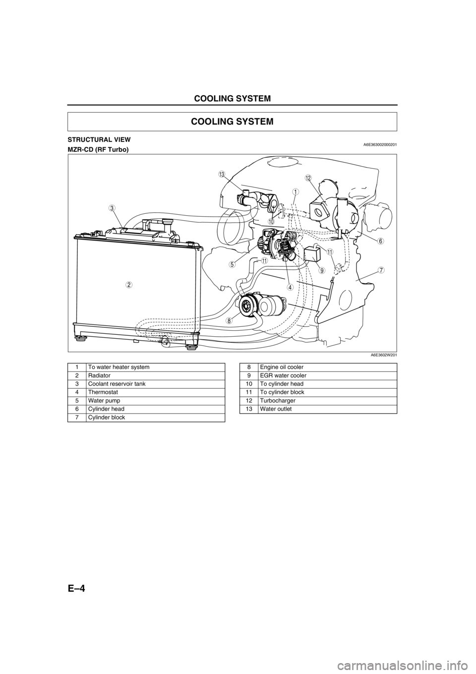
STRUCTURAL VIEWA6E363002000201MZR-CD (RF Turbo)
.
End Of Sie
COOLING SYSTEM
8
75
4
3
1
2
6
10
11
11
9
1312
A6E3602W201
1 To water heater system
2 Radiator
3 Coolant reservoir tank
4Thermostat
5 Water pump
6 Cylinder head
7 Cylinder block8 Engine oil cooler
9EGR water cooler
10 To cylinder head
11 To cylinder block
12 Turbocharger
13 Water outlet
Page 80 of 909
COOLING SYSTEM
E–5
E
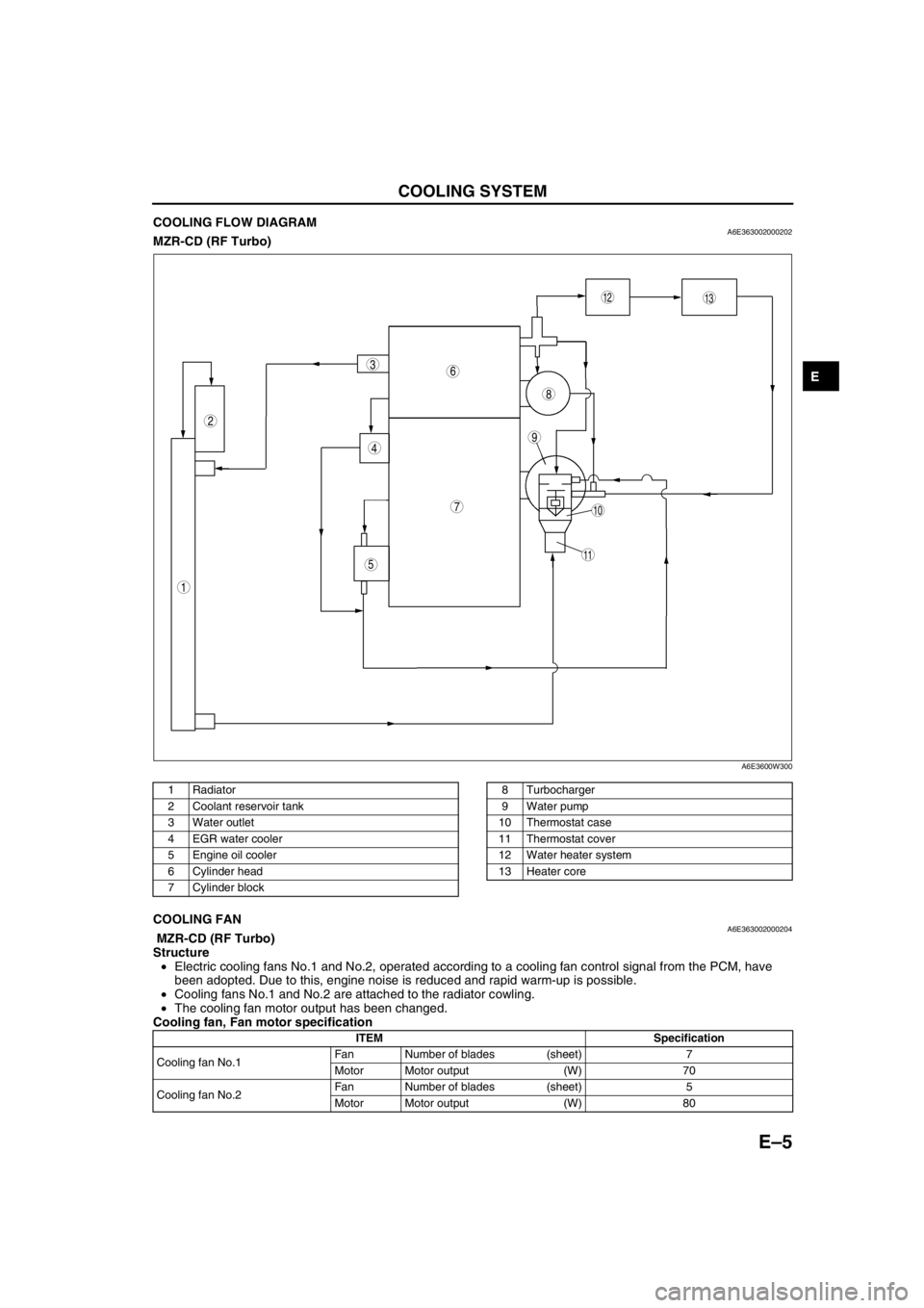
COOLING FLOW DIAGRAMA6E363002000202MZR-CD (RF Turbo)
.
End Of SieCOOLING FANA6E363002000204 MZR-CD (RF Turbo)
Structure
•Electric cooling fans No.1 and No.2, operated according to a cooling fan control signal from the PCM, have
been adopted. Due to this, engine noise is reduced and rapid warm-up is possible.
•Cooling fans No.1 and No.2 are attached to the radiator cowling.
•The cooling fan motor output has been changed.
Cooling fan, Fan motor specification
End Of Sie
9
8
7
5
4
3
1
2
10
13
11
12
6
A6E3600W300
1Radiator
2 Coolant reservoir tank
3 Water outlet
4EGR water cooler
5 Engine oil cooler
6 Cylinder head
7 Cylinder block8 Turbocharger
9 Water pump
10 Thermostat case
11 Thermostat cover
12 Water heater system
13 Heater core
ITEM Specification
Cooling fan No.1Fan Number of blades (sheet) 7
Motor Motor output (W) 70
Cooling fan No.2Fan Number of blades (sheet) 5
Motor Motor output (W) 80