fuel MAZDA 6 2002 Workshop Manual Suplement
[x] Cancel search | Manufacturer: MAZDA, Model Year: 2002, Model line: 6, Model: MAZDA 6 2002Pages: 909, PDF Size: 17.16 MB
Page 816 of 909

MULTIPLEX COMMUNICATION SYSTEM
T–5
T
End Of Sie
Cruise main indicator light
conditions (MZR-CD (RF
Turbo))OUT–––IN
Cruise set indicator light
conditions (MZR-CD (RF
Turbo))OUT–––IN
Desired gear/
selector lever
positionFN4A-EL OUT–IN–IN
JA5AX-EL IN OUT IN IN IN
ECT OUT IN–IN
Engine control condition OUT–IN––
Engine displacement OUT–IN––
Engine loss torque (except
MZR-CD (RF Turbo))OUT IN–––
Engine speed OUT IN IN IN IN
Engine torque (except
MZR-CD (RF Turbo))OUT IN–––
Fuel injection information OUT–IN––
Fuel type and delivery OUT–IN––
Gear position IN OUT IN IN IN
Generator warning light
conditions (except MZR-
CD (RF Turbo))OUT–––IN
Glow indicator light
condition (MZR-CD (RF
Turbo))OUT–––IN
HOLD indicator light
conditions (FN4A-EL)OUT–––IN
Idle speed up request IN OUT–––
MIL condition (except
MZR-CD (RF Turbo))OUT–––IN
MIL indicate request IN OUT–––
Number of cylinders OUT–IN––
Racing select
determinationIN OUT–––
TCC condition IN OUT–––
Tire circumference (front/
rear)OUT–IN––
Torque reduction inhibit OUT IN IN––
TP OUTINININ–
Transmission/axle type OUT–IN––
Travelled distanceIN–OUT––
IN OUT––IN
OUT–––IN
Torque
reduction
requestJA5AX-EL IN OUT–––
except
JA5AX-ELIN–OUT––
Turbine speed IN OUT–––
Upper torque limit IN OUT–––
Vehicle speedOUT–––IN
IN OUT–––
Wheel speed (front left/
front right/rear left/rear
right)IN IN OUT IN–
OUT–––IN
4WD system operating
condition (warning light
information)–––OUT IN SignalMultiplex module
PCM TCMABS (ABS/TCS)
HU/CM or
DSC HU/CM4WD control
moduleInstrument
cluster
Page 821 of 909

T–10
WARNING AND INDICATOR SYSTEM
OUTLINEA6E811801069201•In accordance with the 4WD setting, the following indicator light has been added:
—4WD indicator light
•In accordance with the MZR-CD (RF Turbo) setting, the following indicator lights have been added:
—Glow indicator light
—Sedimentor warning light
•A fuel gauge sender sub-unit has been adopted. (4WD)
End Of Sie
STRUCTURAL VIEWA6E811801069202
.
End Of Sie
WARNING AND INDICATOR SYSTEM
3
2
1
4
5
4WD
A6E81181101
1 Sedimentor warning light
2 4WD indicator light
3 Glow indicator light4 Fuel gauge sender unit
5 Fuel gauge sender sub-unit
Page 822 of 909

WARNING AND INDEICATOR SYSTEM, THEFT-DETERRENT SYSTEM
T–11
T
SYSTEM WIRING DIAGRAMA6E811801069203
.
End Of Sie
OUTLINEA6E812050000201•An intruder sensor has been adopted on the rear part of the roof. (WGN)
•The construction and operation of the theft-deterrent system is the same as that of the current Mazda6 (GG)
model.
End Of Sie
INTRUDER SENSORA6E812050000202Outline
•WGN models are equipped with intruder sensors in two places in the vehicle, due to the necessity of movement
detection in the all around wider vehicle interior. The intruder sensors are located in the roof at the front (with
sliding sunroof), or the center (without sliding sunroof), and the cargo space.
•The structure and operation of the rear intruder sensor is the same as that of the current front and center
intruder sensors.
IG1
B+
1
345
2
6
97
8
2H 2V
1C 2F 2D 2M 2X 2W
A6E81181004
1 Instrument cluster
2Microcomputer
3 Glow indicator light
4 Sedimentor warning light
5 4WD indicator light6 PCM, ABS (ABS/TCS) HU/CM or DSC HU/CM
7 Fuel gauge sender sub-unit (4WD)
8 Fuel gauge sender unit
9 Sedimentor switch
THEFT-DETERRENT SYSTEM
Page 825 of 909

T–14
OUTLINE
SUPPLEMENTAL SERVICE INFORMATIONA6E810201088203•The following changes and/or additions have been made since publication of the Mazda6 Workshop Manual
(1730-1*-02C).
Relay
•Location has been changed.
•Inspection procedure has been modified.
Rear auto leveling sensor
•Removal/Installation procedure has been modified.
High-mount brake light
•Removal/Installation procedure has been modified.
Cargo compartment light
•Removal/Installation procedure has been modified.
•Inspection procedure has been modified.
Rear wiper motor
•Removal/Installation procedure has been modified.
•Inspection procedure has been modified.
Rear wiper arm and blade
•Removal/Installation procedure has been modified.
•Adjustment procedure has been modified.
Rear washer nozzle
•Removal/Installation procedure has been modified.
•Adjustment procedure has been modified.
Rear washer hose
•Removal/Installation procedure has been modified.
Intermittent rear wiper relay
•Removal/Installation procedure has been modified.
Fuel gauge sender unit
•Removal/Installation procedure has been modified.
•Inspection procedure has been modified.
Intruder sensor
•Removal/Installation procedure has been modified.
Noise filter
•Removal/Installation procedure has been modified.
Condenser
•Removal/Installation procedure has been modified.
Antenna feeder
•Location has been changed.
Rear antenna feeder
•Inspection procedure has been modified.
Curtain air bag module
•Removal/Installation procedure has been added.
Air bag module and pre-tensioner seat belt
•Deployment procedure has been modified.
On-board diagnostic
•Multiplex communication system procedure has been modified.
End Of Sie
OUTLINE
Page 828 of 909

LOCATION INDEX
T–17
T
End Of SieWARNING AND INDICATOR SYSTEMA6E810001067201
.
End Of SieTHEFT-DETERRENT SYSTEMA6E810050000201
.
End Of Sie
2
1
A6E81181112
1 Fuel gauge sender sub-unit
(See T–27 FUEL GAUGE SENDER UNIT
REMOVAL/INSTALLATION)
(See T–28 FUEL GAUGE SENDER UNIT
INSPECTION)2 Fuel gauge sender unit
(See T–27 FUEL GAUGE SENDER UNIT
REMOVAL/INSTALLATION)
(See T–28 FUEL GAUGE SENDER UNIT
INSPECTION)
3
12
A6E81201102
1 Front intruder sensor (with sliding sunroof)
2 Center intruder sensor (without sliding sunroof)3 Rear intruder sensor (WGN)
Page 838 of 909

WARNING AND INDICATOR SYSTEM
T–27
T
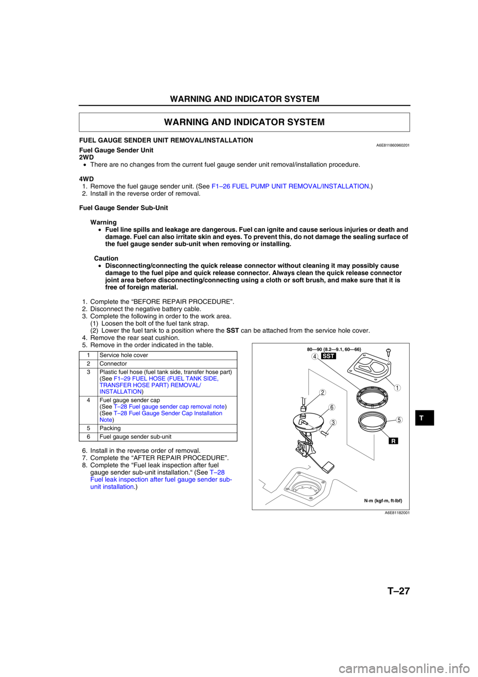
FUEL GAUGE SENDER UNIT REMOVAL/INSTALLATIONA6E811860960201Fuel Gauge Sender Unit
2WD
•There are no changes from the current fuel gauge sender unit removal/installation procedure.
4WD
1. Remove the fuel gauge sender unit. (See F1–26 FUEL PUMP UNIT REMOVAL/INSTALLATION.)
2. Install in the reverse order of removal.
Fuel Gauge Sender Sub-Unit
Warning
•Fuel line spills and leakage are dangerous. Fuel can ignite and cause serious injuries or death and
damage. Fuel can also irritate skin and eyes. To prevent this, do not damage the sealing surface of
the fuel gauge sender sub-unit when removing or installing.
Caution
•Disconnecting/connecting the quick release connector without cleaning it may possibly cause
damage to the fuel pipe and quick release connector. Always clean the quick release connector
joint area before disconnecting/connecting using a cloth or soft brush, and make sure that it is
free of foreign material.
1. Complete the “BEFORE REPAIR PROCEDURE”.
2. Disconnect the negative battery cable.
3. Complete the following in order to the work area.
(1) Loosen the bolt of the fuel tank strap.
(2) Lower the fuel tank to a position where the SST can be attached from the service hole cover.
4. Remove the rear seat cushion.
5. Remove in the order indicated in the table.
6. Install in the reverse order of removal.
7. Complete the “AFTER REPAIR PROCEDURE”.
8. Complete the “Fuel leak inspection after fuel
gauge sender sub-unit installation.“ (See T–28
Fuel leak inspection after fuel gauge sender sub-
unit installation.)
WARNING AND INDICATOR SYSTEM
1 Service hole cover
2 Connector
3 Plastic fuel hose (fuel tank side, transfer hose part)
(See F1–29 FUEL HOSE (FUEL TANK SIDE,
TRANSFER HOSE PART) REMOVAL/
INSTALLATION)
4 Fuel gauge sender cap
(See T–28 Fuel gauge sender cap removal note)
(See T–28 Fuel Gauge Sender Cap Installation
Note)
5 Packing
6 Fuel gauge sender sub-unit
3
1
4
5
6
2
80—90 {8.2—9.1, 60—66}
N·m {kgf·m, ft·lbf}
R
SST
A6E81182001
Page 839 of 909

T–28
WARNING AND INDICATOR SYSTEM
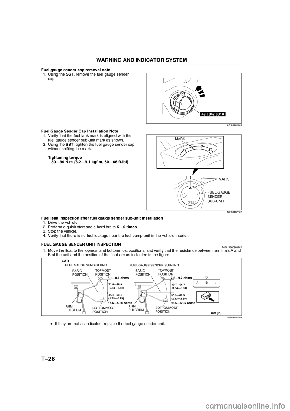
Fuel gauge sender cap removal note
1. Using the SST, remove the fuel gauge sender
cap.
Fuel Gauge Sender Cap Installation Note
1. Verify that the fuel tank mark is aligned with the
fuel gauge sender sub-unit mark as shown.
2. Using the SST, tighten the fuel gauge sender cap
without shifting the mark.
Tightening torque
80—90 N·m {8.2—9.1 kgf·m, 60—66 ft·lbf}
Fuel leak inspection after fuel gauge sender sub-unit installation
1. Drive the vehicle.
2. Perform a quick start and a hard brake 5—6 times.
3. Stop the vehicle.
4. Verify that there is no fuel leakage near the fuel pump unit in the vehicle interior.
End Of Sie
FUEL GAUGE SENDER UNIT INSPECTIONA6E8118609602021. Move the float to the topmost and bottommost positions, and verify that the resistance between terminals A and
B of the unit and the position of the float are as indicated in the figure.
•If they are not as indicated, replace the fuel gauge sender unit.
End Of Sie
49 T042 001A
A6J81182105
FUEL GAUGE
SENDER
SUB-UNIT MARK
MARK
A6E81182002
4WD
44.4—58.4
{1.75—2.29}
TOPMOST
POSITION
BOTTOMMOST
POSITION BASIC
POSITION
ARM
FULCRUM
72.9—86.9
{2.88—3.42}AB
*
53.9—60.9
{2.13—2.39}
TOPMOST
POSITION
BOTTOMMOST
POSITION BASIC
POSITION
ARM
FULCRUM
89.7—96.7
{3.54—3.80}
mm {in}
FUEL GAUGE SENDER UNIT
FUEL GAUGE SENDER SUB-UNIT
6.1—8.1 ohms
57.6—59.6 ohms7.2—9.2 ohms
66.5—68.5 ohms
A6E81181103
Page 864 of 909

U–1
U
UHEATER AND AIR CONDITIONER SYSTEMS
OUTLINE................................................................ U-2
OUTLINE OF CONSTRUCTION.......................... U-2
FEATURES .......................................................... U-2
SPECIFICATIONS ............................................... U-2
CONTROL SYSTEM............................................... U-6
WATER HEATER SYSTEM................................. U-6
OUTLINE................................................................ U-7
SUPPLEMENTAL SERVICE INFORMATION .....U-7
LOCATION INDEX.................................................U-8
BASIC SYSTEM................................................... U-8
CONTROL SYSTEM ............................................ U-9
BASIC SYSTEM................................................... U-10
A/C UNIT REMOVAL/INSTALLATION...............U-10
A/C COMPRESSOR
REMOVAL/INSTALLATION ............................U-11
CONDENSER REMOVAL/INSTALLATION ....... U-12
REFRIGERANT LINES
REMOVAL/INSTALLATION ............................U-13
CONTROL SYSTEM............................................. U-15
WATER HEATER UNIT
REMOVAL/INSTALLATION ............................U-15
FUEL PUMP (WATER HEATER SYSTEM)
INSPECTION .................................................. U-16
CLIMATE CONTROL UNIT INSPECTION.........U-16
ON-BOARD DIAGNOSTIC...................................U-22
FOREWORD ......................................................U-22
DTC TABLE ................................................... U-22-2
PID/DATA MONITOR AND RECORD ........... U-22-2
DTC B1317 .................................................... U-22-3
DTC B1318 ........................................................ U-23
DTC B1342, B2463, B2537, B2538, B2547 ....... U-23
DTC B2449, B2450 ............................................ U-24
DTC B2451, B2452 ............................................ U-24
DTC B2453, B2454 ............................................ U-25
DTC B2548 ........................................................ U-25
TROUBLESHOOTING.......................................... U-26
FOREWORD ......................................................U-26
TROUBLESHOOTING INDEX ...........................U-26 FEATURES
SERVICE
Page 869 of 909

U–6
CONTROL SYSTEM
WATER HEATER SYSTEMA6E854000169201Outline
•The function, structure and operation of the water heater system is essentially carried over from that of the
current MPV (LW) model, except for following:
—Full/half switching temperature has been changed.
Structural View
.
Operation
Full/half switching
•Depending on the engine coolant temperature, the CPU sets the flame to either full or half strength settings.
.
End Of Sie
CONTROL SYSTEM
1
2
A6E85402002
1 Water heater unit2 Fuel pump (water heater system)
3
1
2
68
{154}74
{165}75
{167}78
{172}˚C
{˚F}
A6E85402003
1 Full mode
2 Half mode3 Idle mode
Page 870 of 909

OUTLINE
U–7
U
SUPPLEMENTAL SERVICE INFORMATIONA6E850201038204•The following additions have been made for the MZR-CD (RF Turbo) since the publication of the Mazda6
Workshop Manual (1730-1*-02C).
A/C unit
•Removal/installation procedure has been modified.
A/C compressor
•Removal/installation procedure has been modified.
Condenser
•Removal/installation procedure has been modified.
Refrigerant lines
•Removal/installation procedure has been modified.
Water heater unit
•Removal/installation procedure has been added.
Fuel pump (water heater system)
•Inspection procedure has been added.
Climate control unit
•Inspection procedure has been modified.
Water heater system
•On-board diagnostic system has been added.
End Of Sie
OUTLINE