fuel MAZDA 6 2002 Workshop Manual Suplement
[x] Cancel search | Manufacturer: MAZDA, Model Year: 2002, Model line: 6, Model: MAZDA 6 2002Pages: 909, PDF Size: 17.16 MB
Page 419 of 909

K2–4
AUTOMATIC TRANSAXLE
Bold frames:New specifications
End Of Sie
OUTLINEA6E571401030201•Adopted new JA5AX-EL automatic transaxle.
•Newly designed FF type five-speed automatic transaxle.
—Use of 3 sets of planetary gears, and a wider gear ratio setting realizes improvement of acceleration-from-
standing-start performance, fuel economy, and quietness. Also, by placement of two sets of planetary gears
in parallel with one set, the automatic transaxle is more compact.
•Adopted 2-4 brake clutch.
—Adopted a wet-type, multi-plate 2-4 brake clutch instead of the 2-4 brake band used in the past, for
smoother gear switching performance.
•Adopted centrifugal balance clutch
—The newly adopted centrifugal balance clutch pushes the clutch piston forcefully to low and high clutch by
centrifugal hydraulic pressure for smoother gear switching with batter response.
•Adopted controller area network (CAN)
—By adopting CAN, The TCM is always in contact with other computers in the car and controls the automatic
transaxle properly. This has also made troubleshooting diagnosis easier for the entire vehicle.
•Solenoid, sensor
—Adoption of four duty-type solenoids, five ON-OFF type solenoids, and three revolving sensors realizes
finer, more expedient control of gear shifting performance.
•Adoption of revers inhibit control
—If the reverse position is selected by mistake while driving in forward motion, the reverse inhibit control
system will cancel the operation electronically and set the position to neutral as a safety enhancement.
Outline of Operation
•The operation of the electronic automatic transaxle is classified into three systems: the electronic control
system, the hydraulic pressure control system, and the powertrain system (includes the torque converter
system.)
Electronic control system
•According to the signals from the switches and sensors in the input system, the TCM outputs the signal
which matches the present driving condition to the ON/OFF type solenoids and the duty-cycle type
solenoids in the hydraulic pressure control system.
Hydraulic pressure control system
•According to the signals from the TCM, each solenoid operates to switch the hydraulic passages in the
control valve body and controls the clutch engagement pressure.
•The line pressure is adjusted by the duty-cycle type pressure control solenoid. The hydraulic passages
are switched by the ON/OFF type solenoids and the clutch engagement pressure is controlled by the
duty-cycle type solenoids.
Powertrain system
•The driving force from the engine is transmitted through the torque converter to the transaxle.
•The transmitted driving force operates each clutch and brake according to the clutch engagement
pressure from the duty-cycle type solenoid, and the planetary gears change the gear ratio to the
optimal driving force. The changed driving force is transmitted through the differential to the axle shaft
and then the tires.
AUTOMATIC TRANSAXLE
Page 427 of 909

K2–12
AUTOMATIC TRANSAXLE
Electronic Control Item and Control
Component Description (Electronic Control)
Control item Contents
Shift control•Detects engine load condition and vehicle speed. Shifts to the best gear
position according to the programmed automatic shift diagram.
Line pressure control•Generates line pressure matching the engine load condition and driving
conditions. Optimizes line pressure for each shift. When the ATF
temperature is low, automatically optimizes line pressure for quick clutch
engagement.
Revers inhibition control•When the shift lever is shifted to R position while the vehicle is running
forward at approx. 30 km/h{19 mph} or more, the TCM turns the neutral
shift solenoid valve on and drains the low and reverse brake hydraulic
pressure. Due to this, the transaxle shifts to neutral.
Shift transient control•Adjusts transient hydraulic pressure according to engine load and
vehicle driving conditions when shifting using the pressure control
solenoid, 2-4 brake solenoid valve, the high clutch solenoid valve, and
each accumulator control valve.
•Temporarily lowers engine torque during shift (up and down) to improve
shift feel
•The lock timing for the reduction brake band is controlled by the control
of the reduction timing solenoid valve ON/OFF timing.
•The lock timing for the clutch brake is controlled by the control of shift
solenoid A, B, and C ON/OFF timing.
Feedback control•Corrects clutch engagement pressure and timing on drain side to
compensate for changes in engine performance and changes in
transaxle
TCC control•Controls TCC according to the programmed TCC points
N-D select control•When a driving range is selected from P/N, the fuel injection amount is
controlled to prevent fluctuation in engine speed.
Slope mode control•Changes the shift point to prevent frequent shifting up/down when
climbing hills
OBD system•Detects and/or memorizes failure of input/output part and transaxle
condition
Part name Function
Input system TR switch•Detects selector lever ranges/positions
Input/turbine speed sensor•Detects reverse clutch drum revolution speed
Intermediate sensor•Detects output gear revolution speed
Vehicle speedometer sensor•Detects parking gear revolution speed
TFT sensor•Detects the ATF temperature
Brake switch•Detects the brake pedal depressed
Cruise control module (in cruise actuator)•When the cruise control is in use, the signal detects when the
difference between the target speed and actual speed
exceeds specification
M range switch•Detects selector lever shifted M range
Up switch•Detects up shift in M range
Down switch•Detects down shift in M range
CAN signal Throttle position signal•Input throttle opening angle from PCM
Engine torque signal
(without torque down)•Input engine torque from PCM
Engine torque signal (with
torque down)•Input engine torque from PCM
Engine torque signal (loss
torque)•Input engine loss torque from PCM
Torque reduced signal•Detects signals indicating torque down availability
Engine coolant
temperature signal•Input engine coolant temperature from PCM
Engine speed signal•Input engine speed from PCM
Battery OFF signal•Detect negative battery cable disconnected
4 wheel speed signal•Input wheel speed from ABS HU/CM or DSC HU/CM
Page 428 of 909

AUTOMATIC TRANSAXLE
K2–13
K2
End Of SieAUTOMATIC TRANSAXLE DEVICE RELATIONSHIP CHARTA6E571401030206
Output system ON/OFF
typeShift solenoid A•Switches ON and OFF based on electric signals from the
TCM, changes hydraulic circuit to control shifting
Shift solenoid B•Switches ON and OFF based on electric signals from the
TCM, changes hydraulic circuit to control shifting
Shift solenoid C•Switches ON and OFF based on electric signals from the
TCM, changes hydraulic circuit to control shifting
Reduction timing solenoid
valve•Switches ON and OFF based on electric signals from the
TCM, changes hydraulic circuit to control shifting
Neutral shift solenoid valve•Switches ON and OFF based on electric signals from the
TCM, changes hydraulic circuit to control shifting
Duty type
Pressure control solenoid•Switches ON and OFF based on electric signal (duty signals)
from the TCM adjusts line pressure to match driving
conditions
2-4 brake solenoid valve•Switches ON and OFF based on electric signal (duty signals)
from the TCM adjusts line pressure to match driving
conditions
High clutch solenoid valve•Switch ON and OFF based on electric signal (duty signals)
from the TCM adjusts line pressure to match driving
conditions
TCC solenoid valve•Switch ON and OFF based on electric signal (duty signals)
from the TCM to control TCC
CAN signal Reduce torque signal•Sends signals to the PCM during shifting
Range signal•Output transaxle load condition to PCM
Turbine speed signal•Output turbine speed to PCM
ATF temperature signal•Output ATF high temperature signal to PCM
TCC signal•Output TCC signal to PCM
Racing select signal•Requests fuel cut when selector lever is shifted during racing
MIL indicate request signal•Requests MIL illumination when failure is detected by
diagnosis function
AT warning light request
signal•Requests AT warning light indication when failure is detected
by diagnosis function for ATX Part name Function
ComponentControl item
Shift
controlLine
pressure
controlReverse
inhibition
controlShift
transient
controlFeedbac
k controlTCC
controlN-D
select
controlSlope
mode
controlOBD
system
Input
TR switch XXXXXXX X
Input/turbine
speed sensorX XXXXXX
Intermediate
sensorXXX X
Vehicle
speedometer
sensorXXXXXXXXX
TFT sensor XX XXXX X
Brake switch X X X
Cruise control
module (4GR
inhibit signal)XX
M range switch X X
Up switch X X
Down switch X X
Page 455 of 909
K2–40
AUTOMATIC TRANSAXLE
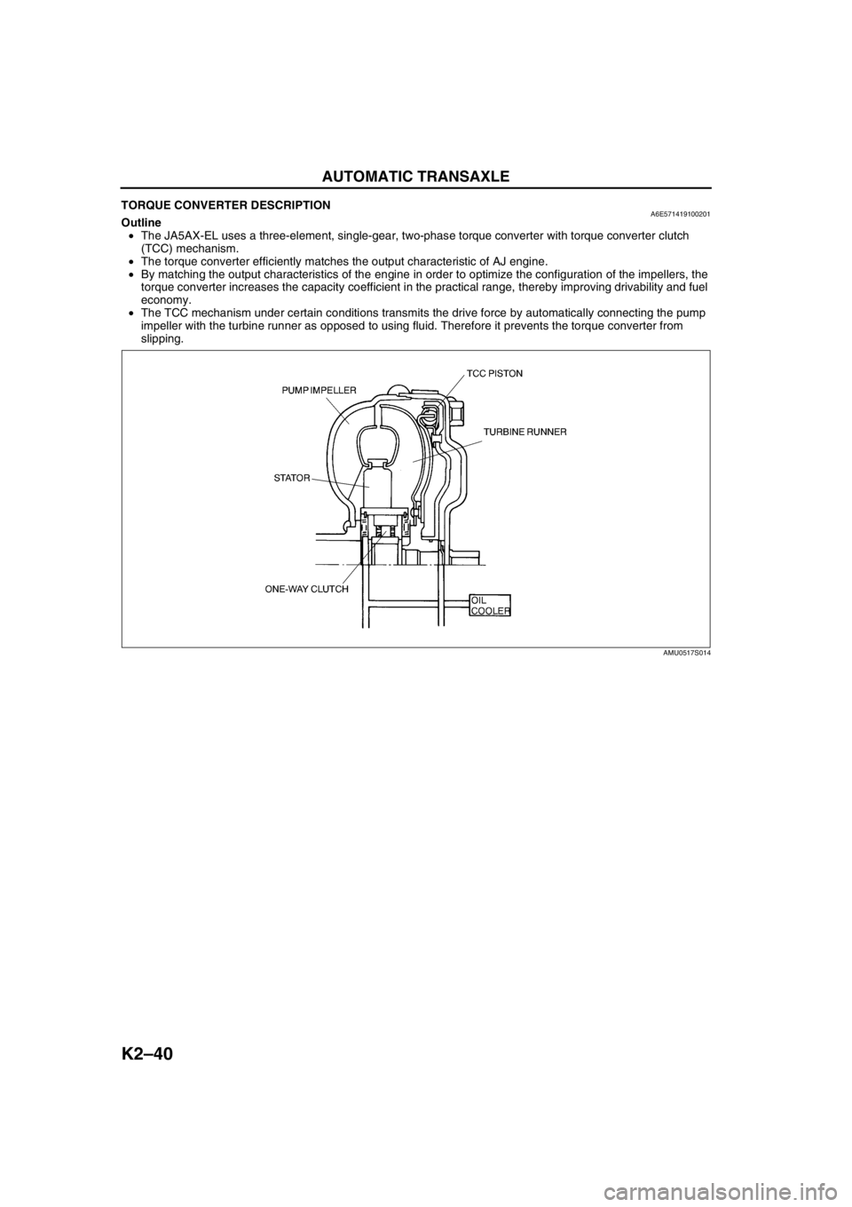
TORQUE CONVERTER DESCRIPTIONA6E571419100201Outline
•The JA5AX-EL uses a three-element, single-gear, two-phase torque converter with torque converter clutch
(TCC) mechanism.
•The torque converter efficiently matches the output characteristic of AJ engine.
•By matching the output characteristics of the engine in order to optimize the configuration of the impellers, the
torque converter increases the capacity coefficient in the practical range, thereby improving drivability and fuel
economy.
•The TCC mechanism under certain conditions transmits the drive force by automatically connecting the pump
impeller with the turbine runner as opposed to using fluid. Therefore it prevents the torque converter from
slipping.
End Of Sie
AMU0517S014
Page 474 of 909
AUTOMATIC TRANSAXLE
K2–59
K2
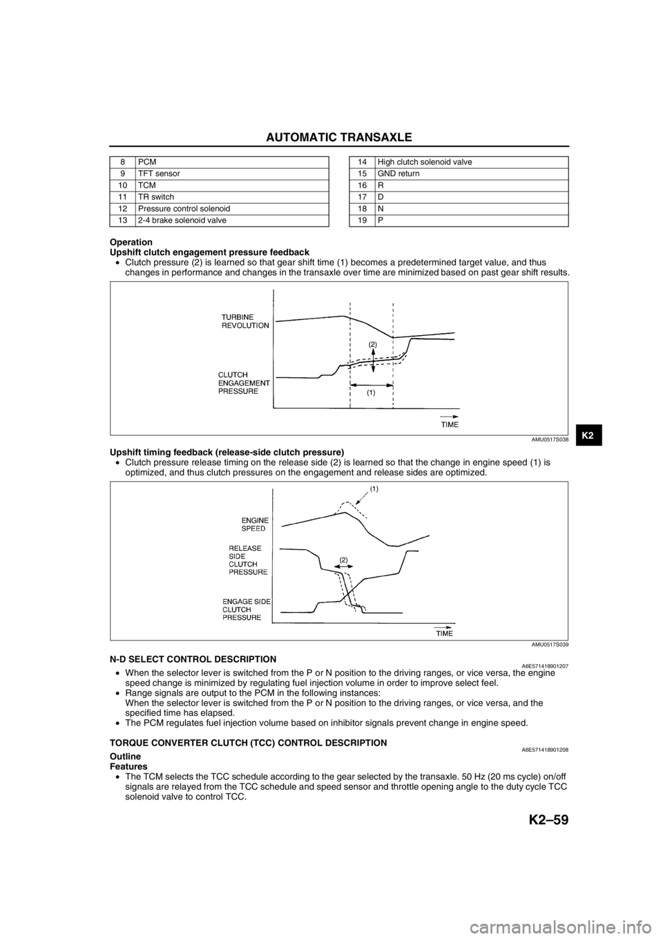
Operation
Upshift clutch engagement pressure feedback
•Clutch pressure (2) is learned so that gear shift time (1) becomes a predetermined target value, and thus
changes in performance and changes in the transaxle over time are minimized based on past gear shift results.
Upshift timing feedback (release-side clutch pressure)
•Clutch pressure release timing on the release side (2) is learned so that the change in engine speed (1) is
optimized, and thus clutch pressures on the engagement and release sides are optimized.
End Of SieN-D SELECT CONTROL DESCRIPTIONA6E571418901207•When the selector lever is switched from the P or N position to the driving ranges, or vice versa, the engine
speed change is minimized by regulating fuel injection volume in order to improve select feel.
•Range signals are output to the PCM in the following instances:
When the selector lever is switched from the P or N position to the driving ranges, or vice versa, and the
specified time has elapsed.
•The PCM regulates fuel injection volume based on inhibitor signals prevent change in engine speed.
End Of Sie
TORQUE CONVERTER CLUTCH (TCC) CONTROL DESCRIPTIONA6E571418901208Outline
Features
•The TCM selects the TCC schedule according to the gear selected by the transaxle. 50 Hz (20 ms cycle) on/off
signals are relayed from the TCC schedule and speed sensor and throttle opening angle to the duty cycle TCC
solenoid valve to control TCC.
8PCM
9 TFT sensor
10 TCM
11 TR switch
12 Pressure control solenoid
13 2-4 brake solenoid valve14 High clutch solenoid valve
15 GND return
16 R
17 D
18 N
19 P
AMU0517S038
AMU0517S039
Page 615 of 909

K2–200
TROUBLESHOOTING
Diagnostic procedure
End Of SieNO.25 ENGINE STALLS WHEN DRIVING AT SLOW SPEED OR STOPPINGA6E578001030228
Diagnostic procedure
End Of SieNO.26 STARTER DOES NOT WORKA6E578001030229
End Of SieNO.27 GEAR POSITION INDICATOR LIGHT DOES NOT ILLUMINATE IN M RANGEA6E578001030230
Diagnostic procedure
STEP INSPECTION ACTION
1•Go to symptom troubleshooting No.4
“Engine stalls-after start/at idle”.
(See Section F.)
•Is engine control system okay?Yes Go to next step.
No Repair or replace any defective parts according to
inspection results.
2•Remove torque converter.
•Inspect torque converter.
(See ATX Workshop Manual.)
•Is torque converter okay?Yes•Inspect for bend, damage or kinks of oil cooler line
pipes. If okay, overhaul control valve body and repair or
replace any defective parts.
(See ATX Workshop Manual.)
•If problem remains, replace or overhaul transaxle and
repair or replace any defective parts.
(See ATX Workshop Manual.)
No Replace torque converter.
3•Verify test results.
—If okay, return to diagnostic index to service any additional symptoms.
—If malfunction remains, inspect related Service Informations and perform repair or diagnosis.
—If vehicle repaired, troubleshooting completed.
—If vehicle not repaired or additional diagnostic information not available, replace TCM.
25 Engine stalls when driving at slow speeds or stopping
DESCRIPTION•Engine stalls when brake pedal depressed while driving at low speed or stopping.
POSSIBLE
CAUSE•Malfunction is on engine control side (e.g. Fuel injection control, IAC system)
Note
•Before following troubleshooting steps, make sure that Automatic Transaxle On-Board Diagnostic
and Automatic Transaxle Basic Inspection are conducted.
STEP INSPECTION ACTION
1•Go to symptom troubleshooting No.10 “Low
idle/stalls during deceleration”.
(See Section F.)
•Is engine control system okay?Yes Go to symptom troubleshooting No.24 “Engine stalls when
shifted to D range, or in R position”.
No Repair or replace any defective parts according to
inspection results.
2•Verify test results.
—If okay, return to diagnostic index to service any additional symptoms.
—If malfunction remains, inspect related Service Informations and perform repair or diagnosis.
—If vehicle repaired, troubleshooting completed.
—If vehicle not repaired or additional diagnostic information not available, replace TCM.
26Starter does not work
DESCRIPTION•Starter does not work even when P or N position.
POSSIBLE
CAUSE•Selector lever misadjustment.
•TR switch misadjustment.
•Open or short circuit in TR switch.
27 Gear position indicator light does not illuminate in M range
DESCRIPTION•Gear position indicator light in instrument cluster does not illuminate in M range and ignition switch at
on.
POSSIBLE
CAUSE•M range switch, gear position indicator light or related wiring harness malfunction.
Note
•Before following troubleshooting steps, make sure that Automatic Transaxle On-Board Diagnostic
and Automatic Transaxle Basic Inspection are conducted.
STEP INSPECTION ACTION
1•Are other indicator lights illuminated with
ignition switch on? Yes Go to next step.
No Inspect meter fuse.
Page 637 of 909
ELECTRONIC 4WD CONTROL SYSTEM
M–7
M
OUTLINEA6E632227100201Features
Improved off-road mobility, handling stability, operability, fuel economy and marketability
•An electronic 4WD control system, which automatically optimizes traction distribution to the front and rear
wheels, has been adopted.
Improved serviceability
•A self-diagnostic function has been adopted for the electronic 4WD control system.
Electronic 4WD control system outline
•The newly adopted electronic 4WD control system automatically and optimally controls drive torque distribution
for the front and rear wheels. Due to this off-road mobility, driving stability and fuel economy are improved.
•Based on the input signals from each sensor, the 4WD control modure (4WD CM) determines vehicle driving
and road conditions, and controls output current to the electronic control coupling (4WD solenoid) inside the
rear differential. This control allows for optimal distribution of the drive torque from the engine to the rear
wheels.
•Also, the 4WD CM automatically controls the 4WD, greatly reducing the load on the driver and improving
operability.
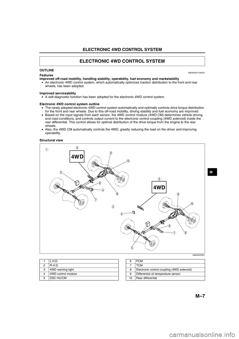
Structural view
.
ELECTRONIC 4WD CONTROL SYSTEM
87
5
4
3
6
9
8
7
5
4
3
10
6
1
2
9
10
A6E63222001
1L.H.D.
2 R.H.D.
3 4WD warning light
4 4WD control modure
5 DSC HU/CM6PCM
7TCM
8 Electronic control coupling (4WD solenoid)
9 Differential oil temperature sensor
10 Rear differential
Page 645 of 909
ELECTRONIC 4WD CONTROL SYSTEM
M–15
M
Operation
Normal control
•When starting off or accelerating during straight-ahead driving, torque transmitted to the rear wheels is
optimally controlled to ensure sufficient acceleration performance. Due to this, standing-start and acceleration
performance is improved.
•Also, in order to improve fuel economy when driving at a stable, consistent speed, torque transmitted to the
rear wheels is damped, and rear-wheel drive is controlled to maintain it close to that of the front wheels.
Tight cornering control
•When the 4WD CM determines, based on the four-wheel speed signal, that the vehicle is in tight cornering, it
reduces the torque transmitted to the rear wheels to avoid tight corner braking characteristics.
Integrated DSC control
•If a signal from the DSC HU/CM input to the 4WD CM indicates that ABS control is activated, the module
controls the torque transmitted to the rear wheels to prevent undue influence on ABS control.
•Also, when a coupling torque request signal is received from the DSC HU/CM, the module controls the torque
transmitted to the rear wheels to match the amount of requested torque.
Other control
•In case the rear differential oil temperature exceeds the specified amount, or when there is an unusually large
variation in the rotation speed of the front and rear wheels (ex. when trying to get unstuck), control is
temporarily suspended in order to protect the 4WD system. When this occurs the 4WD warning light flashes to
indicate the situation to the driver.
End Of Sie
CONTROLLER AREA NETWORK (CAN)A6E632227100207Outline
•The 4WD CM transmits/receives information using the CAN system. See Section T for detailed information
regarding the CAN system.
Operation
Transmitted information
•Coupling torque
•4WD system operating condition (warning light information)
Received information
•Four-wheel speed
•Throttle opening angle
•Engine speed
•ABS/DSC operating condition
•Gear position
•Selector lever position
•Coupling torque request
End Of Sie
Page 651 of 909

GENERAL PROCEDURES
M–21
M
PRECAUTION (FRONT AND REAR AXLE)A6E631001018201Wheel and Tire Removal/Installation
1. The removal and installation procedures for the wheels and tires are not mentioned in this section. When a
wheel is removed, tighten it to 88—118 N·m {9.0—12.0 kgf·m, 65.0—87.0 ft·lbf}
Brake Line Disconnection/Connection
Caution
•Brake fluid will damage painted surfaces. If brake fluid gets on a painted surface, wipe it off
immediately.
1. Tighten the brake pipe flare nut using the SST (49 0259 770B). Be sure to modify the brake pipe flare nut
tightening torque to allow for use of a torque wrench-SST combination.
2. If any brake line has been disconnected any time during the procedure, add brake fluid, bleed the brakes, and
inspect for leakage after the procedure has been completed.
Suspension Arm Removal/Installation
1. Tighten any part of the suspension that uses rubber bushings only after vehicle has been lowered and
unloaded.
Note
•Unloaded: Fuel tank is full. Engine coolant and engine oil are at specified level. Spare tire, jack, and tools
are in designated position.
Connector Disconnection
1. Disconnect the negative (-) battery cable before disconnecting connectors.
Electronic Control 4WD System Parts
1. After servicing the electronic control 4WD system parts, verify that no DTC has been stored. Clear any DTCs
remaining in the memory.
End Of Sie
GENERAL PROCEDURES
Page 741 of 909
P–8
DYNAMIC STABILITY CONTROL
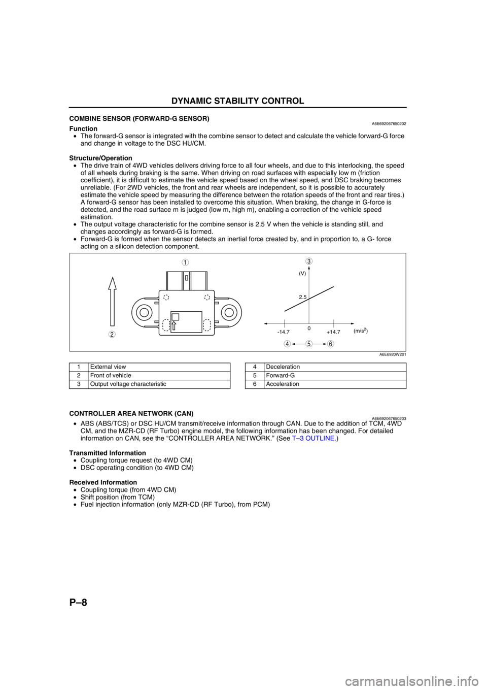
End Of SieCOMBINE SENSOR (FORWARD-G SENSOR)A6E692067650202Function
•The forward-G sensor is integrated with the combine sensor to detect and calculate the vehicle forward-G force
and change in voltage to the DSC HU/CM.
Structure/Operation
•The drive train of 4WD vehicles delivers driving force to all four wheels, and due to this interlocking, the speed
of all wheels during braking is the same. When driving on road surfaces with especially low m (friction
coefficient), it is difficult to estimate the vehicle speed based on the wheel speed, and DSC braking becomes
unreliable. (For 2WD vehicles, the front and rear wheels are independent, so it is possible to accurately
estimate the vehicle speed by measuring the difference between the rotation speeds of the front and rear tires.)
A forward-G sensor has been installed to overcome this situation. When braking, the change in G-force is
detected, and the road surface m is judged (low m, high m), enabling a correction of the vehicle speed
estimation.
•The output voltage characteristic for the combine sensor is 2.5 V when the vehicle is standing still, and
changes accordingly as forward-G is formed.
•Forward-G is formed when the sensor detects an inertial force created by, and in proportion to, a G- force
acting on a silicon detection component.
.
End Of Sie
CONTROLLER AREA NETWORK (CAN)A6E692067650203•ABS (ABS/TCS) or DSC HU/CM transmit/receive information through CAN. Due to the addition of TCM, 4WD
CM, and the MZR-CD (RF Turbo) engine model, the following information has been changed. For detailed
information on CAN, see the “CONTROLLER AREA NETWORK.” (See T–3 OUTLINE.)
Transmitted Information
•Coupling torque request (to 4WD CM)
•DSC operating condition (to 4WD CM)
Received Information
•Coupling torque (from 4WD CM)
•Shift position (from TCM)
•Fuel injection information (only MZR-CD (RF Turbo), from PCM)
End Of Sie
(V)
2.5
-14.70
+14.7(m/s
2)
45
3
6
2
1
A6E6920W201
1 External view
2 Front of vehicle
3 Output voltage characteristic4 Deceleration
5 Forward-G
6 Acceleration