ESP MAZDA 6 2002 Workshop Manual Suplement
[x] Cancel search | Manufacturer: MAZDA, Model Year: 2002, Model line: 6, Model: MAZDA 6 2002Pages: 909, PDF Size: 17.16 MB
Page 3 of 909

WARNING
Servicing a vehicle can be dangerous. If you have not received
service-related training, the risks of injury, property damage, and
failure of servicing increase. The recommended servicing procedures
for the vehicle in this workshop manual were developed with
Mazda-trained technicians in mind. This manual may be useful to
non-Mazda trained technicians, but a technician with our
service-related training and experience will be at less risk when
performing service operations. However, all users of this manual are
expected to at least know general safety procedures.
This manual contains "Warnings" and "Cautions" applicable to risks
not normally encountered in a general technician's experience.
They should be followed to reduce the risk of injury and the risk that
improper service or repair may damage the vehicle or render it unsafe.
It is also important to understand that the "Warnings" and "Cautions"
are not exhaustive. It is impossible to warn of all the hazardous
consequences that might result from failure to follow the procedures.
The procedures recommended and described in this manual are
effective methods of performing service and repair. Some require tools
specifically designed for a specific purpose. Persons using procedures
and tools which are not recommended by Mazda Motor Corporation
must satisfy themselves thoroughly that neither personal safety nor
safety of the vehicle will be jeopardized.
The contents of this manual, including drawings and specifications, are
the latest available at the time of printing, and
Mazda Motor Corporation
reserves the right to change the vehicle designs and alter the contents
of this manual without notice and without incurring obligation.
Parts should be replaced with genuine Mazda replacement parts or
with parts which match the quality of genuine Mazda replacement
parts. Persons using replacement parts of lesser quality than that of
genuine Mazda replacement parts must satisfy themselves thoroughly
that neither personal safety nor safety of the vehicle will be
jeopardized.
Mazda Motor Corporation is not responsible for any problems which
may arise from the use of this manual. The cause of such problems
includes but is not limited to insufficient service-related training, use of
improper tools, use of replacement parts of lesser quality than that of
genuine Mazda replacement parts, or not being aware of any revision
of this manual.
Page 113 of 909
FUEL SYSTEM
F1–25
F1
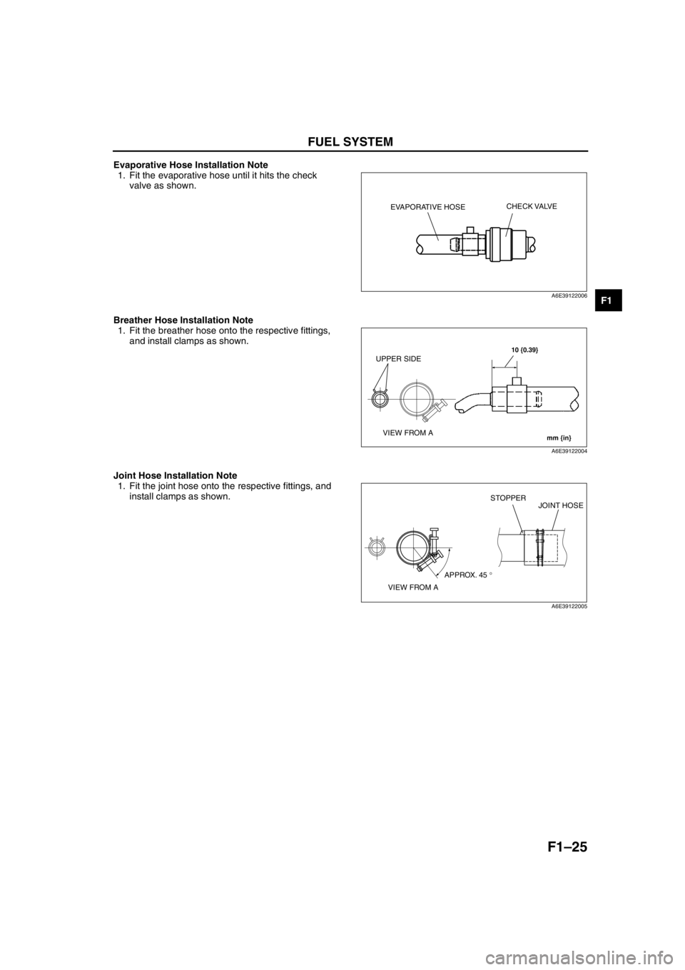
Evaporative Hose Installation Note
1. Fit the evaporative hose until it hits the check
valve as shown.
Breather Hose Installation Note
1. Fit the breather hose onto the respective fittings,
and install clamps as shown.
Joint Hose Installation Note
1. Fit the joint hose onto the respective fittings, and
install clamps as shown.
End Of Sie
EVAPORATIVE HOSECHECK VALVE
A6E39122006
10 {0.39}
mm {in}
UPPER SIDE
VIEW FROM A
A6E39122004
VIEW FROM AAPPROX. 45 °STOPPER
JOINT HOSE
A6E39122005
Page 175 of 909
CONTROL SYSTEM
F2–23
F2
CRUISE CONTROL SYSTEMA6E404018881205Outline
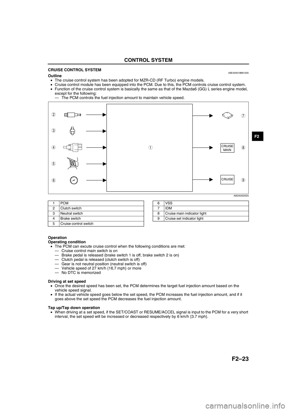
•The cruise control system has been adopted for MZR-CD (RF Turbo) engine models.
•Cruise control module has been equipped into the PCM. Due to this, the PCM controls cruise control system.
•Function of the cruise control system is basically the same as that of the Mazda6 (GG) L series engine model,
except for the following:
—The PCM controls the fuel injection amount to maintain vehicle speed.
.
Operation
Operating condition
•The PCM can excute cruise control when the following conditions are met:
—Cruise control main switch is on
—Brake pedal is released (brake switch 1 is off, brake switch 2 is on)
—Clutch pedal is released (clutch switch is off)
—Gear is not neutral position (neutral switch is off)
—Vehicle speed of 27 km/h {16.7 mph} or more
—No DTC is memorized
Driving at set speed
•Once the desired speed has been set, the PCM determines the target fuel injection amount based on the
vehicle speed signal.
•If the actual vehicle speed goes below the set speed, the PCM increases the fuel injection amount, and if it
goes above the set speed the PCM decreases the fuel injection amount.
Tap up/Tap down operation
•When driving at a set speed, if the SET/COAST or RESUME/ACCEL signal is input to the PCM for a very short
interval, the set speed will be increased or decreased respectively by 6 km/h {3.7 mph}.
End Of Sie
CRUISE
MAIN
CRUISE
8
7
5
4
3
6
1
2
9
A6E40402025
1PCM
2 Clutch switch
3 Neutral switch
4 Brake switch
5 Cruise control switch6 VSS
7IDM
8 Cruise main indicator light
9 Cruise set indicator light
Page 186 of 909
F2–34
ENGINE TUNE-UP
ENGINE TUNE-UP PREPARATIONA6E4008020002011. Start the engine and warm up completely.
2. Verify that the gear is in neutral position.
3. Verify that the accelerator pedal is released.
4. Turn off the A/C switch.
5. Turn off all electrical loads.
6. Verify that no DTC is present.
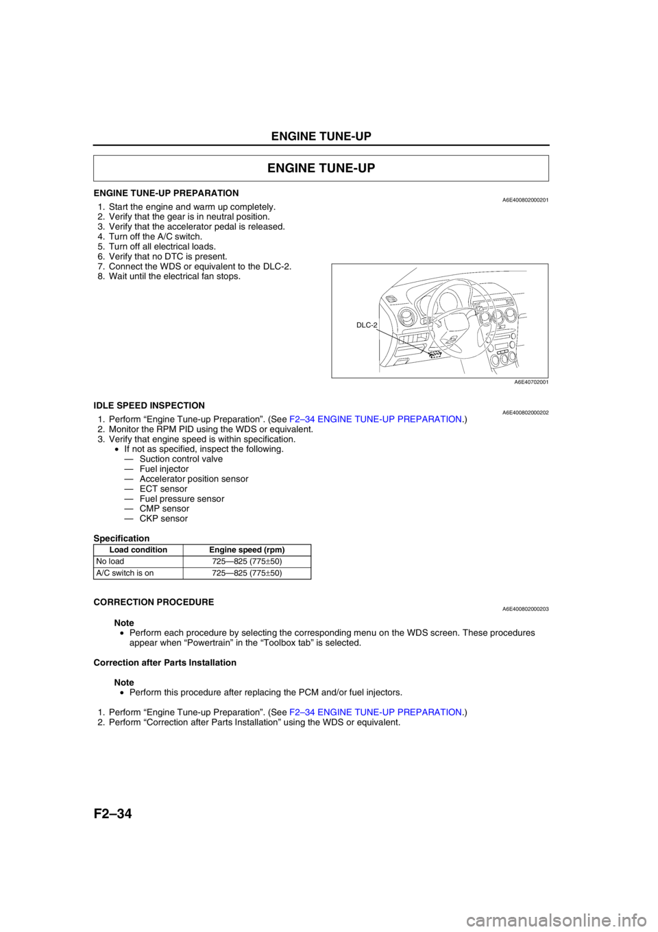
7. Connect the WDS or equivalent to the DLC-2.
8. Wait until the electrical fan stops.
End Of Sie
IDLE SPEED INSPECTIONA6E4008020002021. Perform “Engine Tune-up Preparation”. (See F2–34 ENGINE TUNE-UP PREPARATION.)
2. Monitor the RPM PID using the WDS or equivalent.
3. Verify that engine speed is within specification.
•If not as specified, inspect the following.
—Suction control valve
—Fuel injector
—Accelerator position sensor
—ECT sensor
—Fuel pressure sensor
—CMP sensor
—CKP sensor
Specification
End Of Sie
CORRECTION PROCEDUREA6E400802000203
Note
•Perform each procedure by selecting the corresponding menu on the WDS screen. These procedures
appear when “Powertrain” in the “Toolbox tab” is selected.
Correction after Parts Installation
Note
•Perform this procedure after replacing the PCM and/or fuel injectors.
1. Perform “Engine Tune-up Preparation”. (See F2–34 ENGINE TUNE-UP PREPARATION.)
2. Perform “Correction after Parts Installation” using the WDS or equivalent.
ENGINE TUNE-UP
DLC-2
A6E40702001
Load condition Engine speed (rpm)
No load 725—825 (775±50)
A/C switch is on 725—825 (775±50)
Page 200 of 909
F2–48
FUEL SYSTEM
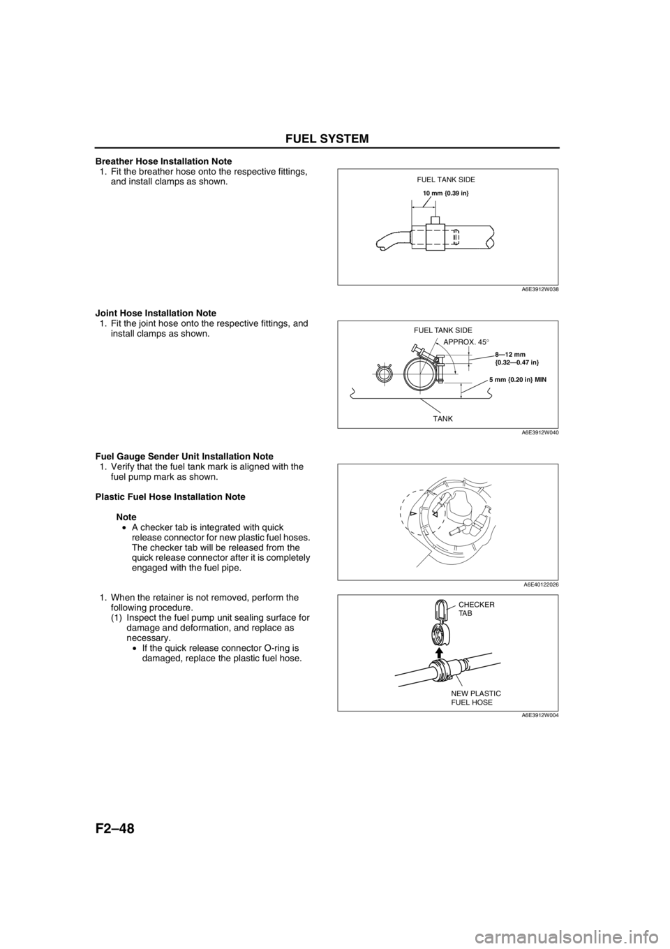
Breather Hose Installation Note
1. Fit the breather hose onto the respective fittings,
and install clamps as shown.
Joint Hose Installation Note
1. Fit the joint hose onto the respective fittings, and
install clamps as shown.
Fuel Gauge Sender Unit Installation Note
1. Verify that the fuel tank mark is aligned with the
fuel pump mark as shown.
Plastic Fuel Hose Installation Note
Note
•A checker tab is integrated with quick
release connector for new plastic fuel hoses.
The checker tab will be released from the
quick release connector after it is completely
engaged with the fuel pipe.
1. When the retainer is not removed, perform the
following procedure.
(1) Inspect the fuel pump unit sealing surface for
damage and deformation, and replace as
necessary.
•If the quick release connector O-ring is
damaged, replace the plastic fuel hose.
FUEL TANK SIDE
10 mm {0.39 in}
A6E3912W038
8—12 mm
{0.32—0.47 in}
5 mm {0.20 in} MIN
TANK
APPROX. 45° FUEL TANK SIDE
A6E3912W040
A6E40122026
CHECKER
TA B
NEW PLASTIC
FUEL HOSE
A6E3912W004
Page 235 of 909
CONTROL SYSTEM
F2–83
F2
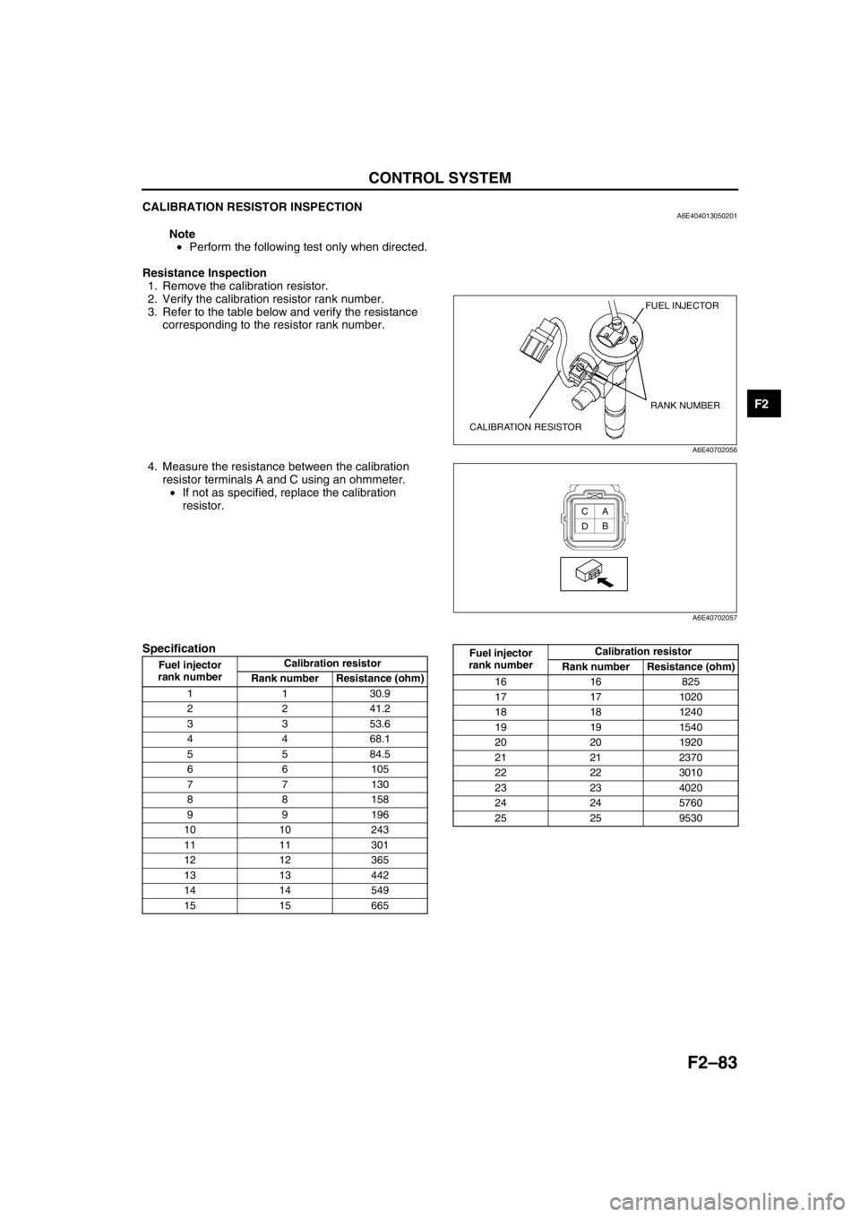
CALIBRATION RESISTOR INSPECTIONA6E404013050201
Note
•Perform the following test only when directed.
Resistance Inspection
1. Remove the calibration resistor.
2. Verify the calibration resistor rank number.
3. Refer to the table below and verify the resistance
corresponding to the resistor rank number.
4. Measure the resistance between the calibration
resistor terminals A and C using an ohmmeter.
•If not as specified, replace the calibration
resistor.
Specification
FUEL INJECTOR
CALIBRATION RESISTORRANK NUMBER
A6E40702056
A
B C
D
A6E40702057
Fuel injector
rank numberCalibration resistor
Rank number Resistance (ohm)
1 1 30.9
2 2 41.2
3 3 53.6
4 4 68.1
5 5 84.5
66105
77130
88158
99196
10 10 243
11 11 301
12 12 365
13 13 442
14 14 549
15 15 665
16 16 825
17 17 1020
18 18 1240
19 19 1540
20 20 1920
21 21 2370
22 22 3010
23 23 4020
24 24 5760
25 25 9530 Fuel injector
rank numberCalibration resistor
Rank number Resistance (ohm)
Page 419 of 909

K2–4
AUTOMATIC TRANSAXLE
Bold frames:New specifications
End Of Sie
OUTLINEA6E571401030201•Adopted new JA5AX-EL automatic transaxle.
•Newly designed FF type five-speed automatic transaxle.
—Use of 3 sets of planetary gears, and a wider gear ratio setting realizes improvement of acceleration-from-
standing-start performance, fuel economy, and quietness. Also, by placement of two sets of planetary gears
in parallel with one set, the automatic transaxle is more compact.
•Adopted 2-4 brake clutch.
—Adopted a wet-type, multi-plate 2-4 brake clutch instead of the 2-4 brake band used in the past, for
smoother gear switching performance.
•Adopted centrifugal balance clutch
—The newly adopted centrifugal balance clutch pushes the clutch piston forcefully to low and high clutch by
centrifugal hydraulic pressure for smoother gear switching with batter response.
•Adopted controller area network (CAN)
—By adopting CAN, The TCM is always in contact with other computers in the car and controls the automatic
transaxle properly. This has also made troubleshooting diagnosis easier for the entire vehicle.
•Solenoid, sensor
—Adoption of four duty-type solenoids, five ON-OFF type solenoids, and three revolving sensors realizes
finer, more expedient control of gear shifting performance.
•Adoption of revers inhibit control
—If the reverse position is selected by mistake while driving in forward motion, the reverse inhibit control
system will cancel the operation electronically and set the position to neutral as a safety enhancement.
Outline of Operation
•The operation of the electronic automatic transaxle is classified into three systems: the electronic control
system, the hydraulic pressure control system, and the powertrain system (includes the torque converter
system.)
Electronic control system
•According to the signals from the switches and sensors in the input system, the TCM outputs the signal
which matches the present driving condition to the ON/OFF type solenoids and the duty-cycle type
solenoids in the hydraulic pressure control system.
Hydraulic pressure control system
•According to the signals from the TCM, each solenoid operates to switch the hydraulic passages in the
control valve body and controls the clutch engagement pressure.
•The line pressure is adjusted by the duty-cycle type pressure control solenoid. The hydraulic passages
are switched by the ON/OFF type solenoids and the clutch engagement pressure is controlled by the
duty-cycle type solenoids.
Powertrain system
•The driving force from the engine is transmitted through the torque converter to the transaxle.
•The transmitted driving force operates each clutch and brake according to the clutch engagement
pressure from the duty-cycle type solenoid, and the planetary gears change the gear ratio to the
optimal driving force. The changed driving force is transmitted through the differential to the axle shaft
and then the tires.
AUTOMATIC TRANSAXLE
Page 479 of 909
K2–64
AUTOMATIC TRANSAXLE
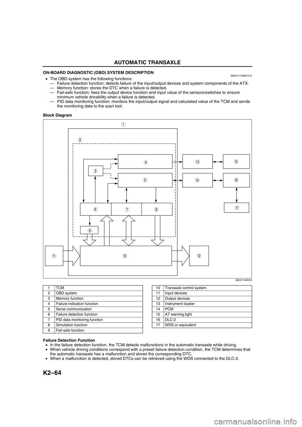
ON-BOARD DIAGNOSTIC (OBD) SYSTEM DESCRIPTIONA6E571418901210•The OBD system has the following functions:
—Failure detection function: detects failure of the input/output devices and system components of the ATX.
—Memory function: stores the DTC when a failure is detected.
—Fail-safe function: fixes the output device function and input value of the sensors/switches to ensure
minimum vehicle drivability when a failure is detected.
—PID data monitoring function: monitors the input/output signal and calculated value of the TCM and sends
the monitoring data to the scan tool.
Block Diagram
.
Failure Detection Function
•In the failure detection function, the TCM detects malfunctions in the automatic transaxle while driving.
•When vehicle driving conditions correspond with a preset failure detection condition, the TCM determines that
the automatic transaxle has a malfunction and stores the corresponding DTC.
•When a malfunction is detected, stored DTCs can be retrieved using the WDS connected to the DLC-2.
9
87
5
4
3
1
2
10
17
15
1614
13
1112
6
A6E5714W023
1TCM
2 OBD system
3 Memory function
4 Failure indication function
5 Serial communication
6 Failure detection function
7 PID data monitoring function
8 Simulation function
9 Fail-safe function10 Transaxle control system
11 Input devices
12 Output devices
13 Instrument cluster
14 PCM
15 AT warning light
16 DLC-2
17 WDS or equivalent
Page 532 of 909
AUTOMATIC TRANSAXLE SHIFT MECHANISM
K2–117
K2
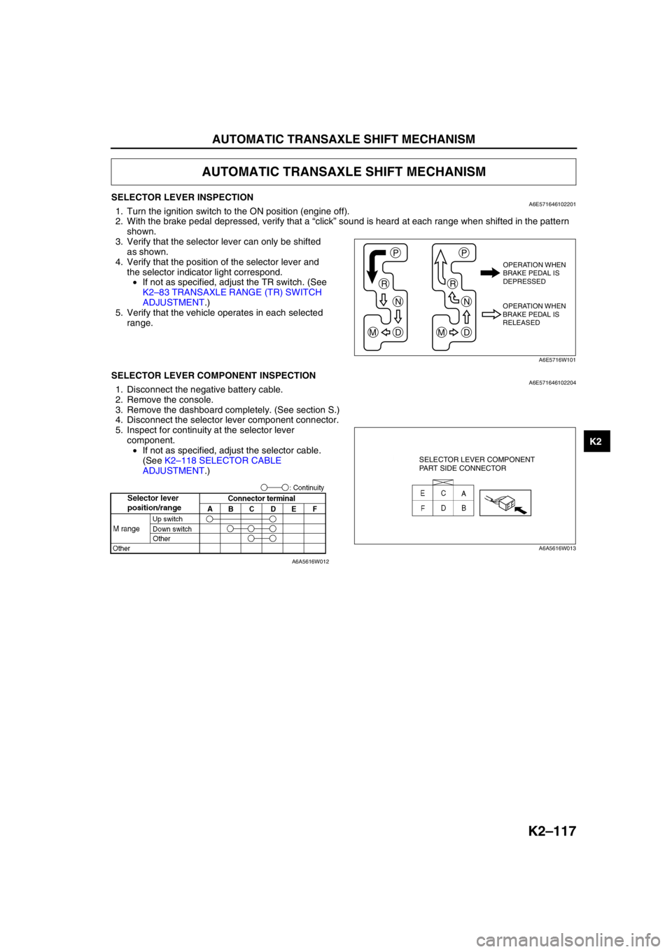
SELECTOR LEVER INSPECTIONA6E5716461022011. Turn the ignition switch to the ON position (engine off).
2. With the brake pedal depressed, verify that a “click” sound is heard at each range when shifted in the pattern
shown.
3. Verify that the selector lever can only be shifted
as shown.
4. Verify that the position of the selector lever and
the selector indicator light correspond.
•If not as specified, adjust the TR switch. (See
K2–83 TRANSAXLE RANGE (TR) SWITCH
ADJUSTMENT.)
5. Verify that the vehicle operates in each selected
range.
End Of SieSELECTOR LEVER COMPONENT INSPECTIONA6E5716461022041. Disconnect the negative battery cable.
2. Remove the console.
3. Remove the dashboard completely. (See section S.)
4. Disconnect the selector lever component connector.
5. Inspect for continuity at the selector lever
component.
•If not as specified, adjust the selector cable.
(See K2–118 SELECTOR CABLE
ADJUSTMENT.)
End Of Sie
AUTOMATIC TRANSAXLE SHIFT MECHANISM
P
R
N
DM
P
R
N
DM
OPERATION WHEN
BRAKE PEDAL IS
DEPRESSED
OPERATION WHEN
BRAKE PEDAL IS
RELEASED
A6E5716W101
SELECTOR LEVER COMPONENT
PART SIDE CONNECTOR
A6A5616W013
A6A5616W012
Page 597 of 909
K2–182
TROUBLESHOOTING
FOREWORDA6E578001030201•Refer to Section GI and thoroughly read and understand the basic flow of troubleshooting in order to properly
perform the procedure.
End Of Sie
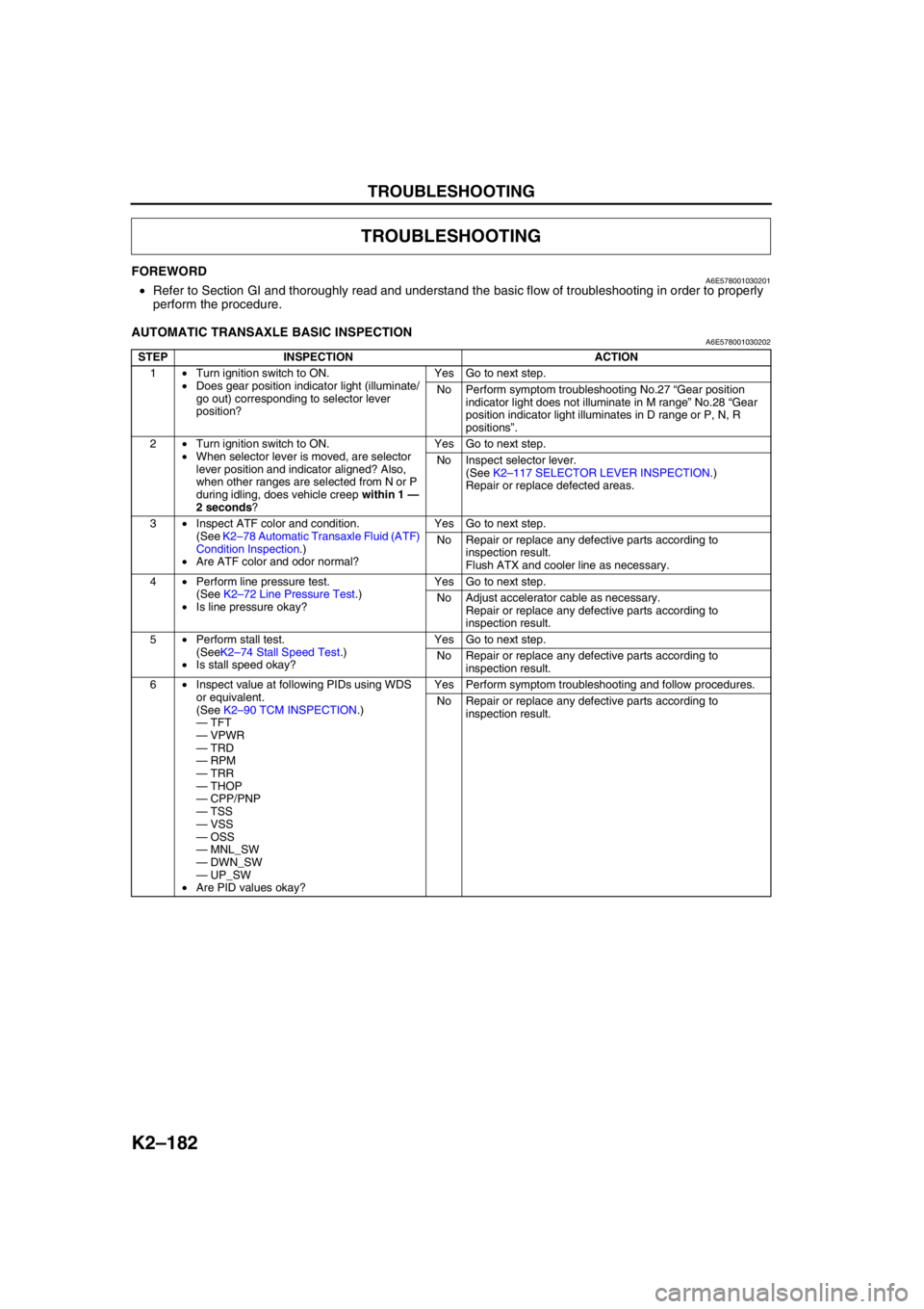
AUTOMATIC TRANSAXLE BASIC INSPECTIONA6E578001030202
End Of Sie
TROUBLESHOOTING
STEP INSPECTION ACTION
1•Turn ignition switch to ON.
•Does gear position indicator light (illuminate/
go out) corresponding to selector lever
position?Yes Go to next step.
No Perform symptom troubleshooting No.27 “Gear position
indicator light does not illuminate in M range” No.28 “Gear
position indicator light illuminates in D range or P, N, R
positions”.
2•Turn ignition switch to ON.
•When selector lever is moved, are selector
lever position and indicator aligned? Also,
when other ranges are selected from N or P
during idling, does vehicle creep within 1 —
2 seconds?Yes Go to next step.
No Inspect selector lever.
(See K2–117 SELECTOR LEVER INSPECTION.)
Repair or replace defected areas.
3•Inspect ATF color and condition.
(See K2–78 Automatic Transaxle Fluid (ATF)
Condition Inspection.)
•Are ATF color and odor normal?Yes Go to next step.
No Repair or replace any defective parts according to
inspection result.
Flush ATX and cooler line as necessary.
4•Perform line pressure test.
(See K2–72 Line Pressure Test.)
•Is line pressure okay?Yes Go to next step.
No Adjust accelerator cable as necessary.
Repair or replace any defective parts according to
inspection result.
5•Perform stall test.
(SeeK2–74 Stall Speed Test.)
•Is stall speed okay?Yes Go to next step.
No Repair or replace any defective parts according to
inspection result.
6•Inspect value at following PIDs using WDS
or equivalent.
(See K2–90 TCM INSPECTION.)
—TFT
—VPWR
—TRD
—RPM
—TRR
—THOP
—CPP/PNP
—TSS
—VSS
—OSS
—MNL_SW
—DWN_SW
—UP_SW
•Are PID values okay?Yes Perform symptom troubleshooting and follow procedures.
No Repair or replace any defective parts according to
inspection result.