cruise control MAZDA 6 2002 Suplement Owner's Manual
[x] Cancel search | Manufacturer: MAZDA, Model Year: 2002, Model line: 6, Model: MAZDA 6 2002Pages: 909, PDF Size: 17.16 MB
Page 305 of 909

ON-BOARD DIAGNOSTIC
F2–153
F2
End Of Sie
2INSPECT POOR CONNECTION OF CRUISE
CONTROL SWITCH CONNECTOR
•Turn engine switch to OFF.
•Inspect for poor connection (damaged, pulled-
out terminals, corrosion, etc.).
•Is there any malfunction?Yes Repair or replace suspected terminal, go to Step 9.
No Go to next step.
3INSPECT CRUISE CONTROL SWITCH SIGNAL
CIRCUIT FOR SHORT TO GND
•Turn engine switch to OFF.
•Inspect continuity between cruise control
switch terminal B and body GND.
•Is there continuity?Yes Repair or replace harness for short to GND, go to Step 9.
No Go to next step.
4INSPECT CRUISE CONTROL SWITCH CIRCUIT
FOR SHORT WITH EACH OTHER
•Turn engine switch to OFF.
•Inspect continuity between cruise control
switch terminals B and C.
•Is there continuity?Yes Repair or replace harness for short with each other, go to
Step 9.
No Go to next step.
5INSPECT CRUISE CONTROL SWITCH SIGNAL
CIRCUIT FOR OPEN
•Turn engine switch to ON. (Engine OFF)
•Inspect voltage at cruise control switch terminal
B (harness side).
•Is voltage below 1.0 V?Yes Repair or replace harness for open, go to Step 9.
No Go to next step.
6INSPECT CRUISE CONTROL SWITCH
•Inspect cruise control switch.
•Is there any malfunction?Yes Replace cruise control switch, go to Step 9.
No Go to next step.
7INSPECT POOR CONNECTION OF PCM
CONNECTOR
•Turn engine switch to OFF.
•Inspect for poor connection (damaged, pulled-
out terminals, corrosion, etc.).
•Is there any malfunction?Yes Repair or replace suspected terminal, go to Step 9.
No Go to next step.
8INSPECT CRUISE CONTROL SWITCH GND
CIRCUIT FOR OPEN
•Turn engine switch to OFF.
•Inspect continuity between cruise control
switch terminal C and PCM terminal 91.
•Is there continuity?Yes Go to next step.
No Repair or replace harness for open, go to next step.
9VERIFY TROUBLESHOOTING OF DTC P0564
COMPLETED
•Make sure to reconnect all disconnected
connectors.
•Clear DTC from PCM memory using WDS or
equivalent.
•Start engine.
•Is same DTC present?Yes Replace PCM, go to next step.
(See F2–64 PCM REMOVAL/INSTALLATION)
No Go to next step.
10VERIFY AFTER REPAIR PROCEDURE
•Perform “After Repair Procedure”.
(See F2–86 AFTER REPAIR PROCEDURE)
•Is there any DTC present?Yes Go to applicable DTC inspection.
(See F2–87 DTC TABLE)
No Troubleshooting completed. STEP INSPECTION ACTION
Page 321 of 909

TROUBLESHOOTING
F2–169
F2
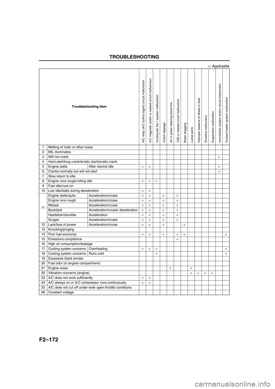
×: Applicable
Troubleshooting item
1 Melting of main or other fuses
2 MIL illuminates×× × ×
3 Will not crank
4 Hard start/long crank/erratic start/erratic crank×× ×××××××
5 Engine stalls After start/at idle×× ×××××××
6 Cranks normally but will not start×× ×××××××
7 Slow return to idle××××××××
8 Engine runs rough/rolling idle×××××××××
9 Fast idle/runs on×
10 Low idle/stalls during deceleration××××××××××
11Engine stalls/quits Acceleration/cruise× × ×××××××
Engine runs rough Acceleration/cruise× ××××××××××
Misses Acceleration/cruise× ××××××××××
Buck/jerk Acceleration/cruise/ deceleration× ××××××××××
Hesitation/stumble Acceleration× ××××××××××
Surges Acceleration/cruise× ×× ×××××××
12 Lack/loss of power Acceleration/cruise××× ×××××××××
13 Knocking/pinging××××× ××× × ×
14 Poor fuel economy××× ×××××× ×
15 Emissions compliance×××××××××××××
16 High oil consumption/leakage×
17 Cooling system concerns Overheating×
18 Cooling system concerns Runs cold
19 Excessive black smoke××× × ××× ×××
20 Fuel odor (in engine compartment)××
21 Engine noise× ××× ×
22 Vibration concerns (engine)
23 A/C does not work sufficiently
24 A/C always on or A/C compressor runs continuously
25 A/C does not cut off under wide open throttle conditions
26 Constant voltage
Turbocharger malfunctionCarge air cooler malfunctionVBC system malfunctionGlow system malfunctionIncorrect fuel injection timingIncorrect idle speedCKP sensor is damaged (e.g.: open or short circuits)CKP sensor pulse wheel is damagedImproper gap between CKP sensor and pulse wheelSupply pump malfunctionSuction control valve malfunctionFuel pressure limiter malfunctionFuel line restriction or clogging
Page 323 of 909

TROUBLESHOOTING
F2–171
F2
×: Applicable
Troubleshooting item
1 Melting of main or other fuses
2 MIL illuminates×××××× × ×××
3 Will not crank
4 Hard start/long crank/erratic start/erratic crank×× ×× ×
5 Engine stalls After start/at idle×× × × × ××
6 Cranks normally but will not start×× ×
7 Slow return to idle××× × × ×××
8 Engine runs rough/rolling idle××× × × ××××
9 Fast idle/runs on×××
10 Low idle/stalls during deceleration××× × × ××××
11Engine stalls/quits Acceleration/cruise× × × × ××××
Engine runs rough Acceleration/cruise××× × × ××××
Misses Acceleration/cruise× × × × ××××
Buck/jerk Acceleration/cruise/ deceleration× ×××× × ××××
Hesitation/stumble Acceleration× ×××× × ××××
Surges Acceleration/cruise× ×××× × ××××
12 Lack/loss of power Acceleration/cruise× ×××× × ××××
13 Knocking/pinging××××× ×
14 Poor fuel economy× ×××× ×××
15 Emissions compliance×××××× × ×××
16 High oil consumption/leakage
17 Cooling system concerns Overheating×
18 Cooling system concerns Runs cold
19 Excessive black smoke×× ×
20 Fuel odor (in engine compartment)×
21 Engine noise××××× ×
22 Vibration concerns (engine)×× ××××
23 A/C does not work sufficiently×
24 A/C always on or A/C compressor runs continuously
25 A/C does not cut off under wide open throttle conditions××
26 Constant voltage××××× ×
PCM control relay malfunctionECT sensor or related circuit malfunctionNeutral switch or related circuit malfunctionMAF/IAT sensor or related circuit malfunctionIAT sensor No.2 or related circuit malfunctionBoost sensor or related circuit malfunctionAccelerator position sensor or related circuit malfunctionAccelerator position sensor misadjustment
(including looseness)Idle switch or related circuit malfunctionIdle switch misadjustment (including looseness)Fuel pressure sensor or related circuit malfunctionImproper refrigerant charging amount
Page 324 of 909

F2–172
TROUBLESHOOTING
×: Applicable
End Of Sie
Troubleshooting item
1 Melting of main or other fuses
2 MIL illuminates
3 Will not crank×
4 Hard start/long crank/erratic start/erratic crank
5 Engine stalls After start/at idle×× ×
6 Cranks normally but will not start×
7 Slow return to idle
8 Engine runs rough/rolling idle×××
9 Fast idle/runs on
10 Low idle/stalls during deceleration××
11Engine stalls/quits Acceleration/cruise××××
Engine runs rough Acceleration/cruise××××
Misses Acceleration/cruise××××
Buck/jerk Acceleration/cruise/ deceleration××××
Hesitation/stumble Acceleration××××
Surges Acceleration/cruise××××
12 Lack/loss of power Acceleration/cruise×× × ×
13 Knocking/pinging
14 Poor fuel economy××××× ×
15 Emissions compliance×
16 High oil consumption/leakage
17 Cooling system concerns Overheating××× ×
18 Cooling system concerns Runs cold××
19 Excessive black smoke
20 Fuel odor (in engine compartment)
21 Engine noise××
22 Vibration concerns (engine)××××
23 A/C does not work sufficiently××
24 A/C always on or A/C compressor runs continuously××
25 A/C does not cut off under wide open throttle conditions
26 Constant voltage
A/C relay (A/C control siganl) circuit malfunctionA/C magnetic clutch or related circuit malfunctionCooling fan No.1 system malfunctionClutch slippageAir in power steering fuluid lineVSS or related circuit malfunctionBrake draggingLoose partsImproper balance of wheel or tiresDriveline malfunctionSuspension malfunctionImmobilizer system and/or circuit malfunctionCoolant heater system malfunction
Page 344 of 909

F2–192
TROUBLESHOOTING
End Of Sie
NO.11 ENGINE STALLS/QUITS, ENGINE RUNS ROUGH, MISSES, BUCK/JERK, HESITATION/STUMBLE,
SURGES
A6E408018881213
17 Inspect IDM.
(See F2–84 INJECTOR DRIVER MODULE
(IDM) INSPECTION)
Is IDM okay?Yes Remove and inspect supply pump and common rail.
No Repair or replace as necessary.
18 Verify test results.
•If okay, return to diagnostic index to service any additional symptoms.
•If malfunction remains, replace PCM. (See F2–64 PCM REMOVAL/INSTALLATION) STEP INSPECTION RESULTS ACTION
11ENGINE STALLS/QUITS, ENGINE RUNS ROUGH, MISSES, BUCK/JERK, HESITATION/STUMBLE,
SURGES
DESCRIPTION•Engine stops unexpectedly at beginning of acceleration or during cruise.
•Engine stops unexpectedly while cruising.
•Engine speed fluctuates during acceleration or cruising.
•Engine misses during acceleration or cruising.
•Vehicle bucks/jerks during acceleration, during or deceleration.
•Momentary pause at beginning of acceleration or during acceleration.
•Momentary minor irregularity in engine output.
POSSIBLE
CAUSE•Poor fuel quality
•Glow system malfunction
•Air leakage from intake-air system
•Intake-air system restriction or clogging
•Engine overheating
•A/C system improper operation
•Turbocharger malfunction
•Variable swirl control (VSC) system malfunction
•EGR system malfunction
•Neutral switch or related circuit malfunction
•Cooling fan No.1 or cooling fan No.2 seat are improper
•Fuel line clogging or restriction
•Fuel filter clogging or restriction
•Incorrect fuel injection timing
•Erratic signal from CKP sensor
•Erratic signal from CMP sensor
•ECT sensor or related circuit malfunction
•Boost sensor or related circuit malfunction
•Accelerator position sensor or related circuit malfunction
•Idle switch or related circuit malfunction
•MAF/IAT sensor or related circuit malfunction
•IAT sensor No.2 or related circuit malfunction
•VSS or related circuit malfunction
•Incorrect adjustment accelerator position sensor and/or idle switch
•Incorrect idle speed
•Inadequate fuel pressure
•Fuel pressure sensor or related circuit malfunction
•Suction control valve malfunction (built-in supply pump)
•Fuel pressure limiter malfunction (built-in common rail)
•Supply pump malfunction
•Fuel injector malfunction
•Low engine compression
•Improper valve timing
•Exhaust system and/or catalyst converter restriction
•Clutch slippage
•IDM or related circuit malfunction
Warning
The following troubleshooting flow chart contains the fuel system diagnosis and repair
procedures. Read the following warnings before performing the fuel system services:
•Fuel vapor is hazardous. It can easily ignite, causing serious injury and damage. Always keep
sparks and flames away from fuel.
•Fuel line spills and leakage are dangerous. Fuel can ignite and cause serious injury or death
and damage. Fuel can also irritate skin and eyes. To prevent this, always complete “BEFORE
REPAIR PROCEDURE” and “AFTER REPAIR PROCEDURE” described in this manual.
Page 347 of 909

TROUBLESHOOTING
F2–195
F2
NO.12 LACK/LOSS OF POWER-ACCELERATION/CRUISEA6E408018881214
Diagnostic Procedure
12 LACK/LOSS OF POWER-ACCELERATION CRUISE
DESCRIPTION•Performance is poor under load (e.g., power down when climbing hills).
POSSIBLE
CAUSE•Poor fuel quality
•Air leakage from intake-air system
•Intake-air system restriction or clogging
•Engine overheating
•A/C system improper operation
•Improper operation of A/C cut-off control
•Variable boost control (VBC) system malfunction
•Variable swirl control (VSC) system malfunction
•EGR system malfunction
•Vacuum leakage
•Clutch slippage
•Exhaust system and/or catalyst converter restriction
•Fuel line or clogging or restriction
•Fuel filter clogging or restriction
•Incorrect fuel injection timing
•Erratic signal from CKP sensor
•Erratic signal from CMP sensor
•ECT sensor or related circuit malfunction
•Boost sensor or related circuit malfunction
•Accelerator position sensor or related circuit malfunction
•Idle switch or related circuit malfunction
•MAF/IAT sensor or related circuit malfunction
•IAT sensor No.2 or related circuit malfunction
•Incorrect adjustment accelerator position sensor and/or idle switch
•Incorrect idle speed
•Inadequate fuel pressure
•Fuel pressure sensor or related circuit malfunction
•Suction control valve malfunction (built-in supply pump)
•Fuel pressure limiter malfunction (built-in common rail)
•Supply pump malfunction
•Fuel injector malfunction
•Low engine compression
•Improper valve timing
•Cooling fan No.1 or cooling fan No.2 seat are improper
•Turbocharger malfunction
•Charge air cooler malfunction
•Brake system dragging
•Intake shutter valve malfunction
•Guide blade valve malfunction
•IDM or related circuit malfunction
Warning
The following troubleshooting flow chart contains the fuel system diagnosis and repair
procedures. Read the following warnings before performing the fuel system services:
•Fuel vapor is hazardous. It can easily ignite, causing serious injury and damage. Always keep
sparks and flames away from fuel.
•Fuel line spills and leakage are dangerous. Fuel can ignite and cause serious injury or death
and damage. Fuel can also irritate skin and eyes. To prevent this, always complete “BEFORE
REPAIR PROCEDURE” and “AFTER REPAIR PROCEDURE” described in this manual.
STEP INSPECTION RESULTS ACTION
1 Is idle speed stable? Yes Go to next step.
No Go to symptom troubleshooting “NO.8 ENGINE RUNS
ROUGH/ROLLING IDLE”.
2 Is engine overheating? Yes Go to symptom troubleshooting “NO.17 COOLING
SYSTEM CONCERNS—OVERHEATING”.
No Go to next step.
Page 424 of 909

AUTOMATIC TRANSAXLE
K2–9
K2
.
End Of Sie
1918
17
15
16
14
13
12
A6E5714W011
12 Cruise control module (In cluise actuator)
13 Solenoid valve
14 TFT sensor
15 TR switch16 Input/turbine speed sensor
17 Intermediate sensor
18 VSS
19 Oil cooler
Page 425 of 909

K2–10
AUTOMATIC TRANSAXLE
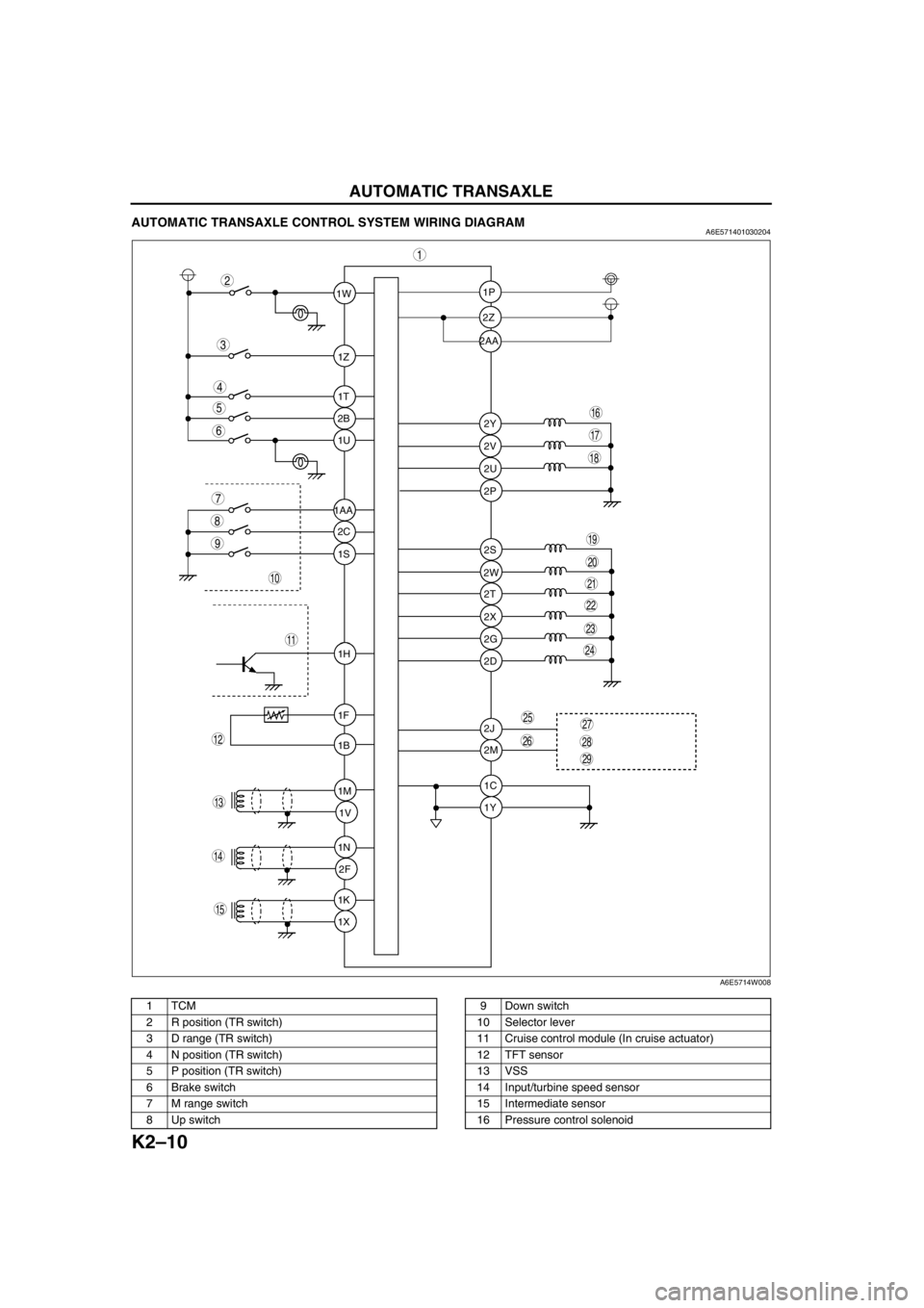
AUTOMATIC TRANSAXLE CONTROL SYSTEM WIRING DIAGRAMA6E571401030204
.
1W1P
2P
2S
2T
2X
2G
2D
2J
2M
1C
1Y 2W 2Z
2Y
2V
2U 1Z
1T
2B
1U
2C
1S
1H
1F
1B
1M
1V
1N
2F
1K
1X 1AA2AA
9
8
7
5
4
3
1
2
10
19
18
17
15
16
14
13
11
12
20
6
29
28
2725
26
24
23
21
22
A6E5714W008
1TCM
2 R position (TR switch)
3 D range (TR switch)
4 N position (TR switch)
5 P position (TR switch)
6 Brake switch
7 M range switch
8 Up switch9 Down switch
10 Selector lever
11 Cruise control module (In cruise actuator)
12 TFT sensor
13 VSS
14 Input/turbine speed sensor
15 Intermediate sensor
16 Pressure control solenoid
Page 426 of 909

AUTOMATIC TRANSAXLE
K2–11
K2
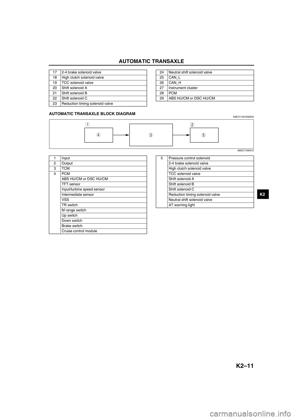
End Of SieAUTOMATIC TRANSAXLE BLOCK DIAGRAMA6E571401030205
.
17 2-4 brake solenoid valve
18 High clutch solenoid valve
19 TCC solenoid valve
20 Shift solenoid A
21 Shift solenoid B
22 Shift solenoid C
23 Reduction timing solenoid valve24 Neutral shift solenoid valve
25 CAN_L
26 CAN_H
27 Instrument cluster
28 PCM
29 ABS HU/CM or DSC HU/CM
543
12
A6E5714W012
1 Input
2Output
3TCM
4PCM
ABS HU/CM or DSC HU/CM
TFT sensor
Input/turbine speed sensor
Intermediate sensor
VSS
TR switch
M range switch
Up switch
Down switch
Brake switch
Cruise control module5 Pressure control solenoid
2-4 brake solenoid valve
High clutch solenoid valve
TCC solenoid valve
Shift solenoid A
Shift solenoid B
Shift solenoid C
Reduction timing solenoid valve
Neutral shift solenoid valve
AT warning light
Page 427 of 909

K2–12
AUTOMATIC TRANSAXLE
Electronic Control Item and Control
Component Description (Electronic Control)
Control item Contents
Shift control•Detects engine load condition and vehicle speed. Shifts to the best gear
position according to the programmed automatic shift diagram.
Line pressure control•Generates line pressure matching the engine load condition and driving
conditions. Optimizes line pressure for each shift. When the ATF
temperature is low, automatically optimizes line pressure for quick clutch
engagement.
Revers inhibition control•When the shift lever is shifted to R position while the vehicle is running
forward at approx. 30 km/h{19 mph} or more, the TCM turns the neutral
shift solenoid valve on and drains the low and reverse brake hydraulic
pressure. Due to this, the transaxle shifts to neutral.
Shift transient control•Adjusts transient hydraulic pressure according to engine load and
vehicle driving conditions when shifting using the pressure control
solenoid, 2-4 brake solenoid valve, the high clutch solenoid valve, and
each accumulator control valve.
•Temporarily lowers engine torque during shift (up and down) to improve
shift feel
•The lock timing for the reduction brake band is controlled by the control
of the reduction timing solenoid valve ON/OFF timing.
•The lock timing for the clutch brake is controlled by the control of shift
solenoid A, B, and C ON/OFF timing.
Feedback control•Corrects clutch engagement pressure and timing on drain side to
compensate for changes in engine performance and changes in
transaxle
TCC control•Controls TCC according to the programmed TCC points
N-D select control•When a driving range is selected from P/N, the fuel injection amount is
controlled to prevent fluctuation in engine speed.
Slope mode control•Changes the shift point to prevent frequent shifting up/down when
climbing hills
OBD system•Detects and/or memorizes failure of input/output part and transaxle
condition
Part name Function
Input system TR switch•Detects selector lever ranges/positions
Input/turbine speed sensor•Detects reverse clutch drum revolution speed
Intermediate sensor•Detects output gear revolution speed
Vehicle speedometer sensor•Detects parking gear revolution speed
TFT sensor•Detects the ATF temperature
Brake switch•Detects the brake pedal depressed
Cruise control module (in cruise actuator)•When the cruise control is in use, the signal detects when the
difference between the target speed and actual speed
exceeds specification
M range switch•Detects selector lever shifted M range
Up switch•Detects up shift in M range
Down switch•Detects down shift in M range
CAN signal Throttle position signal•Input throttle opening angle from PCM
Engine torque signal
(without torque down)•Input engine torque from PCM
Engine torque signal (with
torque down)•Input engine torque from PCM
Engine torque signal (loss
torque)•Input engine loss torque from PCM
Torque reduced signal•Detects signals indicating torque down availability
Engine coolant
temperature signal•Input engine coolant temperature from PCM
Engine speed signal•Input engine speed from PCM
Battery OFF signal•Detect negative battery cable disconnected
4 wheel speed signal•Input wheel speed from ABS HU/CM or DSC HU/CM