cruise control MAZDA 6 2002 Suplement User Guide
[x] Cancel search | Manufacturer: MAZDA, Model Year: 2002, Model line: 6, Model: MAZDA 6 2002Pages: 909, PDF Size: 17.16 MB
Page 172 of 909

F2–20
CONTROL SYSTEM
BLOCK DIAGRAMA6E404018881203
.
CRUISE
MAIN
CRUISE
9
8
7
5
4
3
10
6
1
2
14
13
11
12
19
18
17
15
16
20
29
28
27
25
26
24
23
21
22
30
37
35
36
33
31
32
34
39
38
40
49
48
47
45
46
44
43
41
42
50
51
52
53
A6E40402017
Page 173 of 909

CONTROL SYSTEM
F2–21
F2
End Of Sie
1PCM
2 Idle speed control
3Glow control
4 VSC
5 Boost pressure control
6 Fuel injection amount control
7 Fuel injection timing control
8 Multiple fuel injection control
9 Fuel pressure control
10 EGR control
11 Cruise control system
12 Electrical fan control
13 A/C cut-off control
14 Immobilizer system
15 Battery
16 Starter (starter signal)
17 Starter relay
18 Clutch switch
19 Neutral switch
20 Brake switch
21 Idle switch
22 A/C switch
23 Refrigerant pressure switch
24 Cruise control switch
25 Accelerator position sensor
26 MAF/IAT sensor
27 IAT sensor No.2
28 ECT sensor
29 Fuel temperature sensor
30 BARO sensor (integrated in PCM)
31 Boost sensor
32 Fuel pressure sensor
33 CMP sensor
34 CKP sensor
35 VSS
36 Calibration resistor
37 Immobilizer unit (integrated in PCM)
38 Suction control valve
39 IDM
40 VSC solenoid valve
41 VBC solenoid valve
42 EGR control solenoid valve
43 EGR solenoid valve (vacuum)
44 EGR solenoid valve (vent)
45 Intake shutter solenoid valve (half)
46 Intake shutter solenoid valve (full)
47 Glow indicator light
48 Cruise main indicator light
49 Cruise set indicator light
50 Glow plug relay
51 Cooling fan relay No.1
52 Cooling fan relay No.2
53 A/C relay
Page 174 of 909

F2–22
CONTROL SYSTEM
CONTROL DEVICE AND CONTROL RELATIONSHIP CHARTA6E404018881204
×: Applicable
End Of Sie
Item
Input device
Battery××
Starter (starter signal)××××××××× ×
Starter relay××××××××× ×
Clutch switch× × ××× ×× ×
Neutral switch× × ××× ×× ×
Brake switch×
Idle switch× × ××× × ×
A/C switch×××××
Refrigerant pressure switch×××××
Cruise control switch×
Accelerator position sensor××××××××
MAF/IAT sensor× ××××
IAT sensor No.2××
ECT sensor××× ××××× ××
Fuel temperature sensor×
BARO sensor (integrated in PCM)×××
Boost sensor××× ×
Fuel pressure sensor×× ××
CMP sensor×××××
CKP sensor× ××××××× ×
VSS××× ××× ××
Calibration resistor××
Immobilizer unit (integrated in PCM)×
Output device
Suction control valve××
IDM× ××× × ×
VSC solenoid valve×
VBC solenoid valve×
EGR control solenoid valve×
EGR solenoid valve (vacuum)×
EGR solenoid valve (vent)×
Intake shutter solenoid valve (half)×
Intake shutter solenoid valve (full)×
Glow indicator light×
Cruise main indicator light×
Cruise set indicator light×
Glow plug relay×
Cooling fan relay No.1×
Cooling fan relay No.2×
A/C relay×
Idle speed controlGlow controlVSCBoost pressure controlFuel injection amount controlFuel injection timing controlMultiple fuel injection controlFuel pressure controlEGR controlCruise control systemElectrical fan controlA/C cut-off controlImmobilizer system
Page 175 of 909

CONTROL SYSTEM
F2–23
F2
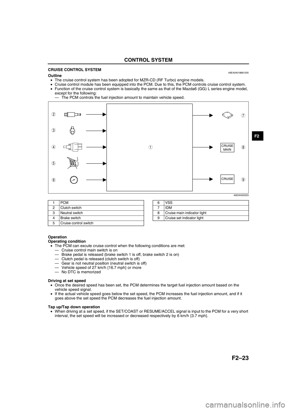
CRUISE CONTROL SYSTEMA6E404018881205Outline
•The cruise control system has been adopted for MZR-CD (RF Turbo) engine models.
•Cruise control module has been equipped into the PCM. Due to this, the PCM controls cruise control system.
•Function of the cruise control system is basically the same as that of the Mazda6 (GG) L series engine model,
except for the following:
—The PCM controls the fuel injection amount to maintain vehicle speed.
.
Operation
Operating condition
•The PCM can excute cruise control when the following conditions are met:
—Cruise control main switch is on
—Brake pedal is released (brake switch 1 is off, brake switch 2 is on)
—Clutch pedal is released (clutch switch is off)
—Gear is not neutral position (neutral switch is off)
—Vehicle speed of 27 km/h {16.7 mph} or more
—No DTC is memorized
Driving at set speed
•Once the desired speed has been set, the PCM determines the target fuel injection amount based on the
vehicle speed signal.
•If the actual vehicle speed goes below the set speed, the PCM increases the fuel injection amount, and if it
goes above the set speed the PCM decreases the fuel injection amount.
Tap up/Tap down operation
•When driving at a set speed, if the SET/COAST or RESUME/ACCEL signal is input to the PCM for a very short
interval, the set speed will be increased or decreased respectively by 6 km/h {3.7 mph}.
End Of Sie
CRUISE
MAIN
CRUISE
8
7
5
4
3
6
1
2
9
A6E40402025
1PCM
2 Clutch switch
3 Neutral switch
4 Brake switch
5 Cruise control switch6 VSS
7IDM
8 Cruise main indicator light
9 Cruise set indicator light
Page 176 of 909

F2–24
CONTROL SYSTEM, ON-BOARD DIAGNOSTIC
CONTROLLER AREA NETWORK (CAN)A6E404018881206Outline
•The PCM transmit/received the information other units using CAN to simplify the system.
Transmit Information
•Engine speed
•Vehicle speed
•Accelerator pedal position
•Fuel injection information
•Torque reduction inhibit
•Intake air temperature
•Engine coolant temperature
•Travelled distance
•Glow indicator light conditions
•Engine displacement
•Number of cylinders
•Air induction type
•Fuel type and delivery
•Country
•Transmission/axle type
•Tire circumference (front/rear)
•Cruise main indicator light conditions
•Cruise set indicator light conditions
Received Information
•Torque reduction request from DSC HU/CM
•Wheel speed from ABS HU/CM or DSC HU/CM
—Front left
—Front right
•Travelled distance from ABS HU/CM or DSC HU/CM
End Of Sie
OUTLINEA6E407018881201•The on-board diagnostic system is essentially carried over from that of the current MPV (LW) MZR-CD (RF
Turbo) engine models, except for the following. (See MPV Workshop Manual Supplement 1737-1*-02C.)
—DTCs, PID monitoring items, and simulation items have been changed.
—KOEO/KOER self-test items have been changed.
End Of Sie
DTCA6E407018881202
×: Applicable –: Not applicable
ON-BOARD DIAGNOSTIC
DTC Condition Detection condition MILMemory
function
P0016Crankshaft position-camshaft position
correlation malfunctionInput signals from CKP sensor and CMP sensor
are misaligned.××
P0088 Fuel pressure system too highFuel pressure is higher than preprogrammed
criteria.–×
P0091 Suction control valve circuit low inputInput voltage from suction control valve does not
change from off to on.××
P0092 Suction control valve circuit high inputInput voltage from suction control valve does not
change from on to off.××
P0093 Fuel system leak detectionFuel pressure after fuel injection is lower than
preprogrammed criteria.××
P0097 IAT sensor No.1 circuit low input Input voltage from IAT sensor No.1 is below 0.1 V.××
P0098 IAT sensor No.1 circuit high input Input voltage from IAT sensor No.1 is above 5.0 V.××
P0102 MAF sensor circuit low input Input voltage from MAF sensor is below 0.2 V.××
P0103 MAF sensor circuit high input Input voltage from MAF sensor is above 4.9 V.××
P0107 Boost sensor circuit low inputInput voltage from boost sensor is below 1.9 V
when engine speed is 2,400 rpm or above and
accelerator opening angle is 50% or above.××
P0108 Boost sensor circuit high input Input voltage from boost sensor is above 4.9 V.××
Page 177 of 909

ON-BOARD DIAGNOSTIC
F2–25
F2
P0112 IAT sensor No.2 circuit low input Input voltage from IAT sensor No.2 is below 0.1 V.××
P0113 IAT sensor No.2 circuit high input Input voltage from IAT sensor No.2 is above 5.0 V.××
P0117 ECT sensor circuit low input Input voltage from ECT sensor is below 0.1 V.××
P0118 ECT sensor circuit high input Input voltage from ECT sensor is above 5.0V.××
P0121Accelerator position sensor No.1 circuit
performance problemInput voltage from accelerator position sensor No.1
is above 1.3 V when accelerator pedal is
depressed.××
P0122Accelerator position sensor No.1 circuit
low inputInput voltage from accelerator position sensor No.1
is below 0.3 V.××
P0123Accelerator position sensor No.1 circuit
high inputInput voltage from accelerator position sensor No.1
is above 4.7 V.××
P0182 Fuel temperature sensor circuit low inputInput voltage from fuel temperature sensor is below
0.1 V.××
P0183 Fuel temperature sensor circuit high inputInput voltage from fuel temperature sensor is above
5.0 V.××
P0191Fuel pressure sensor circuit performance
problemPressure difference between actual fuel pressure
and target fuel pressure exceeds preprogrammed
criteria.××
P0192 Fuel pressure sensor circuit low inputInput voltage from fuel pressure sensor is below 0.4
V.××
P0193 Fuel pressure sensor circuit high inputInput voltage from fuel pressure sensor is above
4.8 V.××
P0200 Fuel injector circuit malfunction Injection confirmation signal is not input normally.××
P0221Accelerator position sensor No.2 circuit
performance problemVoltage difference between accelerator position
sensor No.1 and accelerator position sensor No.2
exceeds 0.9 V.××
P0222Accelerator position sensor No.2 circuit
low inputInput voltage from accelerator position sensor No.2
is below 0.3 V.××
P0223Accelerator position sensor No.2 circuit
high inputInput voltage from accelerator position sensor No.2
is above 4.7 V.××
P0300 Random misfire detectionInterval time of CKP sensor input signal exceeds
preprogrammed criteria.××
P0336 CKP sensor circuit performance problemInput signal from CKP sensor is not proper pulse
number.××
P0337 CKP sensor circuit low inputInput signal from CKP sensor is not input at 12
crankshaft revolutions.××
P0341 CMP sensor circuit performance problemInput signal from CMP sensor is not proper pulse
number.××
P0342 CMP sensor circuit low inputInput signal from CMP sensor is not input at 12
crankshaft revolutions.××
P0380 Glow plug relay circuit malfunctionInput voltage from glow plug relay is as following:
—1.0 V or below when glow plug relay is on.
—4.0 V or above when glow plug relay is off.××
P0504Brake switch signal correlation
malfunctionInput signal from brake switch 1 brake switch 2 is as
following:.
—Brake switch 1 is ON and brake switch 2 is ON.
—Brake switch 1 is OFF and brake switch 2 is
OFF.××
P0510 Idle switch circuit malfunctionInput voltage from idle switch is B+ when
accelerator position sensor No.1 voltage is below
0.7 V.××
P0512 Engine switch circuit malfunctionInput voltage from engine switch is B+ when engine
speed is 1,200 rpm or above.××
P0564 Cruise control signal malfunctionInput voltage from cruise control switch is as
following for 120 s:
—Below 0.1 V.
—1.4—1.9 V.
—3.7—3.9 V.
—4.5—4.6 V.××
P0602 PCM programming error No configuration data in PCM.××
P0606 PCM malfunction PCM does not read DTC from output devices.×× DTC Condition Detection condition MILMemory
function
Page 179 of 909

ON-BOARD DIAGNOSTIC
F2–27
F2
PID/DATA MONITOR AND RECORDA6E407018881204PID monitoring item table
End Of Sie
SIMULATION TESTA6E407018881205Simulation test item table
×: Applicable
Item Definition Condition/unit PCM terminal
ACCS A/C relay ON/OFF 73
ACSW A/C switch ON/OFF 84
APS1 Accelerator position sensor No.1 signal voltage V 10
APS2 Accelerator position sensor No.2 signal voltage V 88
BAROBarometric pressure kPa, inHg
-
Barometric pressure signal voltage V
BOO Brake switch ON/OFF 7
CPP Clutch switch ON/OFF 33
CPP/PNP Neutral switch Neutral/Drive 56
CRUISESW Cruise control switch ON/OFF 64
DTCCNT DTC count - -
ECTEngine coolant temperature°C, °F
87
Engine coolant temperature signal voltage V
FAN2 Cooling fan relay No.2 ON/OFF 76
FAN3 Cooling fan relay No.1 ON/OFF 102
IATIntake air temperature°C, °F
60
Intake air temperature signal voltage V
IMRC VSC solenoid valve ON/OFF 101
INGEAR In gear ON/OFF 33, 56
INJ_LRN_DIS Distance from the last injector learning Km, Mile -
MAFMass air flow amount g/s
9
Mass air flow signal voltage V
MAF_LRN_DIS Distance from the last MAF learning Km, Mile -
MAINRLY PCM control relay ON/OFF 69
MAPManifold absolute pressure kPa, inHg
36
Manifold absolute pressure signal voltage V
MIL Malfunction indicator lamp ON/OFF 71
NUMKEYS Number of keys stored in module - -
RPM Engine speed rpm 3, 29
VPWR Battery positive voltage V 27
VSS Vehicle speed km/h, mph 13, 39
Item Definition OperationTest condition
PCM
terminal
Key ON Idle
ACCS A/C relay ON or OFF××73
EGRA EGR solenoid valve (vent)Actuated by any duty value
(0—100%)××72
EGRV EGR solenoid valve (vacuum)Actuated by any duty value
(0—100%)××99
EGRV2 EGR control solenoid valve ON or OFF××77
FAN Cooling fan No.2 ON or OFF××76
FAN3 Cooling fan No.1 ON or OFF××102
GP_LMP Glow indicator light ON or OFF××97
GPC Glow plug relay ON or OFF××68
IASV Intake shutter solenoid valve (half) ON or OFF××74
IASV2 Intake shutter solenoid valve (full) ON or OFF××100
IMRC VSC solenoid valve ON or OFF××101
VBCV VBC solenoid valveActuated by any duty value
(0—100%)××67
Page 217 of 909

CONTROL SYSTEM
F2–65
F2
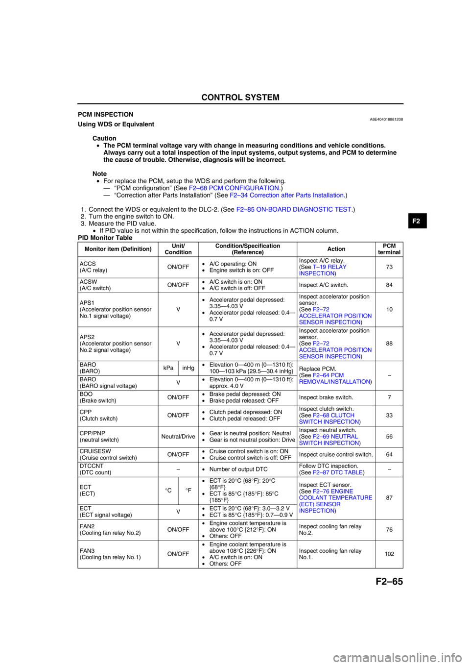
End Of SiePCM INSPECTIONA6E404018881208Using WDS or Equivalent
Caution
•The PCM terminal voltage vary with change in measuring conditions and vehicle conditions.
Always carry out a total inspection of the input systems, output systems, and PCM to determine
the cause of trouble. Otherwise, diagnosis will be incorrect.
Note
•For replace the PCM, setup the WDS and perform the following.
—“PCM configuration” (See F2–68 PCM CONFIGURATION.)
—“Correction after Parts Installation” (See F2–34 Correction after Parts Installation.)
1. Connect the WDS or equivalent to the DLC-2. (See F2–85 ON-BOARD DIAGNOSTIC TEST.)
2. Turn the engine switch to ON.
3. Measure the PID value.
•If PID value is not within the specification, follow the instructions in ACTION column.
PID Monitor Table
Monitor item (Definition)Unit/
ConditionCondition/Specification
(Reference)ActionPCM
terminal
ACCS
(A/C relay)ON/OFF•A/C operating: ON
•Engine switch is on: OFFInspect A/C relay.
(See T–19 RELAY
INSPECTION)73
ACSW
(A/C switch)ON/OFF•A/C switch is on: ON
•A/C switch is off: OFFInspect A/C switch. 84
APS1
(Accelerator position sensor
No.1 signal voltage)V•Accelerator pedal depressed:
3.35—4.03 V
•Accelerator pedal released: 0.4—
0.7 VInspect accelerator position
sensor.
(See F2–72
ACCELERATOR POSITION
SENSOR INSPECTION)10
APS2
(Accelerator position sensor
No.2 signal voltage)V•Accelerator pedal depressed:
3.35—4.03 V
•Accelerator pedal released: 0.4—
0.7 VInspect accelerator position
sensor.
(See F2–72
ACCELERATOR POSITION
SENSOR INSPECTION)88
BARO
(BARO)kPa inHg•Elevation 0—400 m {0—1310 ft}:
100—103 kPa {29.5—30.4 inHg}Replace PCM.
(See F2–64 PCM
REMOVAL/INSTALLATION)–
BARO
(BARO signal voltage)V•Elevation 0—400 m {0—1310 ft}:
approx. 4.0 V
BOO
(Brake switch)ON/OFF•Brake pedal depressed: ON
•Brake pedal released: OFFInspect brake switch. 7
CPP
(Clutch switch)ON/OFF•Clutch pedal depressed: ON
•Clutch pedal released: OFFInspect clutch switch.
(See F2–68 CLUTCH
SWITCH INSPECTION)33
CPP/PNP
(neutral switch)Neutral/Drive•Gear is neutral position: Neutral
•Gear is not neutral position: DriveInspect neutral switch.
(See F2–69 NEUTRAL
SWITCH INSPECTION)56
CRUISESW
(Cruise control switch)ON/OFF•Cruise control switch is on: ON
•Cruise control switch is off: OFFInspect cruise control switch. 64
DTCCNT
(DTC count)–•Number of output DTCFollow DTC inspection.
(See F2–87 DTC TABLE)–
ECT
(ECT)°C°F•ECT is 20°C {68°F}: 20°C
{68°F}
•ECT is 85°C {185°F}: 85°C
{185°F}Inspect ECT sensor.
(See F2–76 ENGINE
COOLANT TEMPERATURE
(ECT) SENSOR
INSPECTION)87
ECT
(ECT signal voltage)V•ECT is 20°C {68°F}: 3.0—3.2 V
•ECT is 85°C {185°F}: 0.7—0.9 V
FAN2
(Cooling fan relay No.2)ON/OFF•Engine coolant temperature is
above 100°C {212°F}: ON
•Others: OFFInspect cooling fan relay
No.2.76
FAN3
(Cooling fan relay No.1)ON/OFF•Engine coolant temperature is
above 108°C {226°F}: ON
•A/C switch is on: ON
•Others: OFFInspect cooling fan relay
No.1.102
Page 239 of 909

ON-BOARD DIAGNOSTIC
F2–87
F2
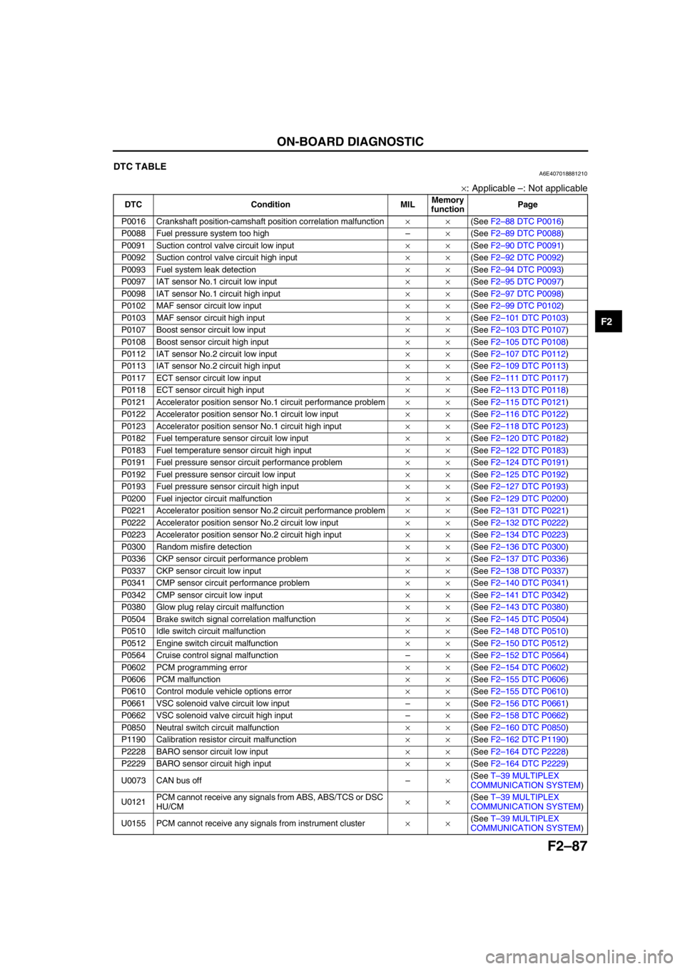
End Of SieDTC TABLEA6E407018881210
×: Applicable –: Not applicable
DTC Condition MILMemory
functionPage
P0016 Crankshaft position-camshaft position correlation malfunction××(See F2–88 DTC P0016)
P0088 Fuel pressure system too high–×(See F2–89 DTC P0088)
P0091 Suction control valve circuit low input××(See F2–90 DTC P0091)
P0092 Suction control valve circuit high input××(See F2–92 DTC P0092)
P0093 Fuel system leak detection××(See F2–94 DTC P0093)
P0097 IAT sensor No.1 circuit low input××(See F2–95 DTC P0097)
P0098 IAT sensor No.1 circuit high input××(See F2–97 DTC P0098)
P0102 MAF sensor circuit low input××(See F2–99 DTC P0102)
P0103 MAF sensor circuit high input××(See F2–101 DTC P0103)
P0107 Boost sensor circuit low input××(See F2–103 DTC P0107)
P0108 Boost sensor circuit high input××(See F2–105 DTC P0108)
P0112 IAT sensor No.2 circuit low input××(See F2–107 DTC P0112)
P0113 IAT sensor No.2 circuit high input××(See F2–109 DTC P0113)
P0117 ECT sensor circuit low input××(See F2–111 DTC P0117)
P0118 ECT sensor circuit high input××(See F2–113 DTC P0118)
P0121 Accelerator position sensor No.1 circuit performance problem××(See F2–115 DTC P0121)
P0122 Accelerator position sensor No.1 circuit low input××(See F2–116 DTC P0122)
P0123 Accelerator position sensor No.1 circuit high input××(See F2–118 DTC P0123)
P0182 Fuel temperature sensor circuit low input××(See F2–120 DTC P0182)
P0183 Fuel temperature sensor circuit high input××(See F2–122 DTC P0183)
P0191 Fuel pressure sensor circuit performance problem××(See F2–124 DTC P0191)
P0192 Fuel pressure sensor circuit low input××(See F2–125 DTC P0192)
P0193 Fuel pressure sensor circuit high input××(See F2–127 DTC P0193)
P0200 Fuel injector circuit malfunction××(See F2–129 DTC P0200)
P0221 Accelerator position sensor No.2 circuit performance problem××(See F2–131 DTC P0221)
P0222 Accelerator position sensor No.2 circuit low input××(See F2–132 DTC P0222)
P0223 Accelerator position sensor No.2 circuit high input××(See F2–134 DTC P0223)
P0300 Random misfire detection××(See F2–136 DTC P0300)
P0336 CKP sensor circuit performance problem××(See F2–137 DTC P0336)
P0337 CKP sensor circuit low input××(See F2–138 DTC P0337)
P0341 CMP sensor circuit performance problem××(See F2–140 DTC P0341)
P0342 CMP sensor circuit low input××(See F2–141 DTC P0342)
P0380 Glow plug relay circuit malfunction××(See F2–143 DTC P0380)
P0504 Brake switch signal correlation malfunction××(See F2–145 DTC P0504)
P0510 Idle switch circuit malfunction××(See F2–148 DTC P0510)
P0512 Engine switch circuit malfunction××(See F2–150 DTC P0512)
P0564 Cruise control signal malfunction–×(See F2–152 DTC P0564)
P0602 PCM programming error××(See F2–154 DTC P0602)
P0606 PCM malfunction××(See F2–155 DTC P0606)
P0610 Control module vehicle options error××(See F2–155 DTC P0610)
P0661 VSC solenoid valve circuit low input–×(See F2–156 DTC P0661)
P0662 VSC solenoid valve circuit high input–×(See F2–158 DTC P0662)
P0850 Neutral switch circuit malfunction××(See F2–160 DTC P0850)
P1190 Calibration resistor circuit malfunction××(See F2–162 DTC P1190)
P2228 BARO sensor circuit low input××(See F2–164 DTC P2228)
P2229 BARO sensor circuit high input××(See F2–164 DTC P2229)
U0073 CAN bus off–×(See T–39 MULTIPLEX
COMMUNICATION SYSTEM)
U0121PCM cannot receive any signals from ABS, ABS/TCS or DSC
HU/CM××(See T–39 MULTIPLEX
COMMUNICATION SYSTEM)
U0155 PCM cannot receive any signals from instrument cluster××(See T–39 MULTIPLEX
COMMUNICATION SYSTEM)
Page 304 of 909

F2–152
ON-BOARD DIAGNOSTIC
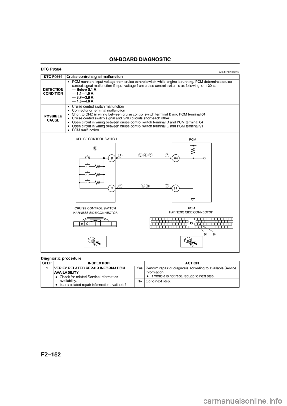
DTC P0564A6E407001082237
Diagnostic procedure
DTC P0564 Cruise control signal malfunction
DETECTION
CONDITION•PCM monitors input voltage from cruise control switch while engine is running. PCM determines cruise
control signal malfunction if input voltage from cruise control switch is as following for 120 s:
—Below 0.1 V.
—1.4—1.9 V.
—3.7—3.9 V.
—4.5—4.6 V.
POSSIBLE
CAUSE•Cruise control switch malfunction
•Connector or terminal malfunction
•Short to GND in wiring between cruise control switch terminal B and PCM terminal 64
•Cruise control switch signal and GND circuits short each other
•Open circuit in wiring between cruise control switch terminal B and PCM terminal 64
•Open circuit in wiring between cruise control switch terminal C and PCM terminal 91
•PCM malfunction
STEP INSPECTION ACTION
1VERIFY RELATED REPAIR INFORMATION
AVAILABILITY
•Check for related Service Information
availability.
•Is any related repair information available?Yes Perform repair or diagnosis according to available Service
Information.
•If vehicle is not repaired, go to next step.
No Go to next step.
CRUISE CONTROL SWITCH
PCM
B
C64
91
CRUISE CONTROL SWITCH
HARNESS SIDE CONNECTORPCM
HARNESS SIDE CONNECTOR
BC
64 91
2
2
543
4
7
6
78