cruise control MAZDA 6 2002 Suplement Owner's Guide
[x] Cancel search | Manufacturer: MAZDA, Model Year: 2002, Model line: 6, Model: MAZDA 6 2002Pages: 909, PDF Size: 17.16 MB
Page 428 of 909
AUTOMATIC TRANSAXLE
K2–13
K2
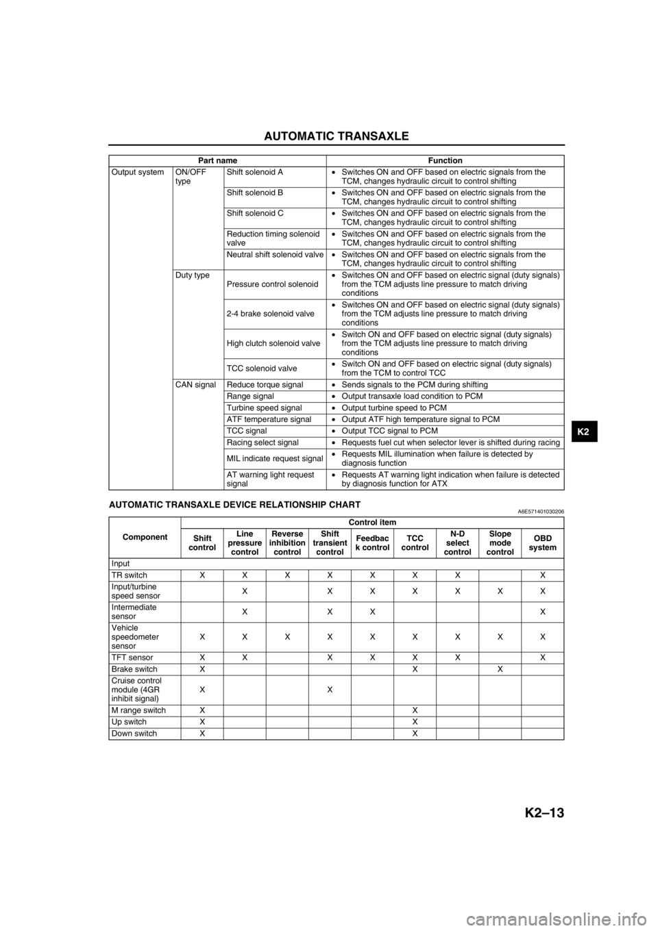
End Of SieAUTOMATIC TRANSAXLE DEVICE RELATIONSHIP CHARTA6E571401030206
Output system ON/OFF
typeShift solenoid A•Switches ON and OFF based on electric signals from the
TCM, changes hydraulic circuit to control shifting
Shift solenoid B•Switches ON and OFF based on electric signals from the
TCM, changes hydraulic circuit to control shifting
Shift solenoid C•Switches ON and OFF based on electric signals from the
TCM, changes hydraulic circuit to control shifting
Reduction timing solenoid
valve•Switches ON and OFF based on electric signals from the
TCM, changes hydraulic circuit to control shifting
Neutral shift solenoid valve•Switches ON and OFF based on electric signals from the
TCM, changes hydraulic circuit to control shifting
Duty type
Pressure control solenoid•Switches ON and OFF based on electric signal (duty signals)
from the TCM adjusts line pressure to match driving
conditions
2-4 brake solenoid valve•Switches ON and OFF based on electric signal (duty signals)
from the TCM adjusts line pressure to match driving
conditions
High clutch solenoid valve•Switch ON and OFF based on electric signal (duty signals)
from the TCM adjusts line pressure to match driving
conditions
TCC solenoid valve•Switch ON and OFF based on electric signal (duty signals)
from the TCM to control TCC
CAN signal Reduce torque signal•Sends signals to the PCM during shifting
Range signal•Output transaxle load condition to PCM
Turbine speed signal•Output turbine speed to PCM
ATF temperature signal•Output ATF high temperature signal to PCM
TCC signal•Output TCC signal to PCM
Racing select signal•Requests fuel cut when selector lever is shifted during racing
MIL indicate request signal•Requests MIL illumination when failure is detected by
diagnosis function
AT warning light request
signal•Requests AT warning light indication when failure is detected
by diagnosis function for ATX Part name Function
ComponentControl item
Shift
controlLine
pressure
controlReverse
inhibition
controlShift
transient
controlFeedbac
k controlTCC
controlN-D
select
controlSlope
mode
controlOBD
system
Input
TR switch XXXXXXX X
Input/turbine
speed sensorX XXXXXX
Intermediate
sensorXXX X
Vehicle
speedometer
sensorXXXXXXXXX
TFT sensor XX XXXX X
Brake switch X X X
Cruise control
module (4GR
inhibit signal)XX
M range switch X X
Up switch X X
Down switch X X
Page 470 of 909
AUTOMATIC TRANSAXLE
K2–55
K2
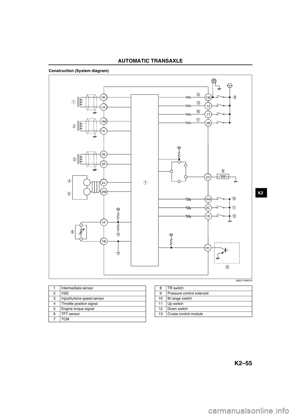
Construction (System diagram)
.
1T 1Z 1W
1AA
2C 2Y
1S
1H2B 1K
1X
1M
1V
1N
2F
2J
2M
1F
1B
9
8
7
5
4
3
1
2
10
17
15
16
14
13
11
12
6
A6E5714W019
1 Intermediate sensor
2 VSS
3 Input/turbine speed sensor
4 Throttle position signal
5 Engine torque signal
6 TFT sensor
7TCM8TR switch
9 Pressure control solenoid
10 M range switch
11 Up switch
12 Down switch
13 Cruise control module
Page 506 of 909
AUTOMATIC TRANSAXLE
K2–91
K2
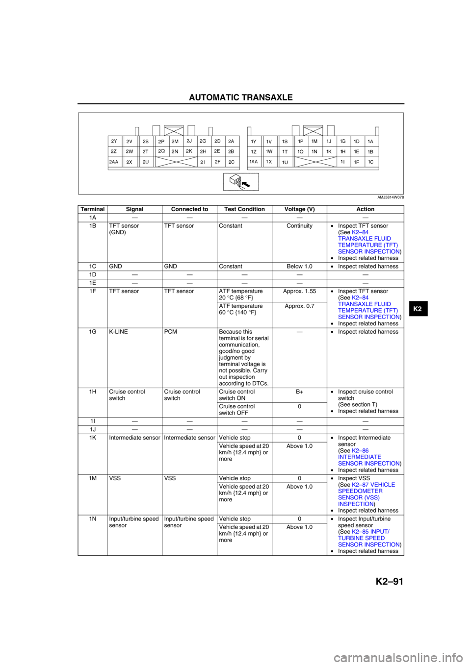
Terminal Signal Connected to Test Condition Voltage (V) Action
1A———— —
1B TFT sensor
(GND)TFT sensor Constant Continuity•Inspect TFT sensor
(See K2–84
TRANSAXLE FLUID
TEMPERATURE (TFT)
SENSOR INSPECTION)
•Inspect related harness
1C GND GND Constant Below 1.0•Inspect related harness
1D———— —
1E———— —
1F TFT sensor TFT sensor ATF temperature
20 °C {68 °F}Approx. 1.55•Inspect TFT sensor
(See K2–84
TRANSAXLE FLUID
TEMPERATURE (TFT)
SENSOR INSPECTION)
•Inspect related harness ATF temperature
60 °C {140 °F}Approx. 0.7
1G K-LINE PCM Because this
terminal is for serial
communication,
good/no good
judgment by
terminal voltage is
not possible. Carry
out inspection
according to DTCs.—•Inspect related harness
1H Cruise control
switchCruise control
switchCruise control
switch ONB+•Inspect cruise control
switch
(See section T)
•Inspect related harness Cruise control
switch OFF0
1I———— —
1J———— —
1K Intermediate sensor Intermediate sensor Vehicle stop 0•Inspect Intermediate
sensor
(See K2–86
INTERMEDIATE
SENSOR INSPECTION)
•Inspect related harness Vehicle speed at 20
km/h {12.4 mph} or
moreAbove 1.0
1M VSS VSS Vehicle stop 0•Inspect VSS
(See K2–87 VEHICLE
SPEEDOMETER
SENSOR (VSS)
INSPECTION)
•Inspect related harness Vehicle speed at 20
km/h {12.4 mph} or
moreAbove 1.0
1N Input/turbine speed
sensorInput/turbine speed
sensorVehicle stop 0•Inspect Input/turbine
speed sensor
(See K2–85 INPUT/
TURBINE SPEED
SENSOR INSPECTION)
•Inspect related harness Vehicle speed at 20
km/h {12.4 mph} or
moreAbove 1.0
AMJ5814W078
Page 605 of 909
K2–190
TROUBLESHOOTING
Diagnostic procedure
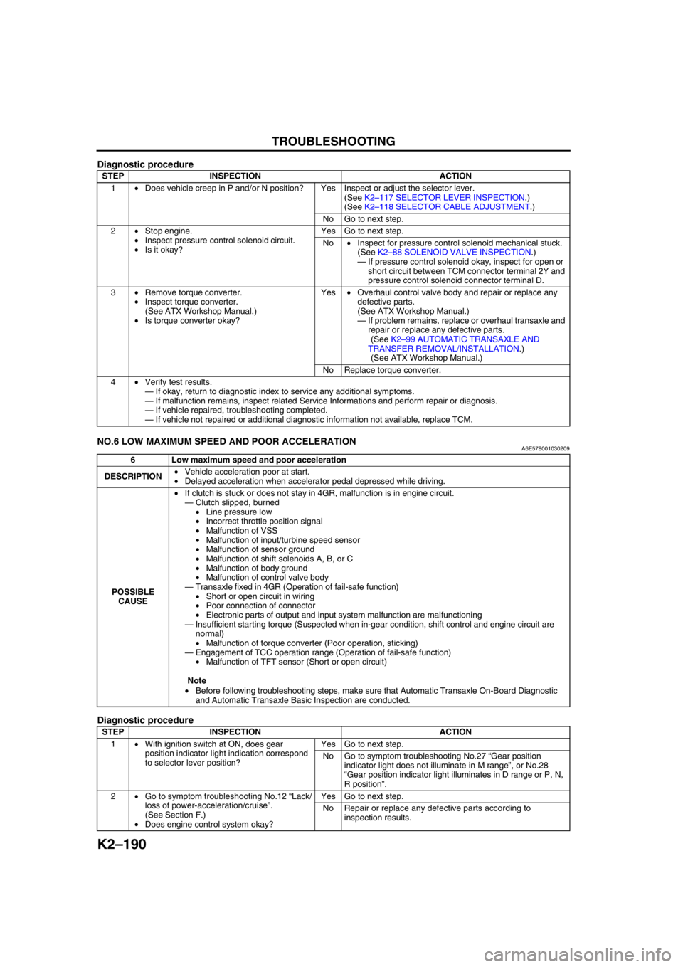
End Of SieNO.6 LOW MAXIMUM SPEED AND POOR ACCELERATIONA6E578001030209
Diagnostic procedure
STEP INSPECTION ACTION
1•Does vehicle creep in P and/or N position? Yes Inspect or adjust the selector lever.
(See K2–117 SELECTOR LEVER INSPECTION.)
(See K2–118 SELECTOR CABLE ADJUSTMENT.)
No Go to next step.
2•Stop engine.
•Inspect pressure control solenoid circuit.
•Is it okay?Yes Go to next step.
No•Inspect for pressure control solenoid mechanical stuck.
(See K2–88 SOLENOID VALVE INSPECTION.)
—If pressure control solenoid okay, inspect for open or
short circuit between TCM connector terminal 2Y and
pressure control solenoid connector terminal D.
3•Remove torque converter.
•Inspect torque converter.
(See ATX Workshop Manual.)
•Is torque converter okay?Yes•Overhaul control valve body and repair or replace any
defective parts.
(See ATX Workshop Manual.)
—If problem remains, replace or overhaul transaxle and
repair or replace any defective parts.
(See K2–99 AUTOMATIC TRANSAXLE AND
TRANSFER REMOVAL/INSTALLATION.)
(See ATX Workshop Manual.)
No Replace torque converter.
4•Verify test results.
—If okay, return to diagnostic index to service any additional symptoms.
—If malfunction remains, inspect related Service Informations and perform repair or diagnosis.
—If vehicle repaired, troubleshooting completed.
—If vehicle not repaired or additional diagnostic information not available, replace TCM.
6 Low maximum speed and poor acceleration
DESCRIPTION•Vehicle acceleration poor at start.
•Delayed acceleration when accelerator pedal depressed while driving.
POSSIBLE
CAUSE•If clutch is stuck or does not stay in 4GR, malfunction is in engine circuit.
—Clutch slipped, burned
•Line pressure low
•Incorrect throttle position signal
•Malfunction of VSS
•Malfunction of input/turbine speed sensor
•Malfunction of sensor ground
•Malfunction of shift solenoids A, B, or C
•Malfunction of body ground
•Malfunction of control valve body
—Transaxle fixed in 4GR (Operation of fail-safe function)
•Short or open circuit in wiring
•Poor connection of connector
•Electronic parts of output and input system malfunction are malfunctioning
—Insufficient starting torque (Suspected when in-gear condition, shift control and engine circuit are
normal)
•Malfunction of torque converter (Poor operation, sticking)
—Engagement of TCC operation range (Operation of fail-safe function)
•Malfunction of TFT sensor (Short or open circuit)
Note
•Before following troubleshooting steps, make sure that Automatic Transaxle On-Board Diagnostic
and Automatic Transaxle Basic Inspection are conducted.
STEP INSPECTION ACTION
1•With ignition switch at ON, does gear
position indicator light indication correspond
to selector lever position?Yes Go to next step.
No Go to symptom troubleshooting No.27 “Gear position
indicator light does not illuminate in M range”, or No.28
“Gear position indicator light illuminates in D range or P, N,
R position”.
2•Go to symptom troubleshooting No.12 “Lack/
loss of power-acceleration/cruise”.
(See Section F.)
•Does engine control system okay?Yes Go to next step.
No Repair or replace any defective parts according to
inspection results.
Page 738 of 909

ABS/TCS
P–5
P
System Diagram
.
End Of Sie
9
9
8
7
5
43
12
6
18
17
15
16
14
13
11
12
RF
FL
RR
RL
PCMG
E
FI Z
U
D
A
B
C
Y
AC
X
V O
R ADAB AA
ABS/TCS HU/CM
pP
9
10
19
920
A6E6921W201
1 IG switch
2SUS 15 A fuse
3 ABS 60 A fuse
4 Meter
5 ABS warning light
6 Brake system warning light
7 TCS OFF light
8 TCS indicator light
9CAN driver
10 Brake light11 Cruise actuator
12 TCS OFF switch
13 DLC-2
14 CAN-H
15 CAN-L
16 ABS Wheel-speed sensor
17 Battery
18 Brake switch
19 Audio unit, Wiper and washer switch, Car-navigation
unit, Auto leveling control unit
20 TCM, 4WD CM
Page 740 of 909

DYNAMIC STABILITY CONTROL
P–7
P
Wiring Diagram
.
9
RF
FL
RR
RL
PCM
G
E
M
I
F
K
H
Q
NJ
P
S
T
V
O
Y
X
W
U
R
L
Z
AC
D
B
AG
AF
AE
AC
AA
AB
C
F
D
A
B
EDSC HU/CM
A
B
C
D
F
1
3
2
8
7
5
4
6
9
9
9
10
11
13
12
15
14
18
17
16
1920
2122
24
23
A6E6921W203
1 IG switch
2SUS 15A fuse
3 ABS 60 A fuse
4 Meter
5 ABS warning light
6 Brake system warning light
7 DSC OFF light
8 DSC indicator light
9CAN driver
10 Battery
11 Cruise actuator
12 DSC OFF switch13 DLC-2
14 CAN-H
15 CAN-L
16 Wheel-speed sensor
17 Combine sensor
18 Steering angle sensor
19 Brake switch
20 Brake light
21 Back-up light switch (MTX only)
22 Back-up light (MTX only)
23 Audio unit, Wiper and washer switch, Car-navigation
unit, Auto leveling control unit
24 TCM, 4WD CM
Page 752 of 909

DYNAMIC STABILITY CONTROL
P–19
P
*: Used for vehicle manufacturing, not used for DSC.
Inspection Using An Oscilloscope (Reference)
Steering angle (steering angle signal 1 and 2)
•DSC HU/CM terminal:
Steering angle signal 2: W (+) — R (-)
Steering angle signal 1: X (+) — R (-)
•Oscilloscope setting:
1 V/DIV (Y), 25 ms/DIV (X), DC range
•Vehicle condition: Rotating steering wheel at one
revolution per second
Note
•As steering wheel rotation speed increases,
period of wave shortens.
•As for shape of steering angle signals 1 and
2, the phase is different.
Wheel speed
•DSC HU/CM terminal:
RF: M (+) — I (-)
RR: K (+) — H (-)
LF: F (+) — J (-)
LR: Q (+) — N (-)
•Oscilloscope setting:
1 V/DIV (Y), 2 ms/DIV (X), AC range
•Vehicle condition: Driving 30 km/h (18.6 mph)
Note
•As vehicle speed increases, period of wave
shortens.
•If there is malfunctioning in the sensor rotor,
wave profile warps.
ACAuto cruise set
signal outputAuto cruise unitWhen auto cruise is ON Below 1.0
•Inspect related harness
•Inspect DSC HU/CM
When auto cruise is OFF B+
AD—— — — —
AEVehicle speed
output•Audio unit
•Wiper and
washer
switch
•Car-navigatio
n unit
•Auto
leveling
control unit
•Cruise
actuatorVehicle is stopped 0
•Inspect related harness
•Inspect front wheel-speed
sensor •Inspect using the wave profile.
(See P–19 Inspection Using An
Oscilloscope (Reference))
AF CAN-L——No need to
check—
AG CAN-H——No need to
check—
AH—— — — — Terminal Signal Connected to Test condition Voltage (V) Action
0 V
A6E6921W014
0 V
A6E6921W013
Page 812 of 909
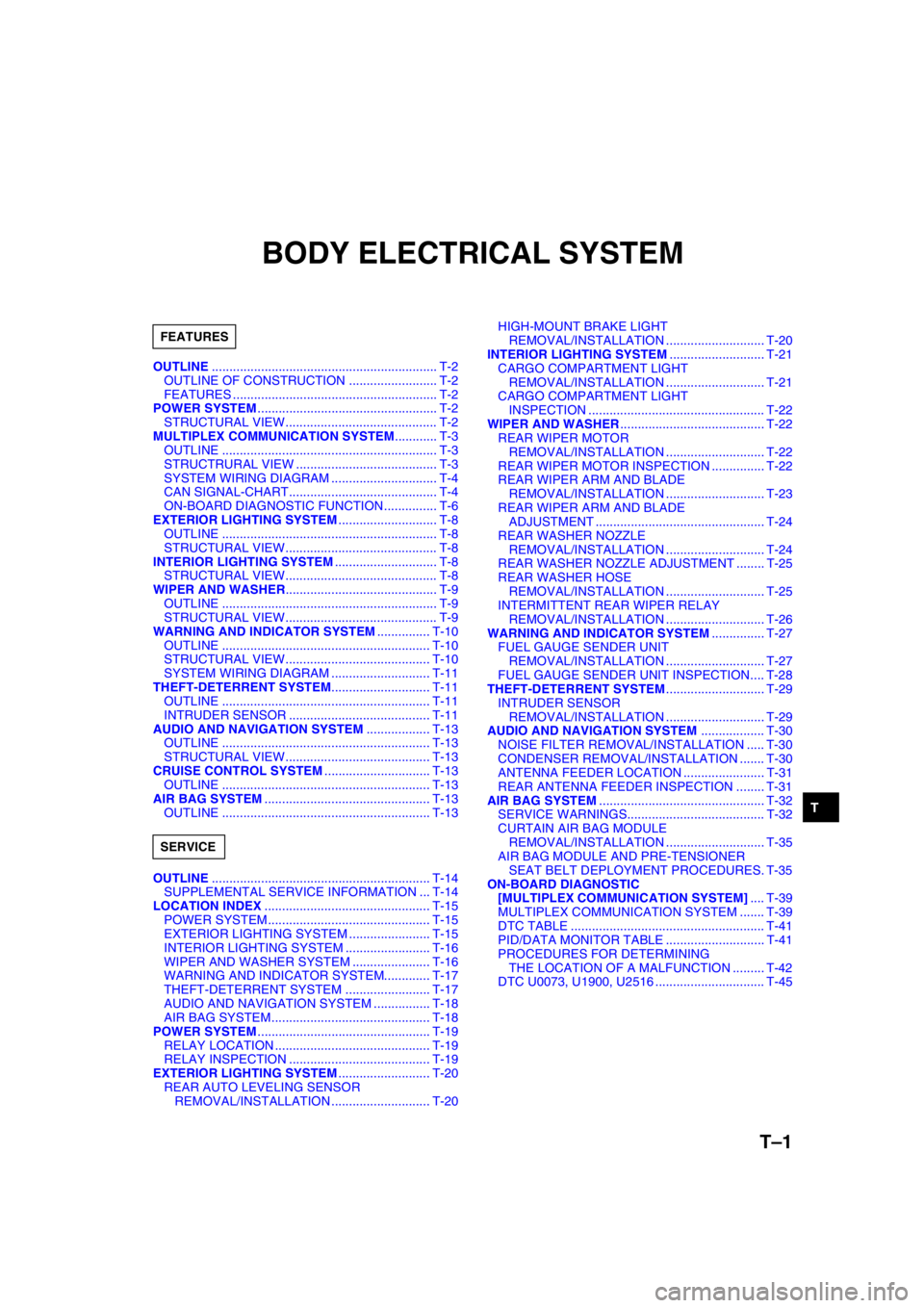
T–1
T
TBODY ELECTRICAL SYSTEM
OUTLINE................................................................ T-2
OUTLINE OF CONSTRUCTION ......................... T-2
FEATURES .......................................................... T-2
POWER SYSTEM................................................... T-2
STRUCTURAL VIEW........................................... T-2
MULTIPLEX COMMUNICATION SYSTEM............ T-3
OUTLINE ............................................................. T-3
STRUCTRURAL VIEW ........................................ T-3
SYSTEM WIRING DIAGRAM .............................. T-4
CAN SIGNAL-CHART.......................................... T-4
ON-BOARD DIAGNOSTIC FUNCTION............... T-6
EXTERIOR LIGHTING SYSTEM............................ T-8
OUTLINE ............................................................. T-8
STRUCTURAL VIEW........................................... T-8
INTERIOR LIGHTING SYSTEM............................. T-8
STRUCTURAL VIEW........................................... T-8
WIPER AND WASHER........................................... T-9
OUTLINE ............................................................. T-9
STRUCTURAL VIEW........................................... T-9
WARNING AND INDICATOR SYSTEM............... T-10
OUTLINE ........................................................... T-10
STRUCTURAL VIEW......................................... T-10
SYSTEM WIRING DIAGRAM ............................ T-11
THEFT-DETERRENT SYSTEM............................ T-11
OUTLINE ........................................................... T-11
INTRUDER SENSOR ........................................ T-11
AUDIO AND NAVIGATION SYSTEM.................. T-13
OUTLINE ........................................................... T-13
STRUCTURAL VIEW......................................... T-13
CRUISE CONTROL SYSTEM.............................. T-13
OUTLINE ........................................................... T-13
AIR BAG SYSTEM............................................... T-13
OUTLINE ........................................................... T-13
OUTLINE.............................................................. T-14
SUPPLEMENTAL SERVICE INFORMATION ... T-14
LOCATION INDEX............................................... T-15
POWER SYSTEM.............................................. T-15
EXTERIOR LIGHTING SYSTEM ....................... T-15
INTERIOR LIGHTING SYSTEM ........................ T-16
WIPER AND WASHER SYSTEM ...................... T-16
WARNING AND INDICATOR SYSTEM............. T-17
THEFT-DETERRENT SYSTEM ........................ T-17
AUDIO AND NAVIGATION SYSTEM ................ T-18
AIR BAG SYSTEM............................................. T-18
POWER SYSTEM................................................. T-19
RELAY LOCATION ............................................ T-19
RELAY INSPECTION ........................................ T-19
EXTERIOR LIGHTING SYSTEM.......................... T-20
REAR AUTO LEVELING SENSOR
REMOVAL/INSTALLATION ............................ T-20HIGH-MOUNT BRAKE LIGHT
REMOVAL/INSTALLATION ............................ T-20
INTERIOR LIGHTING SYSTEM........................... T-21
CARGO COMPARTMENT LIGHT
REMOVAL/INSTALLATION ............................ T-21
CARGO COMPARTMENT LIGHT
INSPECTION .................................................. T-22
WIPER AND WASHER......................................... T-22
REAR WIPER MOTOR
REMOVAL/INSTALLATION ............................ T-22
REAR WIPER MOTOR INSPECTION ............... T-22
REAR WIPER ARM AND BLADE
REMOVAL/INSTALLATION ............................ T-23
REAR WIPER ARM AND BLADE
ADJUSTMENT ................................................ T-24
REAR WASHER NOZZLE
REMOVAL/INSTALLATION ............................ T-24
REAR WASHER NOZZLE ADJUSTMENT ........ T-25
REAR WASHER HOSE
REMOVAL/INSTALLATION ............................ T-25
INTERMITTENT REAR WIPER RELAY
REMOVAL/INSTALLATION ............................ T-26
WARNING AND INDICATOR SYSTEM............... T-27
FUEL GAUGE SENDER UNIT
REMOVAL/INSTALLATION ............................ T-27
FUEL GAUGE SENDER UNIT INSPECTION.... T-28
THEFT-DETERRENT SYSTEM............................ T-29
INTRUDER SENSOR
REMOVAL/INSTALLATION ............................ T-29
AUDIO AND NAVIGATION SYSTEM.................. T-30
NOISE FILTER REMOVAL/INSTALLATION ..... T-30
CONDENSER REMOVAL/INSTALLATION ....... T-30
ANTENNA FEEDER LOCATION ....................... T-31
REAR ANTENNA FEEDER INSPECTION ........ T-31
AIR BAG SYSTEM............................................... T-32
SERVICE WARNINGS....................................... T-32
CURTAIN AIR BAG MODULE
REMOVAL/INSTALLATION ............................ T-35
AIR BAG MODULE AND PRE-TENSIONER
SEAT BELT DEPLOYMENT PROCEDURES. T-35
ON-BOARD DIAGNOSTIC
[MULTIPLEX COMMUNICATION SYSTEM].... T-39
MULTIPLEX COMMUNICATION SYSTEM ....... T-39
DTC TABLE ....................................................... T-41
PID/DATA MONITOR TABLE ............................ T-41
PROCEDURES FOR DETERMINING
THE LOCATION OF A MALFUNCTION ......... T-42
DTC U0073, U1900, U2516 ............................... T-45 FEATURES
SERVICE
Page 816 of 909

MULTIPLEX COMMUNICATION SYSTEM
T–5
T
End Of Sie
Cruise main indicator light
conditions (MZR-CD (RF
Turbo))OUT–––IN
Cruise set indicator light
conditions (MZR-CD (RF
Turbo))OUT–––IN
Desired gear/
selector lever
positionFN4A-EL OUT–IN–IN
JA5AX-EL IN OUT IN IN IN
ECT OUT IN–IN
Engine control condition OUT–IN––
Engine displacement OUT–IN––
Engine loss torque (except
MZR-CD (RF Turbo))OUT IN–––
Engine speed OUT IN IN IN IN
Engine torque (except
MZR-CD (RF Turbo))OUT IN–––
Fuel injection information OUT–IN––
Fuel type and delivery OUT–IN––
Gear position IN OUT IN IN IN
Generator warning light
conditions (except MZR-
CD (RF Turbo))OUT–––IN
Glow indicator light
condition (MZR-CD (RF
Turbo))OUT–––IN
HOLD indicator light
conditions (FN4A-EL)OUT–––IN
Idle speed up request IN OUT–––
MIL condition (except
MZR-CD (RF Turbo))OUT–––IN
MIL indicate request IN OUT–––
Number of cylinders OUT–IN––
Racing select
determinationIN OUT–––
TCC condition IN OUT–––
Tire circumference (front/
rear)OUT–IN––
Torque reduction inhibit OUT IN IN––
TP OUTINININ–
Transmission/axle type OUT–IN––
Travelled distanceIN–OUT––
IN OUT––IN
OUT–––IN
Torque
reduction
requestJA5AX-EL IN OUT–––
except
JA5AX-ELIN–OUT––
Turbine speed IN OUT–––
Upper torque limit IN OUT–––
Vehicle speedOUT–––IN
IN OUT–––
Wheel speed (front left/
front right/rear left/rear
right)IN IN OUT IN–
OUT–––IN
4WD system operating
condition (warning light
information)–––OUT IN SignalMultiplex module
PCM TCMABS (ABS/TCS)
HU/CM or
DSC HU/CM4WD control
moduleInstrument
cluster
Page 824 of 909

AUDIO AND NAVIGATION SYSTEM, CRUISE CONTROL SYSTEM, AIR BAG SYSTEM
T–13
T
OUTLINEA6E812401052201•Due to the adoption of the WGN, the following have been changed:
—Installation positions of the condenser and the noise filter
—Antenna feeder routing
End Of Sie
STRUCTURAL VIEWA6E812401052202
.
End Of Sie
OUTLINEA6E812801052201•The PCM controls the cruise control system. Refer to Section F for details regarding PCM control. (SeeF2–23
CRUISE CONTROL SYSTEM)
End Of Sie
OUTLINEA6E813001046201•Due to the adoption of the WGN, the shape of the curtain air bag module has been modified.
End Of Sie
AUDIO AND NAVIGATION SYSTEM
1
2
3
A6E8124T101
1 Rear antenna feeder
2 Condenser3 Noise filter
CRUISE CONTROL SYSTEM
AIR BAG SYSTEM