key MAZDA 6 2002 Suplement Service Manual
[x] Cancel search | Manufacturer: MAZDA, Model Year: 2002, Model line: 6, Model: MAZDA 6 2002Pages: 909, PDF Size: 17.16 MB
Page 583 of 909

K2–168
ON-BOARD DIAGNOSTIC
End Of Sie
11INSPECT TCM CIRCUIT FOR SHORT TO
GROUND
•Turn ignition key to OFF.
•Check continuity between TCM terminal 2D
(harness-side) and body ground.
•Is there any continuity?Yes Repair or replace harness, then go to next step.
No Go to next step.
12VERIFY TROUBLESHOOTING OF DTC P0773
COMPLETED
•Make sure to reconnect all disconnected
connectors.
•Clear DTC from memory using WDS or
equivalent.
•Drive vehicle in D range and make sure that
gears shift smoothly from 1GR to 5GR.
•Is same DTC present?Yes Replace TCM, then go to next step.
(See K2–96 TCM REMOVAL/INSTALLATION.)
No Go to next step.
13VERIFY AFTER REPAIR PROCEDURE
•Perform “After Repair Procedure”.
(See K2–124 AFTER REPAIR PROCEDURE.)
•Is there any DTC present?Yes Go to applicable DTC inspection.
No Troubleshooting completed. STEP INSPECTION ACTION
Page 585 of 909
K2–170
ON-BOARD DIAGNOSTIC
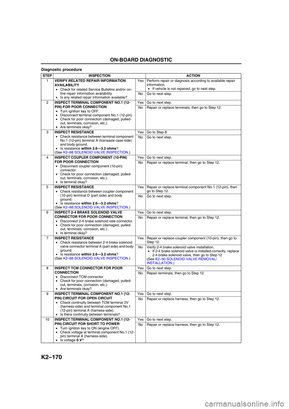
Diagnostic procedure
STEP INSPECTION ACTION
1VERIFY RELATED REPAIR INFORMATION
AVAILABILITY
•Check for related Service Bulletins and/or on-
line repair information availability.
•Is any related repair information available?Yes Perform repair or diagnosis according to available repair
information.
•If vehicle is not repaired, go to next step.
No Go to next step.
2INSPECT TERMINAL COMPONENT NO.1 (12-
PIN) FOR POOR CONNECTION
•Turn ignition key to OFF.
•Disconnect terminal component No.1 (12-pin).
•Check for poor connection (damaged, pulled-
out, terminals, corrosion, etc.).
•Are terminals okay?Yes Go to next step.
No Repair or replace terminals, then go to Step 12.
3INSPECT RESISTANCE
•Check resistance between terminal component
No.1 (12-pin) terminal A (transaxle case side)
and body ground.
•Is resistance within 2.6—3.2 ohms?
(See K2–88 SOLENOID VALVE INSPECTION.)Yes Go to Step 8.
No Go to next step.
4INSPECT COUPLER COMPONENT (10-PIN)
FOR POOR CONNECTION
•Disconnect coupler component (10-pin)
connector.
•Check for poor connection (damaged, pulled-
out, terminals, corrosion, etc.).
•Is terminal okay?Yes Go to next step.
No Repair or replace terminal, then go to Step 12.
5INSPECT RESISTANCE
•Check resistance between coupler component
(10-pin) terminal D (part side) and body
ground.
•Is resistance within 2.6—3.2 ohms?
(See K2–88 SOLENOID VALVE INSPECTION.)Yes Repair or replace terminal component No.1 (12-pin), then
go to Step 12.
No Go to next step.
6INSPECT 2-4 BRAKE SOLENOID VALVE
CONNECTOR FOR POOR CONNECTION
•Disconnect 2-4 brake solenoid vale connector.
•Check for poor connection (damaged, pulled-
out, terminals, corrosion, etc.).
•Is terminal okay?Yes Go to next step.
No Repair or replace terminal, then go to Step 12.
7INSPECT RESISTANCE
•Check resistance between 2-4 brake solenoid
valve connector terminal A (part side) and body
ground.
•Is resistance within 2.6—3.2 ohms?
(See K2–88 SOLENOID VALVE INSPECTION.)Yes Repair or replace coupler component (10-pin), then go to
Step 12.
No Verify 2-4 brake solenoid valve installation.
•If 2-4 brake solenoid valve is installed correctly, replace
2-4 brake solenoid valve, then go to Step 12
(See K2–90 SOLENOID VALVE REMOVAL/
INSTALLATION.)
8INSPECT TCM CONNECTOR FOR POOR
CONNECTION
•Disconnect TCM connector.
•Check for poor connection (damaged, pulled-
out, terminals, corrosion, etc.).
•Are terminals okay?Yes Go to next step.
No Repair terminals, then go to Step 12.
9INSPECT TERMINAL COMPONENT NO.1 (12-
PIN) CIRCUIT FOR OPEN CIRCUIT
•Check continuity between TCM terminal 2V
(harness-side) and terminal component No.1
(12-pin) terminal A (harness-side).
•Is there continuity between terminals?Yes Go to next step.
No Repair or replace harness, then go to Step 12.
10INSPECT TERMINAL COMPONENT NO.1 (12-
PIN) CIRCUIT FOR SHORT TO POWER
•Turn ignition key to ON (engine OFF).
•Check voltage at terminal component No.1 (12-
pin) terminal A (harness-side).
•Is voltage 0 V?Yes Go to next step.
No Repair or replace harness, then go to Step 12.
Page 586 of 909

ON-BOARD DIAGNOSTIC
K2–171
K2
End Of Sie
11INSPECT TCM CIRCUIT FOR SHORT TO
GROUND
•Turn ignition key to OFF.
•Check continuity between TCM terminal 2V
(harness-side) and body ground.
•Is there any continuity?Yes Repair or replace harness, then go to next step.
No Go to next step.
12VERIFY TROUBLESHOOTING OF DTC P0778
COMPLETED
•Make sure to reconnect all disconnected
connectors.
•Clear DTC from memory using WDS or
equivalent.
•Drive vehicle in D range and make sure that
gears shift smoothly from 1GR to 5GR.
•Is same DTC present?Yes Replace TCM, then go to next step.
(See K2–96 TCM REMOVAL/INSTALLATION.)
No Go to next step.
13VERIFY AFTER REPAIR PROCEDURE
•Perform “After Repair Procedure”.
(See K2–124 AFTER REPAIR PROCEDURE.)
•Is there any DTC present?Yes Go to applicable DTC inspection.
No Troubleshooting completed. STEP INSPECTION ACTION
Page 588 of 909

ON-BOARD DIAGNOSTIC
K2–173
K2
Diagnostic procedure
STEP INSPECTION ACTION
1VERIFY FREEZE FRAME DATA HAS BEEN
RECORDED
•Has FREEZE FRAME PID DATA been
recorded?Yes Go to next step.
No Record FREEZE FRAME PID DATA on repair order, then
go to next step.
2VERIFY RELATED REPAIR INFORMATION
AVAILABILITY
•Check for related Service Bulletins and/or on-
line repair information availability.
•Is any related repair information available?Yes Perform repair or diagnosis according to available repair
information.
•If vehicle is not repaired, go to next step.
No Go to next step.
3INSPECT TERMINAL COMPONENT NO.2 (8-
PIN) CONNECTOR FOR POOR CONNECTION
•Turn ignition key to OFF.
•Disconnect terminal component No.2 (8-pin)
connector.
•Check for poor connection (damaged, pulled-
out terminals, corrosion, etc.).
•Are terminals okay?Yes Go to next step.
No Repair or replace terminals, then go to Step 12.
4INSPECT INTERMEDIATE SENSOR
RESISTANCE
•Measure resistance between terminal
component No.2 (8-pin) (transaxle case side).
•Is resistance within 513—627 ohms between
terminal component No.2 (8-pin) terminal C
and D (transaxle case side)?Yes Go to next step.
No Go to Step 8
5INSPECT TCM CONNECTOR FOR POOR
CONNECTION
•Disconnect TCM connector.
•Check for poor connection (damaged, pulled-
out terminals, corrosion, etc.).
•Are terminals okay?Yes Go to next step.
No Repair terminals, then go to Step 12.
6INSPECT TERMINAL COMPONENT NO.2 (8-
PIN) CIRCUIT FOR OPEN
•Check terminal component No.2 (8-pin)
terminals (harness-side) and TCM terminals
(harness-side).
—C and 1K
—D and 1X
•Is there continuity?Yes Go to next step.
No Repair or replace harness, then go to Step 12.
7INSPECT TERMINAL COMPONENT NO.2 (8-
PIN) CIRCUIT FOR SHORT TO GROUND
•Check terminal component No.2 (8-pin)
terminal (harness-side) and body ground.
—C and body ground
—D and body ground
•Is there any continuity?Yes Repair or replace harness, then go to Step 12.
No Go to Step 12.
8INSPECT COUPLER COMPONENT (8-PIN)
CONNECTOR FOR POOR CONNECTION
•Disassemble the control valve body cover.
•Disconnect coupler component (8-pin)
connector.
•Check for poor connection (damaged, pulled-
out terminals, corrosion, etc.).
•Are terminals okay?Yes Go to next step.
No Repair terminals, then go to Step 12.
9INSPECT INTERMEDIATE SENSOR
RESISTANCE
•Measure resistance between coupler
component (8-pin).
•Is resistance within 513—627 ohms between
coupler component (8-pin) terminal D and C
(part side)?Yes Repair or replace coupler component, then go to Step 12.
No Go to next step.
Page 591 of 909
K2–176
ON-BOARD DIAGNOSTIC
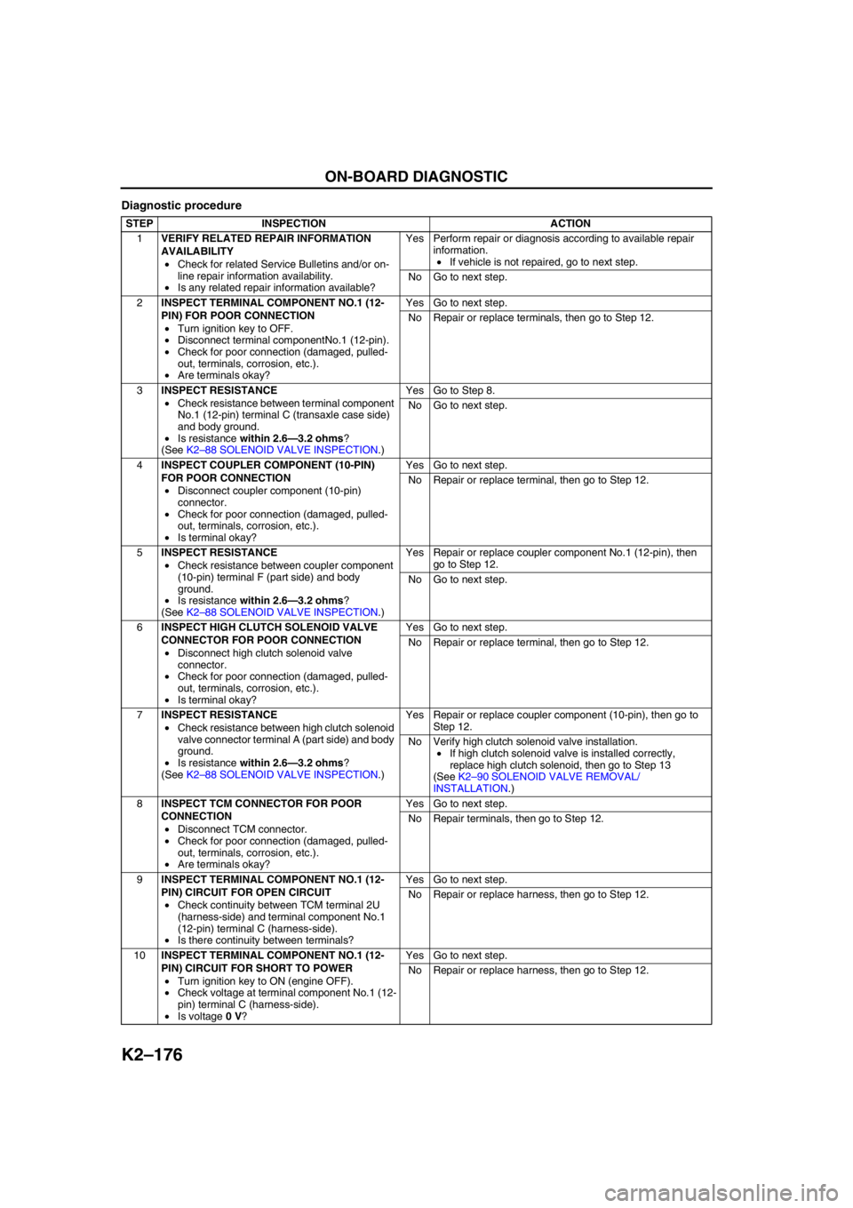
Diagnostic procedure
STEP INSPECTION ACTION
1VERIFY RELATED REPAIR INFORMATION
AVAILABILITY
•Check for related Service Bulletins and/or on-
line repair information availability.
•Is any related repair information available?Yes Perform repair or diagnosis according to available repair
information.
•If vehicle is not repaired, go to next step.
No Go to next step.
2INSPECT TERMINAL COMPONENT NO.1 (12-
PIN) FOR POOR CONNECTION
•Turn ignition key to OFF.
•Disconnect terminal componentNo.1 (12-pin).
•Check for poor connection (damaged, pulled-
out, terminals, corrosion, etc.).
•Are terminals okay?Yes Go to next step.
No Repair or replace terminals, then go to Step 12.
3INSPECT RESISTANCE
•Check resistance between terminal component
No.1 (12-pin) terminal C (transaxle case side)
and body ground.
•Is resistance within 2.6—3.2 ohms?
(See K2–88 SOLENOID VALVE INSPECTION.)Yes Go to Step 8.
No Go to next step.
4INSPECT COUPLER COMPONENT (10-PIN)
FOR POOR CONNECTION
•Disconnect coupler component (10-pin)
connector.
•Check for poor connection (damaged, pulled-
out, terminals, corrosion, etc.).
•Is terminal okay?Yes Go to next step.
No Repair or replace terminal, then go to Step 12.
5INSPECT RESISTANCE
•Check resistance between coupler component
(10-pin) terminal F (part side) and body
ground.
•Is resistance within 2.6—3.2 ohms?
(See K2–88 SOLENOID VALVE INSPECTION.)Yes Repair or replace coupler component No.1 (12-pin), then
go to Step 12.
No Go to next step.
6INSPECT HIGH CLUTCH SOLENOID VALVE
CONNECTOR FOR POOR CONNECTION
•Disconnect high clutch solenoid valve
connector.
•Check for poor connection (damaged, pulled-
out, terminals, corrosion, etc.).
•Is terminal okay?Yes Go to next step.
No Repair or replace terminal, then go to Step 12.
7INSPECT RESISTANCE
•Check resistance between high clutch solenoid
valve connector terminal A (part side) and body
ground.
•Is resistance within 2.6—3.2 ohms?
(See K2–88 SOLENOID VALVE INSPECTION.)Yes Repair or replace coupler component (10-pin), then go to
Step 12.
No Verify high clutch solenoid valve installation.
•If high clutch solenoid valve is installed correctly,
replace high clutch solenoid, then go to Step 13
(See K2–90 SOLENOID VALVE REMOVAL/
INSTALLATION.)
8INSPECT TCM CONNECTOR FOR POOR
CONNECTION
•Disconnect TCM connector.
•Check for poor connection (damaged, pulled-
out, terminals, corrosion, etc.).
•Are terminals okay?Yes Go to next step.
No Repair terminals, then go to Step 12.
9INSPECT TERMINAL COMPONENT NO.1 (12-
PIN) CIRCUIT FOR OPEN CIRCUIT
•Check continuity between TCM terminal 2U
(harness-side) and terminal component No.1
(12-pin) terminal C (harness-side).
•Is there continuity between terminals?Yes Go to next step.
No Repair or replace harness, then go to Step 12.
10INSPECT TERMINAL COMPONENT NO.1 (12-
PIN) CIRCUIT FOR SHORT TO POWER
•Turn ignition key to ON (engine OFF).
•Check voltage at terminal component No.1 (12-
pin) terminal C (harness-side).
•Is voltage 0 V?Yes Go to next step.
No Repair or replace harness, then go to Step 12.
Page 592 of 909
ON-BOARD DIAGNOSTIC
K2–177
K2
End Of Sie
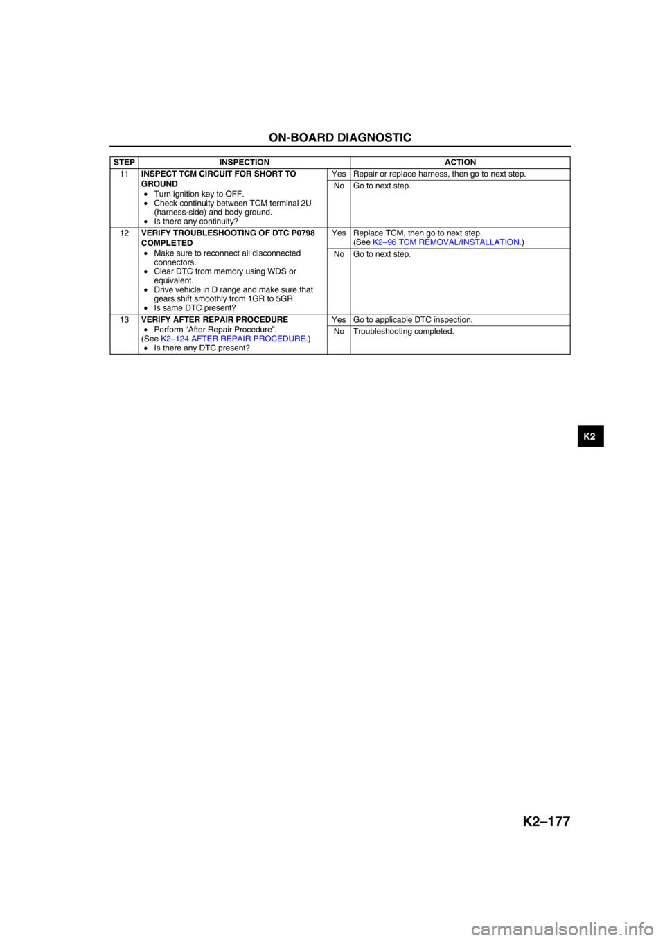
11INSPECT TCM CIRCUIT FOR SHORT TO
GROUND
•Turn ignition key to OFF.
•Check continuity between TCM terminal 2U
(harness-side) and body ground.
•Is there any continuity?Yes Repair or replace harness, then go to next step.
No Go to next step.
12VERIFY TROUBLESHOOTING OF DTC P0798
COMPLETED
•Make sure to reconnect all disconnected
connectors.
•Clear DTC from memory using WDS or
equivalent.
•Drive vehicle in D range and make sure that
gears shift smoothly from 1GR to 5GR.
•Is same DTC present?Yes Replace TCM, then go to next step.
(See K2–96 TCM REMOVAL/INSTALLATION.)
No Go to next step.
13VERIFY AFTER REPAIR PROCEDURE
•Perform “After Repair Procedure”.
(See K2–124 AFTER REPAIR PROCEDURE.)
•Is there any DTC present?Yes Go to applicable DTC inspection.
No Troubleshooting completed. STEP INSPECTION ACTION
Page 593 of 909

K2–178
ON-BOARD DIAGNOSTIC
DTC P1710A6E577018901229
DTC P1710 GND return circuit malfunction
DETECTION
CONDITION•TCM detects open circuit in GND return signal line from solenoid valve.
Diagnostic support note:
•This is a diagnostic support DTC (monitored one per key cycle).
•MIL does not illuminate.
•PENDING CODE is not available.
•FREEZE FRAME DATA is not available.
•AT warning light does not indication.
•DTC is stored in TCM memory.
POSSIBLE
CAUSE•Open circuit between duty type solenoid valves terminal and TCM terminal 2P
•Damaged connector between solenoid valve and TCM
•TCM malfunction
A J 2PB TCM
CPU
CPUAT X
TCM
HARNESS SIDE CONNECTOR TERMINAL COMPONENT
NO.1(12-PIN)
HARNESS SIDE CONNECTOR
COUPLER COMPONENT
(10-PIN)
PART SIDE CONNECTORSOLENOID VALVE
SOLENOID VALVE
HARNESS SIDE CONNECTOR
Page 594 of 909
ON-BOARD DIAGNOSTIC
K2–179
K2
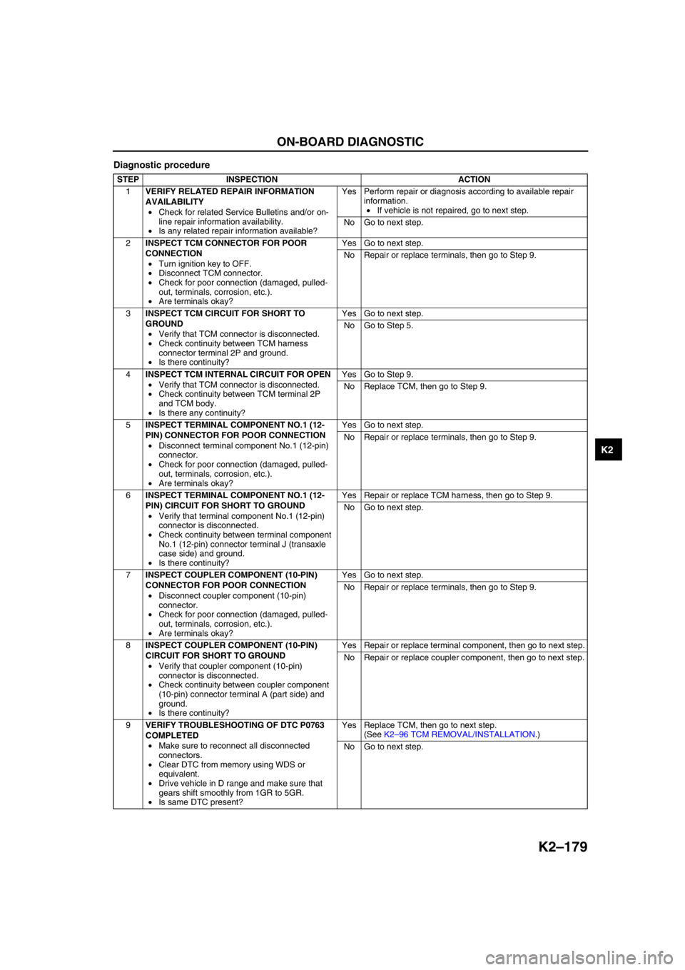
Diagnostic procedure
STEP INSPECTION ACTION
1VERIFY RELATED REPAIR INFORMATION
AVAILABILITY
•Check for related Service Bulletins and/or on-
line repair information availability.
•Is any related repair information available?Yes Perform repair or diagnosis according to available repair
information.
•If vehicle is not repaired, go to next step.
No Go to next step.
2INSPECT TCM CONNECTOR FOR POOR
CONNECTION
•Turn ignition key to OFF.
•Disconnect TCM connector.
•Check for poor connection (damaged, pulled-
out, terminals, corrosion, etc.).
•Are terminals okay?Yes Go to next step.
No Repair or replace terminals, then go to Step 9.
3INSPECT TCM CIRCUIT FOR SHORT TO
GROUND
•Verify that TCM connector is disconnected.
•Check continuity between TCM harness
connector terminal 2P and ground.
•Is there continuity?Yes Go to next step.
No Go to Step 5.
4INSPECT TCM INTERNAL CIRCUIT FOR OPEN
•Verify that TCM connector is disconnected.
•Check continuity between TCM terminal 2P
and TCM body.
•Is there any continuity?Yes Go to Step 9.
No Replace TCM, then go to Step 9.
5INSPECT TERMINAL COMPONENT NO.1 (12-
PIN) CONNECTOR FOR POOR CONNECTION
•Disconnect terminal component No.1 (12-pin)
connector.
•Check for poor connection (damaged, pulled-
out, terminals, corrosion, etc.).
•Are terminals okay?Yes Go to next step.
No Repair or replace terminals, then go to Step 9.
6INSPECT TERMINAL COMPONENT NO.1 (12-
PIN) CIRCUIT FOR SHORT TO GROUND
•Verify that terminal component No.1 (12-pin)
connector is disconnected.
•Check continuity between terminal component
No.1 (12-pin) connector terminal J (transaxle
case side) and ground.
•Is there continuity?Yes Repair or replace TCM harness, then go to Step 9.
No Go to next step.
7INSPECT COUPLER COMPONENT (10-PIN)
CONNECTOR FOR POOR CONNECTION
•Disconnect coupler component (10-pin)
connector.
•Check for poor connection (damaged, pulled-
out, terminals, corrosion, etc.).
•Are terminals okay?Yes Go to next step.
No Repair or replace terminals, then go to Step 9.
8INSPECT COUPLER COMPONENT (10-PIN)
CIRCUIT FOR SHORT TO GROUND
•Verify that coupler component (10-pin)
connector is disconnected.
•Check continuity between coupler component
(10-pin) connector terminal A (part side) and
ground.
•Is there continuity?Yes Repair or replace terminal component, then go to next step.
No Repair or replace coupler component, then go to next step.
9VERIFY TROUBLESHOOTING OF DTC P0763
COMPLETED
•Make sure to reconnect all disconnected
connectors.
•Clear DTC from memory using WDS or
equivalent.
•Drive vehicle in D range and make sure that
gears shift smoothly from 1GR to 5GR.
•Is same DTC present?Yes Replace TCM, then go to next step.
(See K2–96 TCM REMOVAL/INSTALLATION.)
No Go to next step.
Page 646 of 909
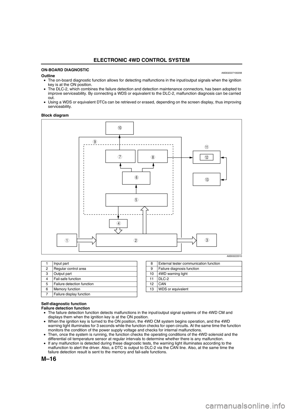
M–16
ELECTRONIC 4WD CONTROL SYSTEM
ON-BOARD DIAGNOSTICA6E632227100208Outline
•The on-board diagnostic function allows for detecting malfunctions in the input/output signals when the ignition
key is at the ON position.
•The DLC-2, which combines the failure detection and detection maintenance connectors, has been adopted to
improve serviceability. By connecting a WDS or equivalent to the DLC-2, malfunction diagnosis can be carried
out.
•Using a WDS or equivalent DTCs can be retrieved or erased, depending on the screen display, thus improving
serviceability.
Block diagram
.
Self-diagnostic function
Failure detection function
•The failure detection function detects malfunctions in the input/output signal systems of the 4WD CM and
displays them when the ignition key is at the ON position.
•When the ignition key is turned to the ON position, the 4WD CM system begins operation, and the 4WD
warning light illuminates for 3 seconds while the function checks for open circuits. At the same time the function
monitors the condition of the power supply voltage and checks for internal malfunctions.
•Then, once the system is running, the function checks the operating conditions of the 4WD solenoid and the
differential oil temperature sensor at regular intervals to determine whether there is any malfunction.
•If any malfunction is detected during these diagnostic tests, the warning light illuminates according to the
malfunction to alert the driver. Also, a DTC is output to DLC-2 via the CAN line. Also, at the same time the
failure detection result is sent to the memory and fail-safe functions.
9
87
5
4
3
10
13
11
12
6
12
A6E63222010
1 Input part
2 Regular control area
3 Output part
4 Fail-safe function
5 Failure detection function
6 Memory function
7 Failure display function8 External tester communication function
9 Failure diagnosis function
10 4WD warning light
11 DLC-2
12 CAN
13 WDS or equivalent
Page 647 of 909
ELECTRONIC 4WD CONTROL SYSTEM
M–17
M
Memory function
•This function stores DTCs for malfunctions of the input/output signal systems as determined by the failure
detection function. Once a DTC is stored, it is not cleared even if the input/output signal system malfunction
returns to normal when the ignition key is turned to the LOCK position (engine OFF).
•Since DTCs are stored in the non-volatile memory inside the 4WD CM, they are not cleared even if the battery
is disconnected. Therefore, it is necessary to clear the memory when maintenance has been completed. For
clearing DTCs, refer to the procedures in the Workshop Manual.
•When inspecting DTCs using a WDS or equivalent, only one memory stored DTC at a time can be displayed.
Therefore, when multiple DTCs have been stored, it is necessary to inspect for DTCs again after repairing and
clearing the present DTC to ensure that there are no more DTCs present in the memory.
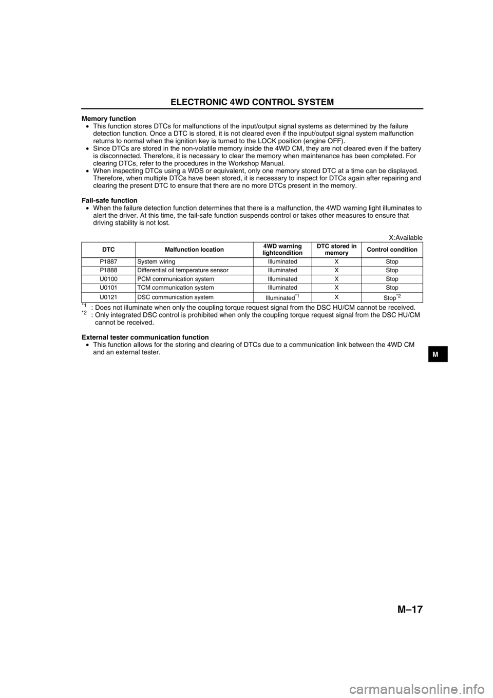
Fail-safe function
•When the failure detection function determines that there is a malfunction, the 4WD warning light illuminates to
alert the driver. At this time, the fail-safe function suspends control or takes other measures to ensure that
driving stability is not lost.
X:Available
*1: Does not illuminate when only the coupling torque request signal from the DSC HU/CM cannot be received.*2: Only integrated DSC control is prohibited when only the coupling torque request signal from the DSC HU/CM
cannot be received.
External tester communication function
•This function allows for the storing and clearing of DTCs due to a communication link between the 4WD CM
and an external tester.
End Of Sie
DTC Malfunction location4WD warning
lightconditionDTC stored in
memoryControl condition
P1887 System wiring Illuminated X Stop
P1888 Differential oil temperature sensor Illuminated X Stop
U0100 PCM communication system Illuminated X Stop
U0101 TCM communication system Illuminated X Stop
U0121 DSC communication system
Illuminated
*1X
Stop*2