key MAZDA 6 2002 Suplement Repair Manual
[x] Cancel search | Manufacturer: MAZDA, Model Year: 2002, Model line: 6, Model: MAZDA 6 2002Pages: 909, PDF Size: 17.16 MB
Page 696 of 909

M–66
ELECTRONIC 4WD CONTROL SYSTEM
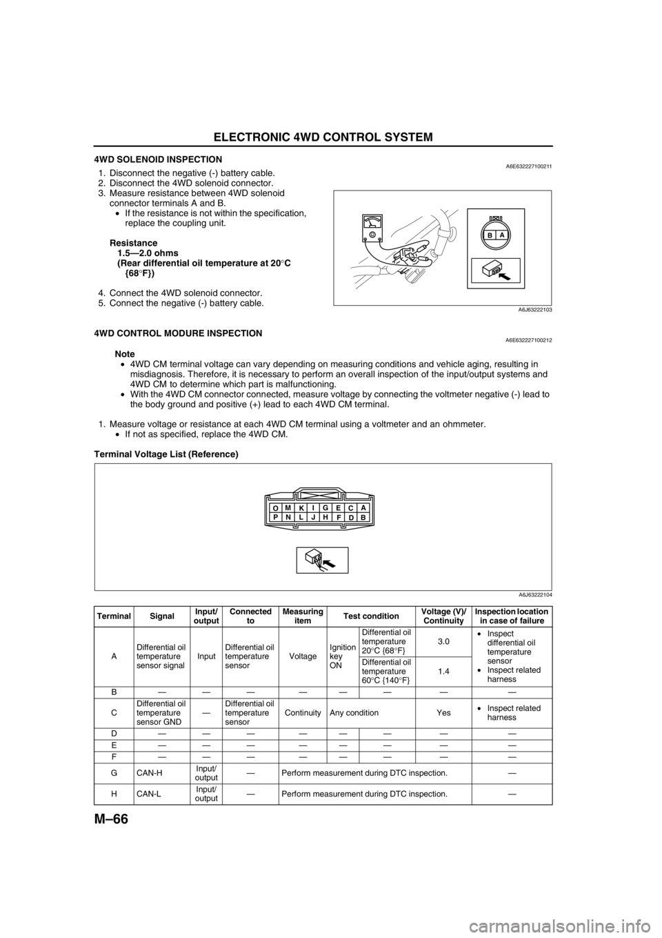
4WD SOLENOID INSPECTIONA6E6322271002111. Disconnect the negative (-) battery cable.
2. Disconnect the 4WD solenoid connector.
3. Measure resistance between 4WD solenoid
connector terminals A and B.
•If the resistance is not within the specification,
replace the coupling unit.
Resistance
1.5—2.0 ohms
(Rear differential oil temperature at 20°C
{68°F})
4. Connect the 4WD solenoid connector.
5. Connect the negative (-) battery cable.
End Of Sie
4WD CONTROL MODURE INSPECTIONA6E632227100212
Note
•4WD CM terminal voltage can vary depending on measuring conditions and vehicle aging, resulting in
misdiagnosis. Therefore, it is necessary to perform an overall inspection of the input/output systems and
4WD CM to determine which part is malfunctioning.
•With the 4WD CM connector connected, measure voltage by connecting the voltmeter negative (-) lead to
the body ground and positive (+) lead to each 4WD CM terminal.
1. Measure voltage or resistance at each 4WD CM terminal using a voltmeter and an ohmmeter.
•If not as specified, replace the 4WD CM.
Terminal Voltage List (Reference)
A
B
A6J63222103
Terminal SignalInput/
outputConnected
toMeasuring
itemTest conditionVoltage (V)/
ContinuityInspection location
in case of failure
ADifferential oil
temperature
sensor signalInputDifferential oil
temperature
sensorVoltageIgnition
key
ONDifferential oil
temperature
20°C {68°F}3.0•Inspect
differential oil
temperature
sensor
•Inspect related
harness Differential oil
temperature
60°C {140°F}1.4
B——— ——— — —
CDifferential oil
temperature
sensor GND—Differential oil
temperature
sensorContinuity Any condition Yes•Inspect related
harness
D——— ——— — —
E——— ——— — —
F——— ——— — —
GCAN-HInput/
output—Perform measurement during DTC inspection.—
HCAN-LInput/
output—Perform measurement during DTC inspection.—
A
B C
D E
F G
H I
J K
L M
N O
P
A6J63222104
Page 697 of 909

ELECTRONIC 4WD CONTROL SYSTEM
M–67
M
End Of Sie
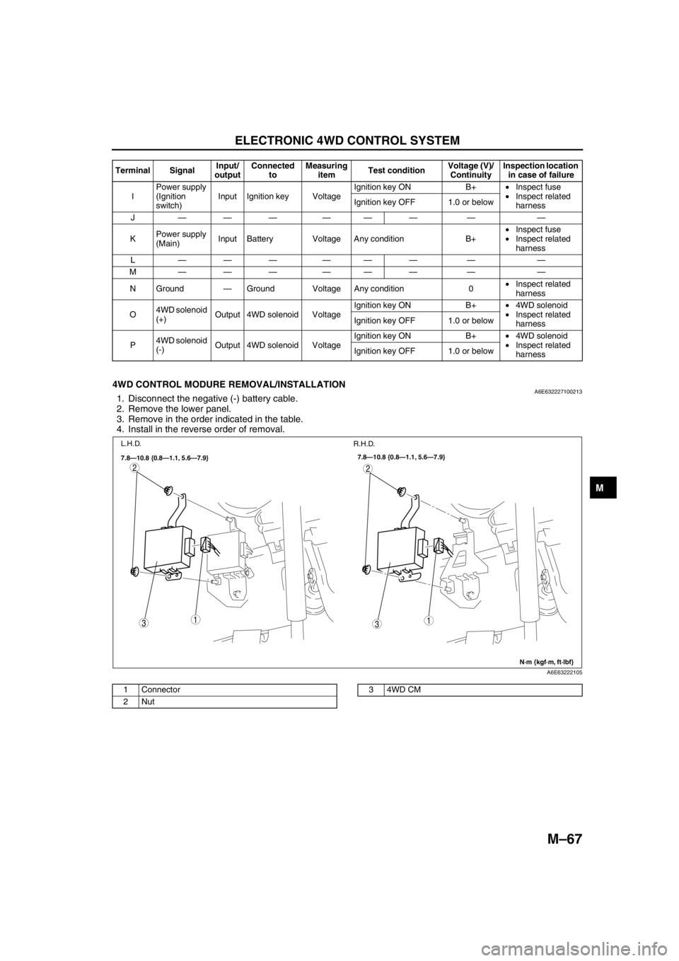
4WD CONTROL MODURE REMOVAL/INSTALLATIONA6E6322271002131. Disconnect the negative (-) battery cable.
2. Remove the lower panel.
3. Remove in the order indicated in the table.
4. Install in the reverse order of removal.
.
End Of Sie
IPower supply
(Ignition
switch)Input Ignition key VoltageIgnition key ON B+•Inspect fuse
•Inspect related
harness Ignition key OFF 1.0 or below
J——— ——— — —
KPower supply
(Main)Input Battery Voltage Any condition B+•Inspect fuse
•Inspect related
harness
L——— ——— — —
M——— ——— — —
N Ground—Ground Voltage Any condition 0•Inspect related
harness
O4WD solenoid
(+)Output 4WD solenoid VoltageIgnition key ON B+•4WD solenoid
•Inspect related
harness Ignition key OFF 1.0 or below
P4WD solenoid
(-)Output 4WD solenoid VoltageIgnition key ON B+•4WD solenoid
•Inspect related
harness Ignition key OFF 1.0 or below Terminal SignalInput/
outputConnected
toMeasuring
itemTest conditionVoltage (V)/
ContinuityInspection location
in case of failure
31
2
31
2
7.8—10.8 {0.8—1.1, 5.6—7.9}
N·m {kgf·m, ft·lbf} 7.8—10.8 {0.8—1.1, 5.6—7.9}
L.H.D.
R.H.D.
A6E63222105
1 Connector
2Nut34WD CM
Page 706 of 909

M–76
ON-BOARD DIAGNOSTIC
ELECTRONIC 4WD CONTROL SYSTEM ON-BOARD DIAGNOSISA6E637027100202Reading DTCs Procedure
1. Connect WDS or equivalent to the vehicle DLC-2
16-pin connector.
2. Retrieve DTC by WDS or equivalent.
•If a DTC is displayed, proceed with inspection
steps for that DTC.
3. After repair, clear DTCs stored in the 4WD CM by
referring to the Clearing DTCs Procedure.
Clearing DTCs Procedures
1. Connect WDS or equivalent to the vehicle DLC-2
16-pin connector.
2. Clear DTCs by WDS or equivalent.
3. Turn the ignition key to OFF.
4. Perform the DTC inspection again, and verify that
no DTC appears.
5. Disconnect the WDS or equivalent.
DTC Table
End Of Sie
DLC-2
DLC-2
L.H.D.
R.H.D.
A6E63702005
DLC-2
DLC-2
L.H.D.
R.H.D.
A6E63702005
DTC
Diagnosis system component Page
WDS or equivalent
P1887 System wiring (See M–77 DTC P1887)
P1888 Differential oil temperature sensor (See M–79 DTC P1888)
U0100 PCM communication (See M–80 DTC U0100)
U0101 TCM communication (See M–80 DTC U0101)
U0121 ABS/DSC communication (See M–80 DTC U0121)
Page 707 of 909

ON-BOARD DIAGNOSTIC
M–77
M
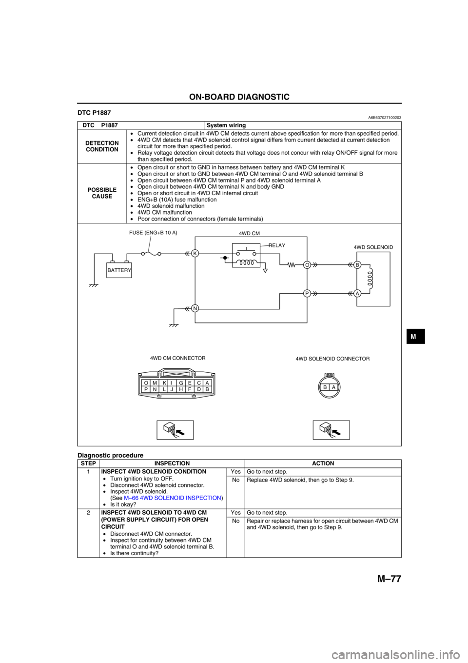
DTC P1887A6E637027100203
Diagnostic procedure
DTC P1887 System wiring
DETECTION
CONDITION•Current detection circuit in 4WD CM detects current above specification for more than specified period.
•4WD CM detects that 4WD solenoid control signal differs from current detected at current detection
circuit for more than specified period.
•Relay voltage detection circuit detects that voltage does not concur with relay ON/OFF signal for more
than specified period.
POSSIBLE
CAUSE•Open circuit or short to GND in harness between battery and 4WD CM terminal K
•Open circuit or short to GND between 4WD CM terminal O and 4WD solenoid terminal B
•Open circuit between 4WD CM terminal P and 4WD solenoid terminal A
•Open circuit between 4WD CM terminal N and body GND
•Open or short circuit in 4WD CM internal circuit
•ENG+B (10A) fuse malfunction
•4WD solenoid malfunction
•4WD CM malfunction
•Poor connection of connectors (female terminals)
STEP INSPECTION ACTION
1INSPECT 4WD SOLENOID CONDITION
•Turn ignition key to OFF.
•Disconnect 4WD solenoid connector.
•Inspect 4WD solenoid.
(See M–66 4WD SOLENOID INSPECTION)
•Is it okay?Yes Go to next step.
No Replace 4WD solenoid, then go to Step 9.
2INSPECT 4WD SOLENOID TO 4WD CM
(POWER SUPPLY CIRCUIT) FOR OPEN
CIRCUIT
•Disconnect 4WD CM connector.
•Inspect for continuity between 4WD CM
terminal O and 4WD solenoid terminal B.
•Is there continuity?Yes Go to next step.
No Repair or replace harness for open circuit between 4WD CM
and 4WD solenoid, then go to Step 9.
A A
B C
D E
F G
H I
J K
L M
N O
PB K
O B
A
N P BATTERYFUSE (ENG+B 10 A)
4WD CM
4WD CM CONNECTOR4WD SOLENOID
4WD SOLENOID CONNECTOR RELAY
Page 708 of 909

M–78
ON-BOARD DIAGNOSTIC
End Of Sie
3INSPECT 4WD SOLENOID TO 4WD CM
(POWER SUPPLY CIRCUIT) FOR SHORT TO
GROUND
•Inspect for continuity between 4WD CM
terminal O and ground.
•Is there continuity?Yes Repair or replace harness for short to ground between 4WD
CM and 4WD solenoid, then go to Step 9.
No Go to next step.
4INSPECT 4WD SOLENOID TO 4WD CM
(GROUND CIRCUIT) FOR OPEN CIRCUIT
•Inspect for continuity between 4WD CM
terminal P and 4WD solenoid terminal A.
•Is there continuity?Yes Replace 4WD CM, then go to next step.
No Repair or replace harness for open circuit between 4WD CM
and 4WD solenoid, then go to Step 9.
5INSPECT 4WD CM POWER SUPPLY CIRCUIT
FOR OPEN CIRCUIT
•Measure voltage between 4WD CM terminal
K and ground.
•Is voltage B+?Yes Replace 4WD CM, then go to Step 9.
No Go to next step.
6INSPECT 4WD CM TO BATTERY FOR OPEN
CIRCUIT
•Disconnect 4WD CM connector and battery
positive terminal.
•Inspect for continuity between 4WD CM
terminal K and battery positive terminal.
•Is there continuity?Yes Go to next step.
No Repair or replace harness for open circuit between 4WD CM
and battery positive terminal, then go to Step 9.
7INSPECT 4WD CM TO BATTERY FOR SHORT
TO GROUND
•Inspect for continuity between 4WD CM
terminal K and ground.
•Is there continuity?Yes Repair or replace harness for short to ground between 4WD
CM and battery positive terminal, then go to Step 9.
No Replace 4WD CM, then go to step 9.
8INSPECT FUSE CONDITION
•Turn ignition key to OFF.
•Is ENG+B fuse (10A) okay?Yes Go to next step.
No Replace fuse, then go to Step 9.
9VERIFY TROUBLESHOOTING COMPLETED
•Make sure to reconnect all disconnected
connectors.
•Clear DTC from memory.
(See M–76 Clearing DTCs Procedures)
•Drive vehicle.
•Is the same DTC present?Yes Replace 4WD CM, then go to next step.
No Go to next step.
10VERIFY AFTER REPAIR PROCEDURE
•Is there any other DTC present?Yes Go to applicable DTC inspection.
No Troubleshooting completed. STEP INSPECTION ACTION
Page 709 of 909

ON-BOARD DIAGNOSTIC
M–79
M
DTC P1888A6E637027100204
Diagnostic procedure
DTC P1888 Differential oil temperature sensor
DETECTION
CONDITION•Differential oil temperature sensor voltage monitor circuit detects abnormal input voltage.
POSSIBLE
CAUSE•Open circuit, or short to battery or GND between 4WD CM terminal A and differential oil temperature
sensor terminal A
•Open circuit or short to battery between 4WD CM terminal C and differential oil temperature sensor
terminal B
•Differential oil temperature sensor malfunction
•4WD CM malfunction
•Poor connection of connectors (female terminals)
STEP INSPECTION ACTION
1INSPECT DIFFERENTIAL OIL
TEMPERATURE SENSOR CONDITION
•Turn ignition key to OFF.
•Disconnect differential oil temperature
sensor connector.
•Is it okay?Yes Go to next step.
No Replace differential oil temperature sensor, then go to Step
7.
2INSPECT 4WD CM TO DIFFERENTIAL OIL
TEMPERATURE SENSOR FOR OPEN
CIRCUIT
•Disconnect 4WD CM connector.
•Inspect for continuity between 4WD CM
terminal A and differential oil temperature
sensor terminal A.
•Is there continuity?Yes Go to next step.
No Repair or replace harness for open circuit between 4WD CM
and differential oil temperature sensor, then go to Step 7.
3INSPECT 4WD CM TO DIFFERENTIAL OIL
TEMPERATURE SENSOR FOR SHORT TO
POWER
•Inspect voltage between 4WD CM terminal A
and ground.
•Is voltage B+?Yes Repair or replace harness for short to power between 4WD
CM and differential oil temperature sensor, then go to Step
7.
No Go to next step.
A B A
B C
D E
F G
H I
J K
L M
N O
PA
C A
B
4WD CM CONNECTOR4WD CM
DIFFERENTIAL OIL
TEMPERATURE SENSOR
DIFFERENTIAL OIL TEMPERATURE
SENSOR CONNECTOR
Page 713 of 909

TROUBLESHOOTING
M–83
M
Diagnostic procedure
End Of Sie
NO.2 TIGHT CORNER BRAKINGA6E638027100205
Diagnostic procedure
STEP INSPECTION ACTION
1VERIFY DSC, PCM, TCM, AND 4WD SYSTEM
DTCs
•Verify DSC, PCM, TCM, and 4WD system
DTCs using WDS or equivalent.
•Are there any DTCs present?Yes Go to applicable DTC inspection.
No Go to next step.
2VERIFY TIRE AIR PRESSURE
•Inspect tire air pressure.
•Is it within specification?Yes Go to next step.
No Adjust tire air pressure, then go to next step.
3COMPARE WITH SAME MODEL TIRES
•Install tires of the same model.
•Perform simulation driving.
•Does malfunction recur?Yes Go to next step.
No 4WD system is okay.
4COMPARE WITH SAME MODEL VEHICLE
•Install tires of malfunctioning vehicle to
another same model vehicle.
•Perform simulation driving.
•Does malfunction recur?Yes 4WD system is okay.
No Go to next step.
5INSPECT 4WD SOLENOID
•Inspect 4WD solenoid.
(See M–66 4WD SOLENOID INSPECTION)
•Is coupling component solenoid okay?Yes Inspect harness between 4WD solenoid and 4WD CM, then
go to next step.
No Replace coupling component.
6INSPECT WHEEL ALIGNMENT
•Inspect wheel alignment.
•Is it okay?Yes Replace coupling component.
No Inspect wheel alignment, and adjust it if necessary.
2 Tight corner braking
[TROUBLESHOOTING HINTS]
•Because the coupling component locks up easily (similar to direct 4WD), rotational difference between the front
and rear wheels cannot be absorbed and brake-like phenomenon occurs.
•Due to the coupling component construction, slight tight corner braking effect occurs during tight cornering on a
paved road. (4WD system is okay. Compare with another same model vehicle to determine malfunction.)
•Coupling component malfunction
•4WD solenoid malfunction
STEP INSPECTION ACTION
1VERIFY DSC, PCM, TCM, AND 4WD SYSTEM
DTCS
•Verify DSC, PCM, TCM, and 4WD system
DTCs using WDS or equivalent.
•Are there any DTCs present?Yes Go to applicable DTC inspection.
No Go to next step.
2VERIFY TIRE AIR PRESSURE
•Inspect tire air pressure.
•Is it within specification?Yes Go to next step.
No Adjust tire air pressure, then go to next step.
3INSPECT ABS WHEEL-SPEED SENSOR
•Inspect ABS wheel-speed sensor.
•Is it okay?Yes Go to next step.
No Repair or replace malfunctioning part.
4COMPARE WITH SAME MODEL VEHICLE
•Perform simulation driving with another
same model vehicle.
•Does malfunction recur on the same model
vehicle?Yes 4WD system is okay.
No Go to next step.
5PERFORM SIMULATION DRIVING WITH 4WD
SOLENOID CONNECTOR DISCONNECTED
•Turn ignition key OFF.
•Disconnect 4WD solenoid connector.
•Perform simulation driving. (Clear DTC after
simulation driving.)
•Does malfunction recur?Yes Replace coupling component.
No Go to next step.
Page 758 of 909

ON-BOARD DIAGNOSTIC
P–25
P
End Of Sie
TCSOUTD
(Torque reduction request
value)PERCENTAGE•Torque reduction is not
requested: 0 %
•Torque reduction is
requested: Changes
between 0 % and 100 %Inspect DSC HU/CM.
—
TPI (with DSC only)
(Throttle position signal input)PERCENTAGE•Closed throttle position: 0
•Wide open throttle: Changes
between 1 and 7Inspect PCM and
throttle position
sensor.—
ABS_VOLT
(System battery voltage value)VOLTAGE•Ignition key at ON: B+
•Idle: Approx. 14—16 VInspect power supply
circuit.ABS (ABS/
TCS): Z
DSC: G
ACCLMTR
*
(Accelerometer)ACCELERATION•Vehicle is stopped or driving
at a constant speed: 0 G.
•Vehicle is driving at a
acceleration: Changes
between 0— –1.28 G.
•Vehicle is driving at a
deceleration: Changes
between 0—1.27 G.Inspect combine
sensor.
V PID Name
(Definition)Unit/Condition Condition/Specification ActionABS (ABS/
TCS) HU/CM or
DSC HU/CM
terminal
Page 760 of 909

ON-BOARD DIAGNOSTIC
P–27
P
Diagnostic procedure
End Of Sie
DTC C1949, C1950A6E697067650203
Caution
•When attaching the tester lead to the DSC HU/CM connector, the SST (49 G066 004) must be used.
STEP INSPECTION ACTION
1CHECK FOR PCM FOR DTCs
•Turn ignition key to OFF.
•Connect WDS or equivalent to DLC-2
•Turn ignition key to ON (engine OFF).
•Is DTC for engine control system obtained?Yes Follow inspection procedures for engine control system.
No Go to next step.
2MONITOR CAN SIGNAL
•Access PID RPM and TP using WDS or
equivalent.
•Are engine speed and throttle position within
specification?Yes Go to next step.
No Follow inspection procedures for engine control system.
3VERIFY TROUBLESHOOTING COMPLETED
•Make sure to reconnect all disconnected
connectors.
•Clear DTC from memory.
•Start engine.
•Is same DTC present?Yes Replace DSC HU/CM, then go to next step.
No Troubleshooting completed.
DTC C1949, C1950 Combine sensor (forward G-sensor)
DETECTION
CONDITION•C1949:
—Monitor voltage of forward-G sensor is detected at 4.5 V or more, or 0.5 V or less.
—Monitor voltage difference of 0.4 V or more within 1 cycle is detected 8 times in 1 second.
•C1950:
—Forward-G sensor 0-point correction value is default or more
—Output voltage value from G sensor remains absolutely unchanged
—Difference between estimated G-force calculated from 2 channels exceeds specification
POSSIBLE
CAUSE•Open circuit in harness between combine sensor terminal C and DSC HU/CM terminal P
•Open circuit, short to power, or short to ground in harness between DSC HU/CM terminal V and
combine sensor terminal A
•Open circuit, short to power, or short to ground in harness between DSC HU/CM terminal S and
combine sensor terminal F
•Open circuit in harness between combine sensor terminal E and DSC HU/CM terminal Y
•Malfunction of combine sensor
Page 761 of 909

P–28
ON-BOARD DIAGNOSTIC
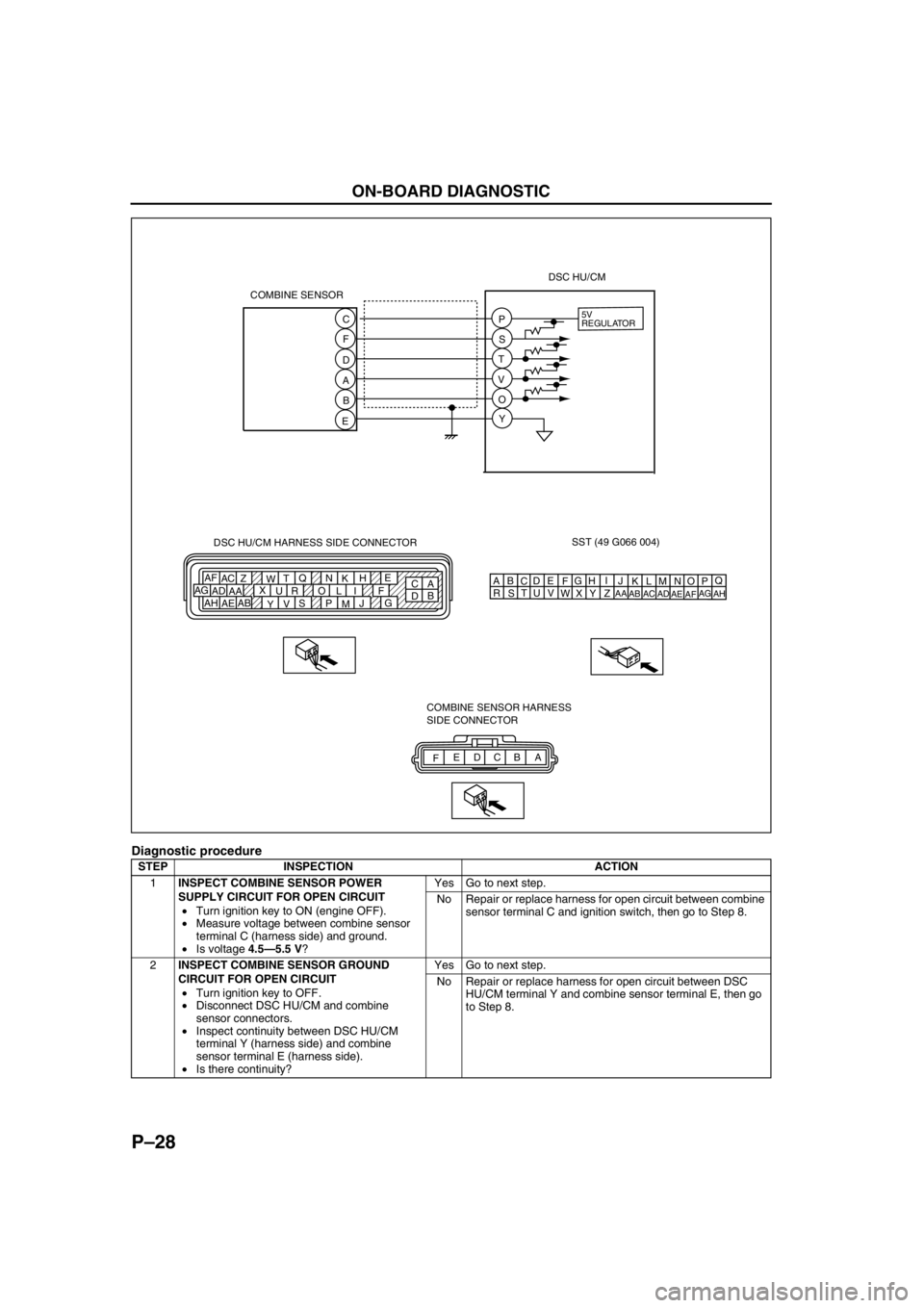
Diagnostic procedure
STEP INSPECTION ACTION
1INSPECT COMBINE SENSOR POWER
SUPPLY CIRCUIT FOR OPEN CIRCUIT
•Turn ignition key to ON (engine OFF).
•Measure voltage between combine sensor
terminal C (harness side) and ground.
•Is voltage 4.5—5.5 V?Yes Go to next step.
No Repair or replace harness for open circuit between combine
sensor terminal C and ignition switch, then go to Step 8.
2INSPECT COMBINE SENSOR GROUND
CIRCUIT FOR OPEN CIRCUIT
•Turn ignition key to OFF.
•Disconnect DSC HU/CM and combine
sensor connectors.
•Inspect continuity between DSC HU/CM
terminal Y (harness side) and combine
sensor terminal E (harness side).
•Is there continuity?Yes Go to next step.
No Repair or replace harness for open circuit between DSC
HU/CM terminal Y and combine sensor terminal E, then go
to Step 8.
SST (49 G066 004)
AQ
B
CDE
FG
HI
J DSC HU/CM HARNESS SIDE CONNECTOR
A
C E
H
K N Q
T
W Z AC AF
F I L O R U X
AA AD AG
G
J
M P S
V
Y AB
AE AHB
DKN
T
WZ
AC
AFLO
RU
XAA
ADAGMP
SV
YAB
AEAH 5V
REGULATOR
COMBINE SENSOR
FA B C D E COMBINE SENSOR HARNESS
SIDE CONNECTOR C
F
D
A
B
EP
S
T
V
O
YDSC HU/CM