wiring MAZDA 6 2002 Suplement Manual PDF
[x] Cancel search | Manufacturer: MAZDA, Model Year: 2002, Model line: 6, Model: MAZDA 6 2002Pages: 909, PDF Size: 17.16 MB
Page 382 of 909

F2–230
TROUBLESHOOTING
Cooling Fan No.1/Cooling Fan No.2 Control System Inspection
Cooling fan No.1/cooling fan No.2 system operation
Cooling fan relay No.2
1. Connect the WDS or equivalent to DLC-2.
2. Verify that ECT PID is below main fan operating temperature.
3. Verify that A/C switch and fan switch are off.
4. Turn the engine switch to ON.
5. Verify that the cooling fan No.2 is not operating.
•If the cooling fan No.2 is operating:
(1) Select FAN PID.
(2) Send OFF and verify the cooling fan No.2 is off.
•If the cooling fan No.2 is on, inspect the following.
—Cooling fan relay No.2 stuck in closed position
—Short to GND circuit between cooling fan relay No.2 and PCM terminal 76
—Short to power in circuit at cooling fan relay No.2
—DTC for ECT sensor (P0117, P0118)
•If the cooling fan relay No.2 is off, inspect the following.
—Short to GND circuit between refrigerant pressure switch and PCM terminal 84
—DTC for ECT sensor (P0117, P0118)
6. Start the engine.
7. Verify that the cooling fan No.2 is operating when engine is hot.
•If the cooling fan No.2 does not operate, perform the following.
1. Connect WDS or equivalent to the DLC-2.
2. Select FAN PID.
3. Operate cooling fan No.2 by sending ON command.
4. Inspect if the operation sound is heard from the cooling fan relay No.2.
•If the operation sound is heard, inspect the wiring harness, connectors and cooling fan motor No.2.
•If the operation sound is not heard, inspect cooling fan relay No.2 and open circuit wiring harness
and connectors.
8. Turn the A/C switch and fan switch on.
9. Verify that cooling fan No.2 is operating.
•If fan does not operate, inspect A/C system.
Cooling fan relay No.1
1. Verify that A/C switch and fan switch are off.
2. Start the engine and let it idle.
3. Verify that the cooling fan No.1 is not operating.
•If cooling fan No.1 is operating, inspect for the following.
—Cooling fan relay No.1 is stuck in closed position.
—Short to power in circuit between cooling fan relay No.1 and cooling fan No.1
—Short to GND in circuit between refrigerant pressure switch and PCM terminal 84
—Short to GND circuit between cooling fan relay No.1 and PCM terminal 102
4. Turn the A/C switch and fan switch on.
5. Verify that the cooling fan No.1 is operating and operation sound of A/C compressor magnetic clutch is heard.
Engine conditionCooling fan
relay No.2Cooling fan
relay No.1
ECT below 100°C
{212°F}OFF OFF
ECT above 100°C
{212°F} (until below
97°C {207°F})ON OFF
ECT above 108°C
{228°F} (until below
105°C {230°F})ON ON
A/C and fan switches
are on.ON ON
ECT sensor
malfunctionON ON
Page 390 of 909
CHARGING SYSTEM
G–7
G
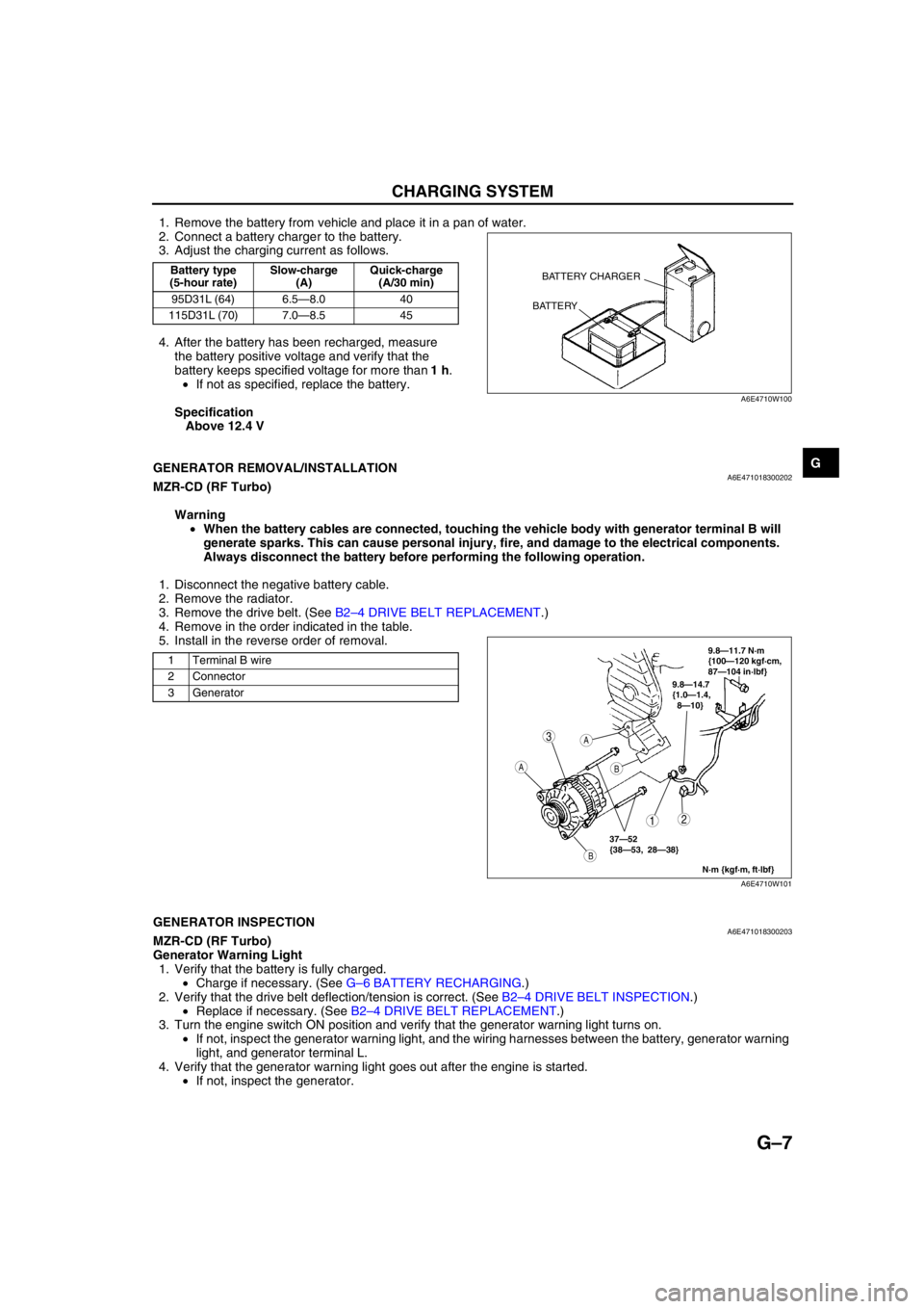
1. Remove the battery from vehicle and place it in a pan of water.
2. Connect a battery charger to the battery.
3. Adjust the charging current as follows.
4. After the battery has been recharged, measure
the battery positive voltage and verify that the
battery keeps specified voltage for more than 1 h.
•If not as specified, replace the battery.
Specification
Above 12.4 V
End Of Sie
GENERATOR REMOVAL/INSTALLATIONA6E471018300202MZR-CD (RF Turbo)
Warning
•When the battery cables are connected, touching the vehicle body with generator terminal B will
generate sparks. This can cause personal injury, fire, and damage to the electrical components.
Always disconnect the battery before performing the following operation.
1. Disconnect the negative battery cable.
2. Remove the radiator.
3. Remove the drive belt. (See B2–4 DRIVE BELT REPLACEMENT.)
4. Remove in the order indicated in the table.
5. Install in the reverse order of removal.
End Of SieGENERATOR INSPECTIONA6E471018300203MZR-CD (RF Turbo)
Generator Warning Light
1. Verify that the battery is fully charged.
•Charge if necessary. (See G–6 BATTERY RECHARGING.)
2. Verify that the drive belt deflection/tension is correct. (See B2–4 DRIVE BELT INSPECTION.)
•Replace if necessary. (See B2–4 DRIVE BELT REPLACEMENT.)
3. Turn the engine switch ON position and verify that the generator warning light turns on.
•If not, inspect the generator warning light, and the wiring harnesses between the battery, generator warning
light, and generator terminal L.
4. Verify that the generator warning light goes out after the engine is started.
•If not, inspect the generator.
Battery type
(5-hour rate)Slow-charge
(A)Quick-charge
(A/30 min)
95D31L (64) 6.5—8.0 40
115D31L (70) 7.0—8.5 45BATTERY CHARGER
BATTERY
A6E4710W100
1 Terminal B wire
2 Connector
3 Generator
3
12
A
B
A
B
9.8—14.7
{1.0—1.4,
8—10}
N·m {kgf·m, ft·lbf}
37—52
{38—53, 28—38}
9.8—11.7 N·m
{100—120 kgf·cm,
87—104 in·lbf}
A6E4710W101
Page 391 of 909
G–8
CHARGING SYSTEM
Generator
Voltage
1. Verify that the battery is fully charged.
•Charge if necessary. (See G–6 BATTERY RECHARGING.)
2. Inspect the drive belt deflection/tension.
(See B2–4 DRIVE BELT INSPECTION.)
•Replace if necessary. (See B2–4 DRIVE BELT REPLACEMENT.)
3. Turn off all electrical loads.
4. Turn the engine switch to start the engine and verify that the generator rotates smoothly without any noise
while the engine is running.
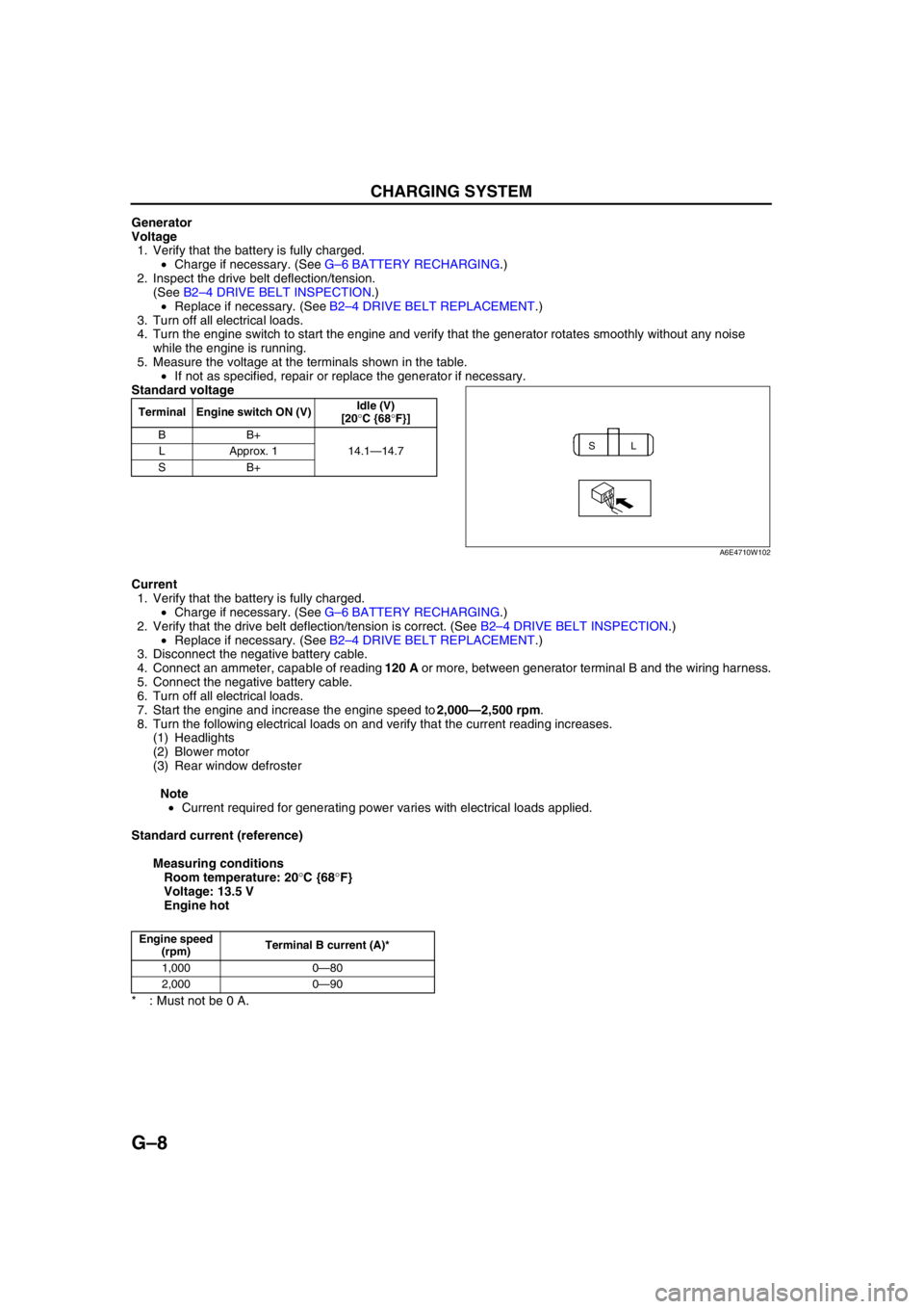
5. Measure the voltage at the terminals shown in the table.
•If not as specified, repair or replace the generator if necessary.
Standard voltage
Current
1. Verify that the battery is fully charged.
•Charge if necessary. (See G–6 BATTERY RECHARGING.)
2. Verify that the drive belt deflection/tension is correct. (See B2–4 DRIVE BELT INSPECTION.)
•Replace if necessary. (See B2–4 DRIVE BELT REPLACEMENT.)
3. Disconnect the negative battery cable.
4. Connect an ammeter, capable of reading 120 A or more, between generator terminal B and the wiring harness.
5. Connect the negative battery cable.
6. Turn off all electrical loads.
7. Start the engine and increase the engine speed to 2,000—2,500 rpm.
8. Turn the following electrical loads on and verify that the current reading increases.
(1) Headlights
(2) Blower motor
(3) Rear window defroster
Note
•Current required for generating power varies with electrical loads applied.
Standard current (reference)
Measuring conditions
Room temperature: 20°C {68°F}
Voltage: 13.5 V
Engine hot
* : Must not be 0 A.
End Of Sie
Terminal Engine switch ON (V)Idle (V)
[20°C {68°F}]
BB+
14.1—14.7 LApprox. 1
SB+
SL
A6E4710W102
Engine speed
(rpm)Terminal B current (A)*
1,000 0—80
2,000 0—90
Page 394 of 909

STARTING SYSTEM
G–11
G
STARTER INSPECTIONA6E471418400203MZR-CD (RF Turbo)
On-vehicle Inspection
1. Verify that the battery is fully charged.
•Charge if necessary. (See G–6 BATTERY RECHARGING.)
2. Crank the engine and verify that the starter rotates smoothly without any noise.
•If not as specified, inspect the following:
—Remove the starter, and inspect the magnetic switch and the starter.
—Inspect the related wiring harness and the engine switch.
No Load Test
1. Verify that the battery is fully charged.
•Charge if necessary. (See G–6 BATTERY RECHARGING.)
2. Connect the starter, battery, voltmeter and
ammeter as shown.
3. Operate the starter and verify that it rotates
smoothly.
4. Measure the voltage and current while the starter
is operating.
•If not as specified, replace the starter.
Specification
End Of Sie
Voltage (V)11
Current (A)Below 130
ENGINE
SWITCH
TERMINAL SB
M
STARTERVA
VOLTMETER
BATTERY
AMMETER
A6E4714W101
Page 416 of 909
![MAZDA 6 2002 Suplement Manual PDF K2–1
K2
K2AUTOMATIC TRANSAXLE [JA5AX-EL]
OUTLINE.............................................................. K2-3
FEATURES ........................................................ K2-3
SPECIFICATI MAZDA 6 2002 Suplement Manual PDF K2–1
K2
K2AUTOMATIC TRANSAXLE [JA5AX-EL]
OUTLINE.............................................................. K2-3
FEATURES ........................................................ K2-3
SPECIFICATI](/img/28/57057/w960_57057-415.png)
K2–1
K2
K2AUTOMATIC TRANSAXLE [JA5AX-EL]
OUTLINE.............................................................. K2-3
FEATURES ........................................................ K2-3
SPECIFICATIONS ............................................. K2-3
AUTOMATIC TRANSAXLE.................................. K2-4
OUTLINE ........................................................... K2-4
CROSS-SECTIONAL VIEW .............................. K2-6
ELECTRONIC CONTROL SYSTEM
STRUCTURAL VIEW...................................... K2-8
AUTOMATIC TRANSAXLE CONTROL SYSTEM
WIRING DIAGRAM ....................................... K2-10
AUTOMATIC TRANSAXLE BLOCK
DIAGRAM ..................................................... K2-11
AUTOMATIC TRANSAXLE DEVICE
RELATIONSHIP CHART .............................. K2-13
POWERTRAIN DESCRIPTION ....................... K2-15
TORQUE CONVERTER DESCRIPTION......... K2-40
OIL PUMP DESCRIPTION .............................. K2-41
CENTRIFUGAL BALANCE CLUTCH
DESCRIPTION ............................................. K2-42
CONTROL VALVE BODY DESCRIPTION ...... K2-43
TRANSAXLE FLUID TEMPERATURE
(TFT) SENSOR DESCRIPTION ................... K2-45
INPUT/TURBINE SPEED SENSOR
DESCRIPTION ............................................. K2-45
INTERMEDIATE SENSOR DESCRIPTION..... K2-46
VEHICLE SPEEDOMETER SENSOR
DESCRIPTION ............................................. K2-46
SOLENOID VALVE DESCRIPTION ................ K2-47
CONTROLLER AREA NETWORK (CAN)
DESCRIPTION ............................................. K2-50
TRANSAXLE CONTROL MODULE
(TCM) DESCRIPTION .................................. K2-51
SHIFT CONTROL DESCRIPTION .................. K2-51
MANUAL MODE SHIFT CONTROL
DESCRIPTION ............................................. K2-52
LINE PRESSURE CONTROL DESCRIPTION K2-54
FEEDBACK CONTROL DESCRIPTION ......... K2-57
N-D SELECT CONTROL DESCRIPTION........ K2-59
TORQUE CONVERTER CLUTCH
(TCC) CONTROL DESCRIPTION ................ K2-59
SLOPE MODE CONTROL DESCRIPTION ..... K2-63
ON-BOARD DIAGNOSTIC (OBD)
SYSTEM DESCRIPTION.............................. K2-64
COOLING SYSTEM DESCRIPTION ............... K2-69
LOCATION INDEX............................................. K2-70
AUTOMATIC TRANSAXLE LOCATION
INDEX ........................................................... K2-70
AUTOMATIC TRANSAXLE................................ K2-72
MECHANICAL SYSTEM TEST ....................... K2-72
ROAD TEST .................................................... K2-75AUTOMATIC TRANSAXLE FLUID
(ATF) INSPECTION ...................................... K2-78
AUTOMATIC TRANSAXLE FLUID
(ATF) REPLACEMENT ................................. K2-80
TRANSAXLE RANGE (TR) SWITCH
INSPECTION ................................................ K2-80
TRANSAXLE RANGE (TR) SWITCH
REMOVAL/INSTALLATION .......................... K2-81
TRANSAXLE RANGE (TR) SWITCH
ADJUSTMENT .............................................. K2-83
TRANSAXLE FLUID TEMPERATURE
(TFT) SENSOR INSPECTION ...................... K2-84
TRANSAXLE FLUID TEMPERATURE
(TFT) SENSOR REMOVAL/INSTALLATION K2-85
INPUT/TURBINE SPEED SENSOR
INSPECTION ................................................ K2-85
INPUT/TURBINE SPEED SENSOR
REMOVAL/INSTALLATION .......................... K2-86
INTERMEDIATE SENSOR INSPECTION ....... K2-86
INTERMEDIATE SENSOR
REMOVAL/INSTALLATION .......................... K2-86
VEHICLE SPEEDOMETER SENSOR
(VSS) INSPECTION...................................... K2-87
VEHICLE SPEEDOMETER SENSOR
(VSS) REMOVAL/INSTALLATION ............... K2-87
SOLENOID VALVE INSPECTION ................... K2-88
SOLENOID VALVE
REMOVAL/INSTALLATION .......................... K2-90
TCM INSPECTION .......................................... K2-90
TCM REMOVAL/INSTALLATION .................... K2-96
AUTOMATIC TRANSAXLE AND
TRANSFER REMOVAL/INSTALLATION...... K2-99
OIL SEAL REMOVAL/INSTALLATION .......... K2-104
CONTROL VALVE BODY
REMOVAL/INSTALLATION ........................ K2-105
OIL COOLER FLUSHING .............................. K2-106
OIL COOLER REMOVAL/INSTALLATION .... K2-108
OIL COOLER DISASSEMBLY/ASSEMBLY .. K2-110
DRIVE PLATE REMOVAL/INSTALLATION... K2-112
TRANSFER....................................................... K2-114
TRANSFER OIL INSPECTION ...................... K2-114
TRANSFER OIL REPLACEMENT ................. K2-114
TRANSFER REMOVAL/INSTALLATION....... K2-115
BREATHER PLUG
REMOVAL/INSTALLATION ........................ K2-116
AUTOMATIC TRANSAXLE SHIFT
MECHANISM................................................. K2-117
SELECTOR LEVER INSPECTION ................ K2-117
SELECTOR LEVER COMPONENT
INSPECTION .............................................. K2-117
SELECTOR CABLE ADJUSTMENT .............. K2-118
SELECTOR LEVER
REMOVAL/INSTALLATION ........................ K2-119
SELECTOR LEVER
DISASSEMBLY/ASSEMBLY ...................... K2-122
ON-BOARD DIAGNOSTIC............................... K2-123
FOREWORD .................................................. K2-123 FEATURES
SERVICE
Page 425 of 909
K2–10
AUTOMATIC TRANSAXLE
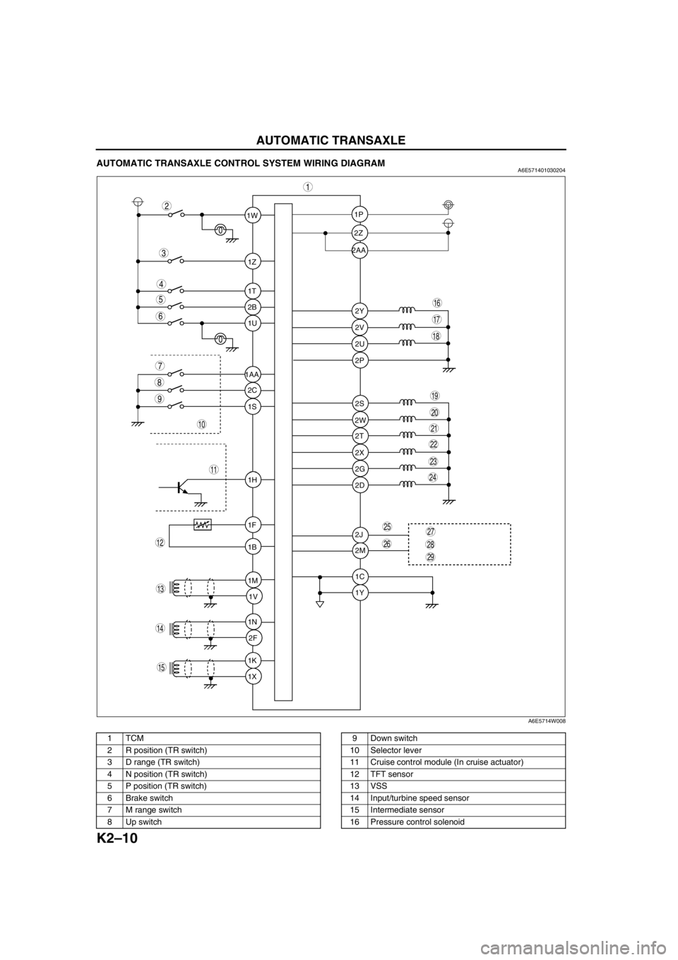
AUTOMATIC TRANSAXLE CONTROL SYSTEM WIRING DIAGRAMA6E571401030204
.
1W1P
2P
2S
2T
2X
2G
2D
2J
2M
1C
1Y 2W 2Z
2Y
2V
2U 1Z
1T
2B
1U
2C
1S
1H
1F
1B
1M
1V
1N
2F
1K
1X 1AA2AA
9
8
7
5
4
3
1
2
10
19
18
17
15
16
14
13
11
12
20
6
29
28
2725
26
24
23
21
22
A6E5714W008
1TCM
2 R position (TR switch)
3 D range (TR switch)
4 N position (TR switch)
5 P position (TR switch)
6 Brake switch
7 M range switch
8 Up switch9 Down switch
10 Selector lever
11 Cruise control module (In cruise actuator)
12 TFT sensor
13 VSS
14 Input/turbine speed sensor
15 Intermediate sensor
16 Pressure control solenoid
Page 465 of 909

K2–50
AUTOMATIC TRANSAXLE
CONTROLLER AREA NETWORK (CAN) DESCRIPTIONA6E571418901201Outline
•The TCM transmits/receives information using the CAN system. See Section T for detailed information
regarding the CAN system.
Structure/Operation
•The PCM inputs throttle opening angle, engine speed, engine torque, engine coolant temperature. to the TCM.
•The TCM operates shift and TCC controls based on the throttle opening angle, and controls line pressure and
other based on the throttle opening angle and the engine torque.
•The TCM outputs reduce torque signal, range signal, turbine speed, ATF temperature signal, and TCC signal to
the PCM.
•If there is an open or short circuit in the CAN wiring, the system determines that the CAN is abnormal and
switches to fail-safe mode.
Input
•Throttle position
•Engine torque (without torque down)
•Engine torque (with torque down)
•Engine torque (loss torque)
•Torque reduction request
•ECT
•Engine speed
•Buttery reconnection
Output
•Range position
•Turbine speed
•ATF temperature
•TCC
•Racing select
•Gear position
•Desired torque
•Desired gear position
•Upper torque limit
•Traveled distance
•MIL indicate request
•AT warning light indicate request
End Of Sie
Page 543 of 909
K2–128
ON-BOARD DIAGNOSTIC
End Of Sie
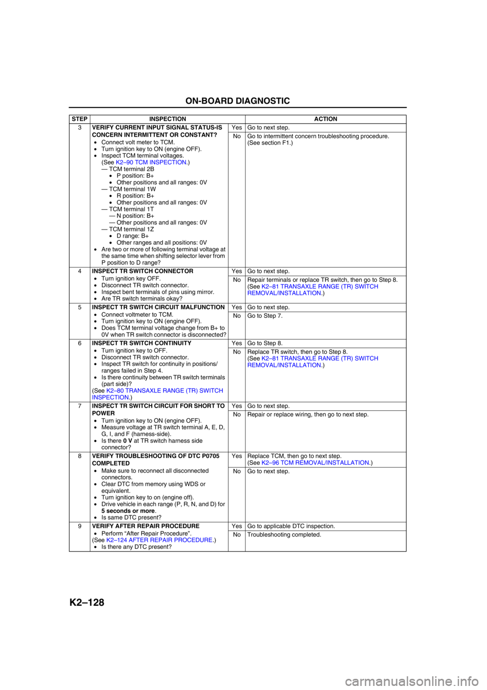
3VERIFY CURRENT INPUT SIGNAL STATUS-IS
CONCERN INTERMITTENT OR CONSTANT?
•Connect volt meter to TCM.
•Turn ignition key to ON (engine OFF).
•Inspect TCM terminal voltages.
(See K2–90 TCM INSPECTION.)
—TCM terminal 2B
•P position: B+
•Other positions and all ranges: 0V
—TCM terminal 1W
•R position: B+
•Other positions and all ranges: 0V
—TCM terminal 1T
—N position: B+
—Other positions and all ranges: 0V
—TCM terminal 1Z
•D range: B+
•Other ranges and all positions: 0V
•Are two or more of following terminal voltage at
the same time when shifting selector lever from
P position to D range?Yes Go to next step.
No Go to intermittent concern troubleshooting procedure.
(See section F1.)
4INSPECT TR SWITCH CONNECTOR
•Turn ignition key OFF.
•Disconnect TR switch connector.
•Inspect bent terminals of pins using mirror.
•Are TR switch terminals okay?Yes Go to next step.
No Repair terminals or replace TR switch, then go to Step 8.
(See K2–81 TRANSAXLE RANGE (TR) SWITCH
REMOVAL/INSTALLATION.)
5INSPECT TR SWITCH CIRCUIT MALFUNCTION
•Connect voltmeter to TCM.
•Turn ignition key to ON (engine OFF).
•Does TCM terminal voltage change from B+ to
0V when TR switch connector is disconnected?Yes Go to next step.
No Go to Step 7.
6INSPECT TR SWITCH CONTINUITY
•Turn ignition key to OFF.
•Disconnect TR switch connector.
•Inspect TR switch for continuity in positions/
ranges failed in Step 4.
•Is there continuity between TR switch terminals
(part side)?
(See K2–80 TRANSAXLE RANGE (TR) SWITCH
INSPECTION.)Yes Go to Step 8.
No Replace TR switch, then go to Step 8.
(See K2–81 TRANSAXLE RANGE (TR) SWITCH
REMOVAL/INSTALLATION.)
7INSPECT TR SWITCH CIRCUIT FOR SHORT TO
POWER
•Turn ignition key to ON (engine OFF).
•Measure voltage at TR switch terminal A, E, D,
G, I, and F (harness-side).
•Is there 0 V at TR switch harness side
connector?Yes Go to next step.
No Repair or replace wiring, then go to next step.
8VERIFY TROUBLESHOOTING OF DTC P0705
COMPLETED
•Make sure to reconnect all disconnected
connectors.
•Clear DTC from memory using WDS or
equivalent.
•Turn ignition key to on (engine off).
•Drive vehicle in each range (P, R, N, and D) for
5 seconds or more.
•Is same DTC present?Yes Replace TCM, then go to next step.
(See K2–96 TCM REMOVAL/INSTALLATION.)
No Go to next step.
9VERIFY AFTER REPAIR PROCEDURE
•Perform “After Repair Procedure”.
(See K2–124 AFTER REPAIR PROCEDURE.)
•Is there any DTC present?Yes Go to applicable DTC inspection.
No Troubleshooting completed. STEP INSPECTION ACTION
Page 545 of 909
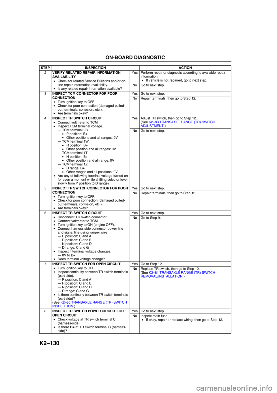
K2–130
ON-BOARD DIAGNOSTIC
2VERIFY RELATED REPAIR INFORMATION
AVAILABILITY
•Check for related Service Bulletins and/or on-
line repair information availability.
•Is any related repair information available?Yes Perform repair or diagnosis according to available repair
information.
•If vehicle is not repaired, go to next step.
No Go to next step.
3INSPECT TCM CONNECTOR FOR POOR
CONNECTION
•Turn ignition key to OFF.
•Check for poor connection (damaged pulled-
out terminals, corrosion, etc.).
•Are terminals okay?Yes Go to next step.
No Repair terminals, then go to Step 12.
4INSPECT TR SWITCH CIRCUIT
•Connect voltmeter to TCM.
•Inspect TCM terminal voltage.
—TCM terminal 2B
•P position: B+
•Other positions and all ranges: 0V
—TCM terminal 1W
•R position: B+
•Other position and all ranges: 0V
—TCM terminal 1T
•N position: B+
•Other position and all range: 0V
—TCM terminal 1Z
•D range: B+
•Other ranges and all positions: 0V
•Are any of following terminal voltage turned on
for even a moment while shifting selector lever
slowly from P position to D range?Yes Adjust TR switch, then go to Step 12.
(See K2–83 TRANSAXLE RANGE (TR) SWITCH
ADJUSTMENT.)
No Go to next step.
5INSPECT TR SWITCH CONNECTOR FOR POOR
CONNECTION
•Turn ignition key to OFF.
•Check for poor connection (damaged pulled-
out terminals, corrosion, etc.).
•Are terminals okay?Yes Go to next step.
No Repair terminals, then go to Step 12.
6INSPECT TR SWITCH CIRCUIT
•Disconnect TR switch connector.
•Connect voltmeter to TCM.
•Turn ignition key to ON (engine OFF).
•Connect harness side connector power line
and signal line using jumper wire
—P position: C and A
—R position: C and E
—N position: C and D
—D range: C and G
•Inspect if terminal voltage changes.
—0V to B+
•Does terminal voltage change?Yes Go to next step.
No Go to Step 9.
7INSPECT TR SWITCH FOR OPEN CIRCUIT
•Turn ignition key to OFF.
•Inspect continuity between TR switch terminals
(part side).
—P position: C and A
—R position: C and E
—N position: C and D
—D range: C and G
•Is there continuity between TR switch terminals
(part side)?
(See K2–80 TRANSAXLE RANGE (TR) SWITCH
INSPECTION.)Yes Go to Step 12.
No Replace TR switch, then go to Step 12.
(See K2–81 TRANSAXLE RANGE (TR) SWITCH
REMOVAL/INSTALLATION.)
8INSPECT TR SWITCH POWER CIRCUIT FOR
OPEN CIRCUIT
•Check voltage at TR switch terminal C
(harness-side).
•Is there B+ at TR switch terminal C (harness-
side)?Yes Go to next step.
No Inspect main fuse.
•If okay, repair or replace wiring, then go to Step 12. STEP INSPECTION ACTION
Page 604 of 909

TROUBLESHOOTING
K2–189
K2
Diagnostic procedure
End Of SieNO.3 VEHICLE MOVES IN P POSITION, OR PARKING GEAR DOES NOT DISENGAGE WHEN P IS
DISENGAGED
A6E578001030206
End Of SieNO.4 EXCESSIVE CREEPA6E578001030207
End Of SieNO.5 NO CREEP AT ALLA6E578001030208
STEP INSPECTION ACTION
1•Does vehicle creep when selector lever
moved slightly in N position?Yes•Overhaul control valve body and repair or replace any
defective parts.
(See ATX Workshop Manual.)
—If problem remains, replace or overhaul transaxle and
repair or replace any defective parts.
(See K2–99 AUTOMATIC TRANSAXLE AND
TRANSFER REMOVAL/INSTALLATION.)
(See ATX Workshop Manual.)
No Inspect and adjust selector lever.
(See K2–117 SELECTOR LEVER INSPECTION.)
(See K2–118 SELECTOR CABLE ADJUSTMENT.)
2•Verify test results.
—If okay, return to diagnostic index to service any additional symptoms.
—If malfunction remains, inspect related Service Informations and perform repair or diagnosis.
—If vehicle repaired, troubleshooting completed.
—If vehicle not repaired or additional diagnostic information not available, replace TCM.
3 Vehicle moves in P position, or parking gear does not disengage when P is disengaged
DESCRIPTION•Vehicle rolls when on a downward slope and tires do not lock in P position.
•Tires locked when P disengaged, vehicle does not move in D range, and R position when accelerator
pedal depressed, and engine remains in stall condition.
POSSIBLE
CAUSE•Malfunction of parking mechanism (May have effect on noise or shock from transaxle)
•Improper adjustment of selector lever
•If vehicle moves in N position, perform symptom troubleshooting No.2 “Vehicle moves in N position”
Note
•Before following troubleshooting steps, make sure that Automatic Transaxle On-Board Diagnostic
and Automatic Transaxle Basic Inspection are conducted.
4 Excessive creep
DESCRIPTION•Vehicle accelerates in D range, and R position without depressing accelerator pedal.
POSSIBLE
CAUSE•Engine idle speed high (transaxle system is not cause of problem)
•Go to symptom troubleshooting No.9 “Fast idle/runs on”
(See Section F.)
Note
•Before following troubleshooting steps, make sure that Automatic Transaxle On-Board Diagnostic
and Automatic Transaxle Basic Inspection are conducted.
5 No creep at all
DESCRIPTION•Vehicle does not move in D range, or R position when idling on flat paved road.
POSSIBLE
CAUSE•Either engine output low or there is clutch circuit slippage.
—Clutch burned
•Line pressure low
•Malfunction of shift solenoid A, B, or C
•Malfunction of body ground
•Malfunction of control valve body
—Transaxle fixed in 4GR (Operation of fail-safe function)
•Short or open circuit in wiring
•Poor connection of connector
•Electronic parts of output and input system malfunctioning
—Engine torque is not start
•Malfunction of torque converter
Note
•Before following troubleshooting steps, make sure that Automatic Transaxle On-Board Diagnostic
and Automatic Transaxle Basic Inspection are conducted.