alternator MAZDA 6 2002 Workshop Manual Suplement
[x] Cancel search | Manufacturer: MAZDA, Model Year: 2002, Model line: 6, Model: MAZDA 6 2002Pages: 909, PDF Size: 17.16 MB
Page 8 of 909

NEW STANDARDS
GI–5
GINEW STANDARDS TABLEA6E202800020201•The following is a comparison of the previous standard and the new standard.
NEW STANDARDS
New Standard Previous Standard
Remark
Abbrevi-
ationNameAbbrevi-
ationName
AP Accelerator Pedal—Accelerator Pedal
ACL Air Cleaner—Air Cleaner
A/C Air Conditioning—Air Conditioning
BARO Barometric Pressure—Atmospheric Pressure
B+ Battery Positive VoltageV
BBattery Voltage
—Brake Switch—Stoplight Switch
—Calibration Resistor—Corrected Resistance #6
CMP sensor Camshaft Position Sensor—Crank Angle Sensor
CAC Charge Air Cooler—Intercooler
CLS Closed Loop System—Feedback System
CTP Closed Throttle Position—Fully Closed
—Closed Throttle Position Switch—Idle Switch
CPP Clutch Pedal Position—Clutch Position
CIS Continuous Fuel Injection System EGI Electronic Gasoline Injection System
CS sensor Control Sleeve Sensor CSP sensor Control Sleeve Position Sensor #6
CKP sensor Crankshaft Position Sensor—Crank Angle Sensor 2
DLC Data Link Connector—Diagnosis Connector
DTM Diagnostic Test Mode—Test Mode #1
DTC Diagnostic Trouble Code—Service Code(s)
DI Distributor Ignition—Spark Ignition
DLI Distributorless Ignition—Direct Ignition
EI Electronic Ignition—Electronic Spark Ignition #2
ECT Engine Coolant Temperature—Water Thermo
EM Engine Modification—Engine Modification
—Engine Speed Input Signal—Engine RPM Signal
EVAP Evaporative Emission—Evaporative Emission
EGR Exhaust Gas Recirculation—Exhaust Gas Recirculation
FC Fan Control—Fan Control
FF Flexible Fuel—Flexible Fuel
4GR Fourth Gear—Overdrive
—Fuel Pump Relay—Circuit Opening Relay #3
FSO
solenoidFuel Shut Off Solenoid FCV Fuel Cut Valve #6
GEN Generator—Alternator
GND Ground—Ground/Earth
HO2S Heated Oxygen Sensor—Oxygen Sensor With heater
IAC Idle Air Control—Idle Speed Control
—IDM Relay—Spill Valve Relay #6
—Incorrect Gear Ratio——
—Injection Pump FIP Fuel Injection Pump #6
—Input/Turbine Speed Sensor—Pulse Generator
IAT Intake Air Temperature—Intake Air Thermo
KS Knock Sensor—Knock Sensor
MIL Malfunction Indicator Lamp—Malfunction Indicator Light
MAP Manifold Absolute Pressure—Intake Air Pressure
MAF sensor Mass Air Flow Sensor—Airflow Sensor
MFI Multiport Fuel Injection—Multiport Fuel Injection
OBD On Board Diagnostic—Diagnosis/Self Diagnosis
Page 744 of 909

CONVENTIONAL BRAKE SYSTEM
P–11
P
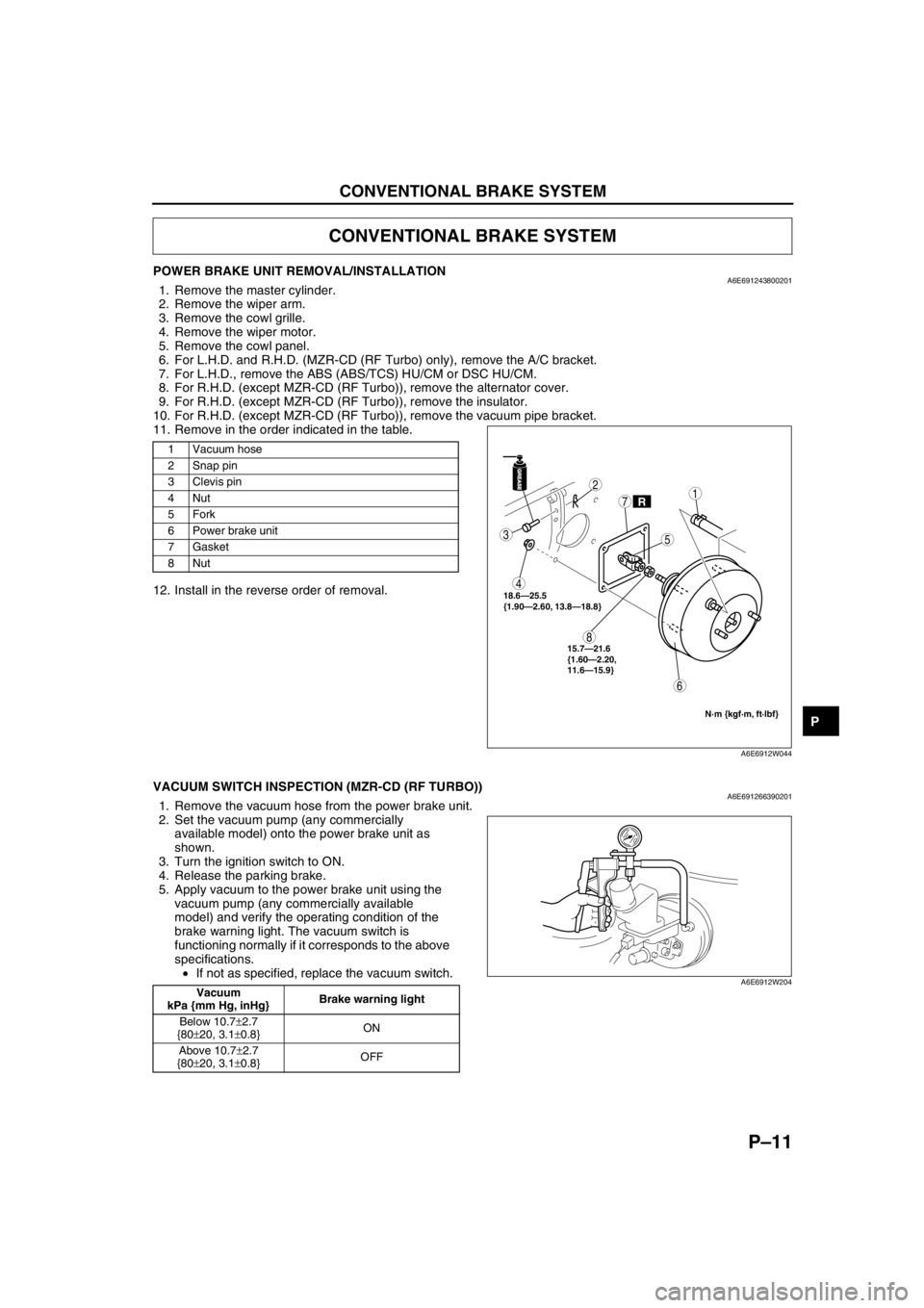
POWER BRAKE UNIT REMOVAL/INSTALLATIONA6E6912438002011. Remove the master cylinder.
2. Remove the wiper arm.
3. Remove the cowl grille.
4. Remove the wiper motor.
5. Remove the cowl panel.
6. For L.H.D. and R.H.D. (MZR-CD (RF Turbo) only), remove the A/C bracket.
7. For L.H.D., remove the ABS (ABS/TCS) HU/CM or DSC HU/CM.
8. For R.H.D. (except MZR-CD (RF Turbo)), remove the alternator cover.
9. For R.H.D. (except MZR-CD (RF Turbo)), remove the insulator.
10. For R.H.D. (except MZR-CD (RF Turbo)), remove the vacuum pipe bracket.
11. Remove in the order indicated in the table.
12. Install in the reverse order of removal.
End Of Sie
VACUUM SWITCH INSPECTION (MZR-CD (RF TURBO))A6E6912663902011. Remove the vacuum hose from the power brake unit.
2. Set the vacuum pump (any commercially
available model) onto the power brake unit as
shown.
3. Turn the ignition switch to ON.
4. Release the parking brake.
5. Apply vacuum to the power brake unit using the
vacuum pump (any commercially available
model) and verify the operating condition of the
brake warning light. The vacuum switch is
functioning normally if it corresponds to the above
specifications.
•If not as specified, replace the vacuum switch.
End Of Sie
CONVENTIONAL BRAKE SYSTEM
1 Vacuum hose
2 Snap pin
3Clevis pin
4Nut
5Fork
6 Power brake unit
7Gasket
8Nut
GREASEGREASE
R
3
4
8
6
2
7
5
1
18.6—25.5
{1.90—2.60, 13.8—18.8}
N·m {kgf·m, ft·lbf}
15.7—21.6
{1.60—2.20,
11.6—15.9}
A6E6912W044
Vacuum
kPa {mm Hg, inHg}Brake warning light
Below 10.7±2.7
{80±20, 3.1±0.8}ON
Above 10.7±2.7
{80±20, 3.1±0.8}OFFA6E6912W204