ECO mode MAZDA 6 2002 Workshop Manual Suplement
[x] Cancel search | Manufacturer: MAZDA, Model Year: 2002, Model line: 6, Model: MAZDA 6 2002Pages: 909, PDF Size: 17.16 MB
Page 7 of 909

GI–4
FUNDAMENTAL PROCEDURES
DYNAMOMETERA6E2014000042174WD testing/servicing
•Brake tester
Caution
•
To ensure the stability of the drag force of the viscous coupling always perform a brake test after
using the dynamometer or speed meter tester.
Note
•If there is a great amount of brake drag, it is probably due to the viscosity of the viscous coupling or the
center differential (RBC). To remove the influence of the coupling, jack up all four wheels of the vehicle
and verify that each wheel can be rotated freely by hand.
•Chassis dynamometer/speed meter tester
Caution
•
The vehicle may sway or surge forward when on the dynamometer. To prevent possible vehicle
movement, firmly secure it in place using steel retainers (chain, wire or similar) attached to the
front and rear towing hooks or to the tie down hooks.
•
Do not pop the clutch.
•
Do not accelerate suddenly.
Note
•The dynamometer/speed meter tester has two setting modes: propeller shaft removed mode and free
roller mode. After placing the vehicle on the tester and setting the wheels on the free rollers, start the
engine. For MTX vehicles, set the shift lever into second gear and gently, at low idle speed, release the
clutch pedal. For ATX vehicles, set the selector lever to D range, and slowly accelerate.
End Of Sie
FUNDAMENTAL PROCEDURES
Page 9 of 909

GI–6
NEW STANDARDS
#1 : Diagnostic trouble codes depend on the diagnostic test mode.
#2 : Controlled by the PCM
#3 : In some models, there is a fuel pump relay that controls pump speed. That relay is now called the fuel pump
relay (speed).
#4 : Device that controls engine and powertrain
#5 : Directly connected to exhaust manifold
#6 : Part name of diesel engine
End Of Sie
OL Open Loop—Open Loop
—Output Speed Sensor—Vehicle Speed Sensor 1
OC Oxidation Catalytic Converter—Catalytic Converter
O2S Oxygen Sensor—Oxygen Sensor
PNP Park/Neutral Position—Park/Neutral Range
—PCM Control Relay—Main Relay #6
PSP Power Steering Pressure—Power Steering Pressure
PCM Powertrain Control Module ECU Engine Control Unit #4
—Pressure Control Solenoid—Line Pressure Solenoid Valve
PAIR Pulsed Secondary Air Injection—Secondary Air Injection SystemPulsed
injection
—Pump Speed Sensor—NE Sensor #6
AIR Secondary Air Injection—Secondary Air Injection SystemInjection
with air
pump
SAPV Secondary Air Pulse Valve—Reed Valve
SFI Sequential Multiport Fuel Injection—Sequential Fuel Injection
—Shift Solenoid A—1–2 Shift Solenoid Valve
—Shift A Solenoid Valve
—Shift Solenoid B—2–3 Shift Solenoid Valve
—Shift B Solenoid Valve
—Shift Solenoid C—3–4 Shift Solenoid Valve
3GR Third Gear—3rd Gear
TWC Three Way Catalytic Converter—Catalytic Converter
TB Throttle Body—Throttle Body
TP sensor Throttle Position Sensor—Throttle Sensor
TCV Timer Control Valve TCV Timing Control Valve #6
TCC Torque Converter Clutch—Lockup Position
TCMTransmission (Transaxle) Control
Module—EC-AT Control Unit
—Transmission (Transaxle) Fluid
Temperature Sensor—ATF Thermosensor
TR Transmission (Transaxle) Range—Inhibitor Position
TC Turbocharger—Turbocharger
VSS Vehicle Speed Sensor—Vehicle Speed Sensor
VR Voltage Regulator—IC Regulator
VAF sensor Volume Air Flow Sensor —Airflow Meter
WU-TWCWarm Up Three Way Catalytic
Converter—Catalytic Converter #5
WOT Wide Open Throttle—Fully Open New Standard Previous Standard
Remark
Abbrevi-
ationNameAbbrevi-
ationName
Page 66 of 909

D–2
OUTLINE
OUTLINE OF CONSTRUCTIONA6E330202000201•The construction and the operation of the oil cooler and the oil filter for the new Mazda6 (GG, GY) MZR-CD (RF
Turbo) engine model is the same as the current Mazda MPV (LW) MZR-CD (RF Turbo) engine model. (See
Mazda MPV Workshop Manual Supplement 1737-1*-02D.)
•The construction and the operation of the lubrication system except for the oil cooler and oil filter for the new
Mazda6 (GG, GY) MZR-CD (RF Turbo) engine model is the same as the current Mazda 626, 626 Station
Wagon (GF, GW) RF Turbo engine model. (European specs.) (See Mazda 626, 626 Station Wagon RF Turbo
Workshop Manual Supplement 1614-10-98D.)
•The construction and the operation of the lubrication system for the new Mazda6 (GG, GY) L8, LF, and L3
engine models is the same as the current Mazda6 (GG) engine model L8, LF, and L3 engine models. (See
Mazda6 Training Manual 3359-1*-02C, Mazda6 Workshop Manual 1730-1*-02C.)
End Of Sie
SPECIFICATIONSA6E330202000202Gasoline engine
* : Always verify the oil level with the dipsticks since the engine oil capacity differs according to dipstick
specifications. (See Mazda6 Workshop Manual 1730-1*-02C Section D.)
Recommended Engine Oil (Gasoline Engine)
•The maintenance intervals on the scheduled maintenance table (See GI–8 SCHEDULED MAINTENANCE
TABLE) can only be supported with the use of following oils.
OUTLINE
ItemSpecification
New
Mazda6
(GG, GY)Current
Mazda6
(GG)New
Mazda6
(GG, GY)Current
Mazda6
(GG)New
Mazda6
(GG, GY)Current
Mazda6
(GG)
L8 LF L3*
Lubrication system Force-fed type
Oil coolerWater-cooled
Oil pressure
(approximate quantity)
[oil temperature: 100°C
{212°F}](kPa {kgf/cm
2, psi})
min [rpm]234—521
{2.39—5.31, 33.9—75.5}
[3,000]395—649
{4.03—6.61,
57.3—94.1}
[3,000]
Oil pumpType Trochoid gear type
Relief pressure
(approximate
quantity) (kPa {kgf/cm
2,
psi})500—600
{5.09—6.11, 72.6—87.0}
Oil filterType Full-flow, Paper element
Bypass pressure
(approximate
quantity)(kPa kgf/cm
2, psi})80—120
{0.9—1.2, 12.8—17.0}
Oil capacity
(approximate
quantity)Total
(dry engine)(L {US qt, lmp qt}) 4.6 {4.8, 4.0} Dipstick A: 4.2 {4.4, 3.7}
Dipstick B: 5.1 {5.4, 4.5}
Oil replacement (L {US qt, lmp qt}) 3.9 {4.0, 3.4} Dipstick A: 3.1 {3.3, 2.7}
Dipstick B: 4.0 {4.2, 3.5}
Oil and oil filter
replacement(L {US qt, lmp qt}) 4.3 {4.5, 3.8} Dipstick A: 3.5 {3.7, 3.1}
Dipstick B: 4.4 {4.6, 3.9}
ItemSpecification
New Mazda6
(GG, GY), Current Mazda6
(GG)New Mazda6
(GG, GY), Current Mazda6
(GG)
L8, LF, L3
Engine oil GradeAPI SL
ACEA A3
Viscosity (SAE) 5W-30, 10W-40 5W-20
RemarksMazda genuine Dexelia oil e.g. —
Page 89 of 909
![MAZDA 6 2002 Workshop Manual Suplement F1–1
F1
F1FUEL AND EMISSION CONTROL SYSTEM
[L8, LF, L3]
OUTLINE.............................................................. F1-2
OUTLINE OF CONSTRUCTION ....................... F1-2
FEATURES ..... MAZDA 6 2002 Workshop Manual Suplement F1–1
F1
F1FUEL AND EMISSION CONTROL SYSTEM
[L8, LF, L3]
OUTLINE.............................................................. F1-2
OUTLINE OF CONSTRUCTION ....................... F1-2
FEATURES .....](/img/28/57057/w960_57057-88.png)
F1–1
F1
F1FUEL AND EMISSION CONTROL SYSTEM
[L8, LF, L3]
OUTLINE.............................................................. F1-2
OUTLINE OF CONSTRUCTION ....................... F1-2
FEATURES ........................................................ F1-2
SPECIFICATIONS ............................................. F1-2
CONTROL SYSTEM DIAGRAM (4WD)............. F1-3
CONTROL SYSTEM WIRING DIAGRAM
(4WD).............................................................. F1-4
FUEL SYSTEM..................................................... F1-9
OUTLINE ........................................................... F1-9
STRUCTURAL VIEW......................................... F1-9
SYSTEM DIAGRAM ........................................ F1-10
FUEL PUMP (TRANSFER).............................. F1-10
QUICK RELEASE CONNECTOR (FUEL TANK
SIDE, TRANSFER HOSE PART) ................. F1-12
EXHAUST SYSTEM........................................... F1-13
OUTLINE ......................................................... F1-13
STRUCTURAL VIEW....................................... F1-13
CONTROL SYSTEM........................................... F1-14
OUTLINE ......................................................... F1-14
STRUCTURAL VIEW (4WD) ........................... F1-16
BLOCK DIAGRAM ........................................... F1-17
CONTROL DEVICE AND CONTROL
RELATIONSHIP CHART .............................. F1-19
CONTROLLER AREA NETWORK (CAN) ....... F1-21
OUTLINE............................................................ F1-22
SUPPLEMENTAL SERVICE
INFORMATION ............................................. F1-22
ENGINE TUNE-UP............................................. F1-22
IDLE SPEED INSPECTION (4WD) ................. F1-22
FUEL SYSTEM................................................... F1-23
FUEL TANK REMOVAL/INSTALLATION ........ F1-23
FUEL PUMP UNIT
REMOVAL/INSTALLATION .......................... F1-26
FUEL HOSE (FUEL TANK SIDE,
TRANSFER HOSE PART)
REMOVAL/INSTALLATION .......................... F1-29
EXHAUST SYSTEM........................................... F1-30
EXHAUST SYSTEM
REMOVAL/INSTALLATION .......................... F1-30
CONTROL SYSTEM........................................... F1-33
PCM INSPECTION (4WD)............................... F1-33
ON-BOARD DIAGNOSTIC................................. F1-50
OUTLINE ......................................................... F1-50
CONTROL DEVICE AND MONITORING
SYSTEM RELATIONSHIP CHART .............. F1-50
DIAGNOSTIC TEST MODE (4WD) ................. F1-50
DTC (4WD) ...................................................... F1-52
OBD DRIVE MODE ......................................... F1-52
DTC TABLE ..................................................... F1-54
TROUBLESHOOTING........................................ F1-57ENGINE SYMPTOM
TROUBLESHOOTING .................................. F1-57
QUICK DIAGNOSTIC CHART ......................... F1-58
NO.14 POOR FUEL ECONOMY ..................... F1-62
NO.22 VIBRATION CONCERNS
(ENGINE) ...................................................... F1-64 FEATURES
SERVICE
Page 109 of 909

CONTROL SYSTEM
F1–21
F1
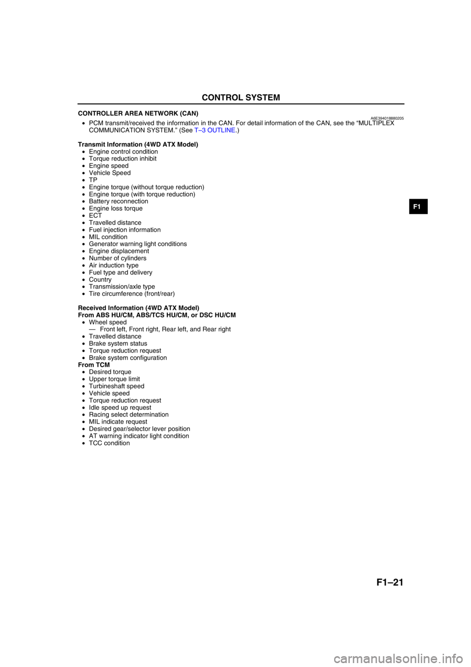
CONTROLLER AREA NETWORK (CAN)A6E394018880205•PCM transmit/received the information in the CAN. For detail information of the CAN, see the “MULTIPLEX
COMMUNICATION SYSTEM.” (See T–3 OUTLINE.)
Transmit Information (4WD ATX Model)
•Engine control condition
•Torque reduction inhibit
•Engine speed
•Vehicle Speed
•TP
•Engine torque (without torque reduction)
•Engine torque (with torque reduction)
•Battery reconnection
•Engine loss torque
•ECT
•Travelled distance
•Fuel injection information
•MIL condition
•Generator warning light conditions
•Engine displacement
•Number of cylinders
•Air induction type
•Fuel type and delivery
•Country
•Transmission/axle type
•Tire circumference (front/rear)
Received Information (4WD ATX Model)
From ABS HU/CM, ABS/TCS HU/CM, or DSC HU/CM
•Wheel speed
—Front left, Front right, Rear left, and Rear right
•Travelled distance
•Brake system status
•Torque reduction request
•Brake system configuration
From TCM
•Desired torque
•Upper torque limit
•Turbineshaft speed
•Vehicle speed
•Torque reduction request
•Idle speed up request
•Racing select determination
•MIL indicate request
•Desired gear/selector lever position
•AT warning indicator light condition
•TCC condition
End Of Sie
Page 140 of 909

F1–52
ON-BOARD DIAGNOSTIC
End Of Sie
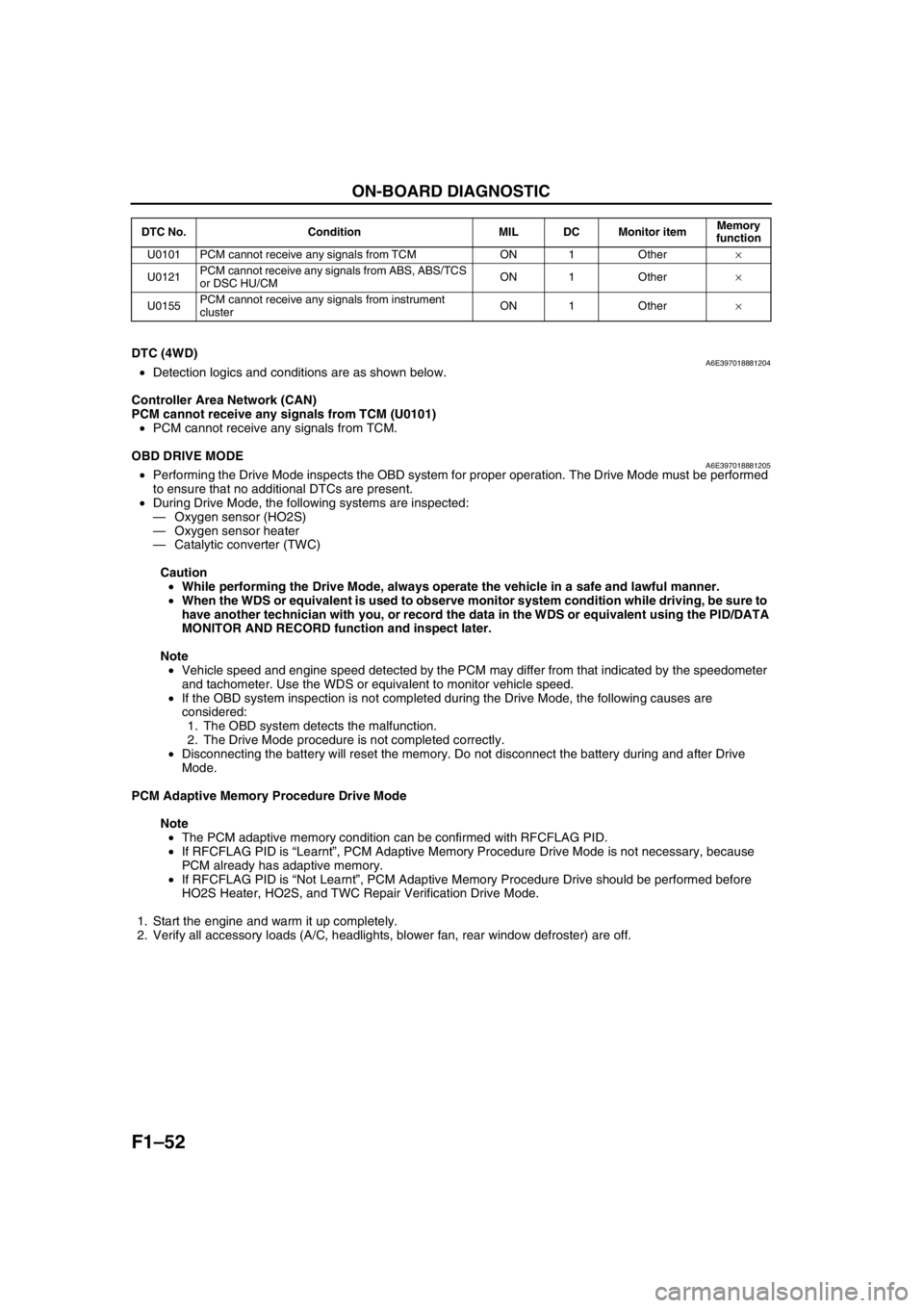
DTC (4WD)A6E397018881204•Detection logics and conditions are as shown below.
Controller Area Network (CAN)
PCM cannot receive any signals from TCM (U0101)
•PCM cannot receive any signals from TCM.
End Of Sie
OBD DRIVE MODEA6E397018881205•Performing the Drive Mode inspects the OBD system for proper operation. The Drive Mode must be performed
to ensure that no additional DTCs are present.
•During Drive Mode, the following systems are inspected:
—Oxygen sensor (HO2S)
—Oxygen sensor heater
—Catalytic converter (TWC)
Caution
•While performing the Drive Mode, always operate the vehicle in a safe and lawful manner.
•When the WDS or equivalent is used to observe monitor system condition while driving, be sure to
have another technician with you, or record the data in the WDS or equivalent using the PID/DATA
MONITOR AND RECORD function and inspect later.
Note
•Vehicle speed and engine speed detected by the PCM may differ from that indicated by the speedometer
and tachometer. Use the WDS or equivalent to monitor vehicle speed.
•If the OBD system inspection is not completed during the Drive Mode, the following causes are
considered:
1. The OBD system detects the malfunction.
2. The Drive Mode procedure is not completed correctly.
•Disconnecting the battery will reset the memory. Do not disconnect the battery during and after Drive
Mode.
PCM Adaptive Memory Procedure Drive Mode
Note
•The PCM adaptive memory condition can be confirmed with RFCFLAG PID.
•If RFCFLAG PID is “Learnt”, PCM Adaptive Memory Procedure Drive Mode is not necessary, because
PCM already has adaptive memory.
•If RFCFLAG PID is “Not Learnt”, PCM Adaptive Memory Procedure Drive should be performed before
HO2S Heater, HO2S, and TWC Repair Verification Drive Mode.
1. Start the engine and warm it up completely.
2. Verify all accessory loads (A/C, headlights, blower fan, rear window defroster) are off.
U0101 PCM cannot receive any signals from TCM ON 1 Other×
U0121PCM cannot receive any signals from ABS, ABS/TCS
or DSC HU/CMON 1 Other×
U0155PCM cannot receive any signals from instrument
clusterON 1 Other× DTC No. Condition MIL DC Monitor itemMemory
function
Page 147 of 909

TROUBLESHOOTING
F1–59
F1
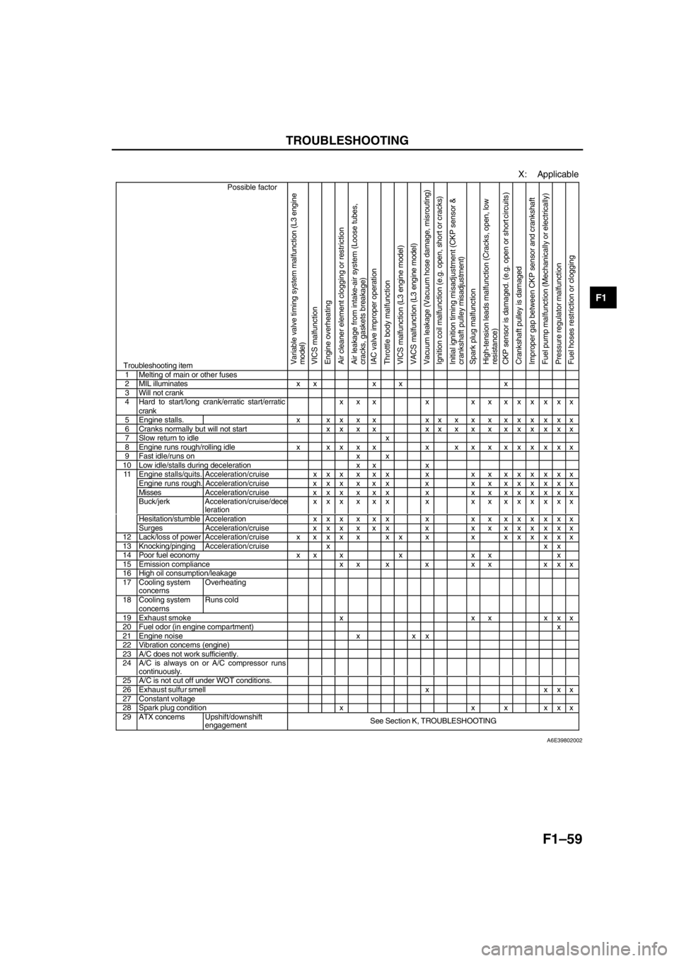
X: Applicable
Possible factor
Troubleshooting itemVariable valve timing system malfunction (L3 engine
model)
VICS malfunction
Engine overheating
Air cleaner element clogging or restriction
Air leakage from intake-air system (Loose tubes,
cracks, gaskets breakage)
IAC valve improper operation
Throttle body malfunction
VICS malfunction (L3 engine model)
VACS malfunction (L3 engine model)
Vacuum leakage (Vacuum hose damage, misrouting)
Ignition coil malfunction (e.g. open, short or cracks)
Initial ignition timing misadjustment (CKP sensor &
crankshaft pulley misadjustment)
Spark plug malfunction
High-tension leads malfunction (Cracks, open, low
resistance)
CKP sensor is damaged. (e.g. open or short circuits )
Crankshaft pulley is damaged
Improper gap between CKP sensor and crankshaft
Fuel pump malfunction (Mechanically or electrically)
Pressure regulator malfunction
Fuel hoses restriction or clogging
1 Melting of main or other fuses2 MIL illuminates x x x x x3 Will not crank4 Hard to start/long crank/erratic start/erratic
crankx x x x x x xxxxxx
5 Engine stalls. x x x x x xxxxxxxxxxx6 Cranks normally but will not start x x x x xxxxxxxxxxx7 Slow return to idle x8 Engine runs rough/rolling idle x x x x x x x x xxxxxxx9 Fast idle/runs on x x10 Low idle/stalls during deceleration x x xEngine stalls/quits. Acceleration/cruise x x x x x x x x xxxxxxxEngine runs rough. Acceleration/cruise x x x x x x x x xxxxxxxMissesAcceleration/cruise x x x x x x x x xxxxxxxBuck/jerk Acceleration/cruise/dece
lerationxxx x xx x x x xxxxxx
Hesitation/stumble Acceleration x x x x x x x x xxxxxxx
11
Surges Acceleration/cruise x x x x x x x x xxxxxxx
12 Lack/loss of powerAcceleration/cruise x x x x x x x x xxxxxxx13 Knocking/pingingAcceleration/cruise x x x14 Poor fuel economy x x x x x x x15 Emission compliance x x x x x x x x x16 High oil consumption/leakage17 Cooling system
concernsOverheating
18 Cooling system
concernsRuns cold
19 Exhaust smoke x x x x x x20 Fuel odor (in engine compartment)x21 Engine noise x x x22 Vibration concerns (engine)23 A/C does not work sufficiently.24 A/C is always on or A/C compressor runs
continuously.
25 A/C is not cut off under WOT conditions.26 Exhaust sulfur smell x x x x27 Constant voltage28 Spark plug condition x x x x x x29 ATX concernsUpshift/downshift
engagementSee Section K, TROUBLESHOOTING
A6E39802002
Page 148 of 909

F1–60
TROUBLESHOOTING
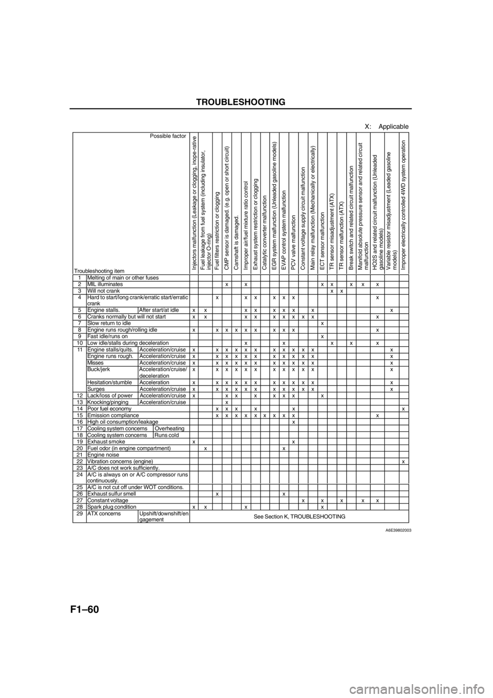
X: Applicable
Possible factor
Troubleshooting item
Injectors malfunction (Leakage or clogging, inope-rative
Fuel leakage from fuel system (including insulator,
injector O-ring)
Fuel filters restriction or clogging
CMP sensor is damaged. (e.g. open or short circuit)
Camshaft is damaged.
Improper air/fuel mixture ratio control
Exhaust system restriction or clogging
Catalytic converter malfunction
EGR system malfunction (Unleaded gasoline models)
EVAP control system malfunction
PCV valve malfunction
Constant voltage supply circuit malfunction
Main relay malfunction (Mechanically or electrically)
ECT sensor malfunction
TR sensor misadjustment (ATX)
TR sensor malfunction (ATX)
Break switch and related circuit malfunction
Manifold absolute pressure sensor and related circuit
malfunction
HO2S and related circuit malfunction (Unleaded
gasoline models)
Variable resistor misadjustment (Leaded gasoline
models)
Improper electrically controlled 4WD system operation
1 Melting of main or other fuses2 MIL illuminates x x x x x x x3 Will not crankxx4 Hard to start/long crank/erratic start/erratic
crankx xx xxx x
5 Engine stalls. After start/at idle x x x x x x x x x6 Cranks normally but will not start x x x xxxxxx x7 Slow return to idlex8 Engine runs rough/rolling idle xxxxxx xxx x9 Fast idle/runs onx10 Low idle/stalls during deceleration x x x x xEngine stalls/quits.Acceleration/cruisex xxxxx xxxxx xEngine runs rough. Acceleration/cruisex xxxxx xxxxx xMissesAcceleration/cruisex xxxxx xxxxx xBuck/jerk Acceleration/cruise/
decelerationx xxxxx xxxxx x
Hesitation/stumble Acceleration xxxxxx xxxxx x
11
Surges Acceleration/cruise xxxxxx xxxxx x
12 Lack/loss of power Acceleration/cruise x x x x x x x x13 Knocking/pingingAcceleration/cruise x14 Poor fuel economy x x x x x x15 Emission compliancexxxxxxxxx x16 High oil consumption/leakage x17 Cooling system concerns Overheating18 Cooling system concernsRuns cold19 Exhaust smoke x x20 Fuel odor (in engine compartment) x x21 Engine noise22 Vibration concerns (engine)x23 A/C does not work sufficiently.24 A/C is always on or A/C compressor runs
continuously.
25 A/C is not cut off under WOT conditions.26 Exhaust sulfur smell x x27 Constant voltage x x x x x28 Spark plug condition x x x x29 ATX concernsUpshift/downshift/en
gagementSee Section K, TROUBLESHOOTING
A6E39802003
Page 465 of 909

K2–50
AUTOMATIC TRANSAXLE
CONTROLLER AREA NETWORK (CAN) DESCRIPTIONA6E571418901201Outline
•The TCM transmits/receives information using the CAN system. See Section T for detailed information
regarding the CAN system.
Structure/Operation
•The PCM inputs throttle opening angle, engine speed, engine torque, engine coolant temperature. to the TCM.
•The TCM operates shift and TCC controls based on the throttle opening angle, and controls line pressure and
other based on the throttle opening angle and the engine torque.
•The TCM outputs reduce torque signal, range signal, turbine speed, ATF temperature signal, and TCC signal to
the PCM.
•If there is an open or short circuit in the CAN wiring, the system determines that the CAN is abnormal and
switches to fail-safe mode.
Input
•Throttle position
•Engine torque (without torque down)
•Engine torque (with torque down)
•Engine torque (loss torque)
•Torque reduction request
•ECT
•Engine speed
•Buttery reconnection
Output
•Range position
•Turbine speed
•ATF temperature
•TCC
•Racing select
•Gear position
•Desired torque
•Desired gear position
•Upper torque limit
•Traveled distance
•MIL indicate request
•AT warning light indicate request
End Of Sie
Page 480 of 909

AUTOMATIC TRANSAXLE
K2–65
K2
Memory Function
•The memory function stores failure information detected in the failure detection function. Once failure
information is stored, the memory will not be cleared even when the ignition switch is turned off (LOCK
position) or the malfunction is repaired.
•The stored memory (failure information) can be cleared by using the WDS or disconnecting the negative
battery cable.
Failure Indication Function
•The failure indication function illuminates the AT warning lights when the failure detection function determines
there is a malfunction.
DTC Table
X : Available
CCM:Continuous monitor
Fail-safe Function
•In the fail-safe function, minimum vehicle drivability is obtained by changing the signals that are determined as
malfunctions by the failure detection function to the preset values, and limiting the TCM control.
DTC No. On-board diagnostic function MILAT warning
light
indicationDCMonitor
itemMemory
function
P0705 TR switch circuit malfunction (Power short circuit) X X 2 CCM X
P0706 TR switch circuit malfunction (Open/ground short circuit) X X 2 CCM X
P0711 TFT sensor malfunction (Stuck) X–2 CCM X
P0712 TFT sensor circuit malfunction (Short circuit) X X 2 CCM X
P0713 TFT sensor circuit malfunction (Open circuit) X X 2 CCM X
P0715 Input/turbine speed sensor circuit malfunction X X 2 CCM X
P0720 Vehicle speedometer sensor circuit malfunction X X 2 CCM X
P0740 TCC system X–2 CCM X
P0743 TCC solenoid valve malfunction (Open/short) X X 1 CCM X
P0748 Pressure control solenoid malfunction (Open/short)–X–CCM X
P0751 Shift solenoid A malfunction (Stuck off) X–2 CCM X
P0752 Shift solenoid A malfunction (Stuck on) X–2 CCM X
P0753 Shift solenoid A malfunction (Open/short) X X 1 CCM X
P0756 Shift solenoid B malfunction (Stuck off) X–2 CCM X
P0757 Shift solenoid B malfunction (Stuck on) X–2 CCM X
P0758 Shift solenoid B malfunction (Open/short) X X 1 CCM X
P0761 Shift solenoid C malfunction (Stuck off) X–2 CCM X
P0762 Shift solenoid C malfunction (Stuck on) X–2 CCM X
P0763 Shift solenoid C malfunction (Open/short) X X 1 CCM X
P0768 Reduction timing solenoid malfunction (Open/short)–X–CCM X
P0773 Neutral shift solenoid malfunction (Open/short)–X–CCM X
P0778 2-4 brake solenoid malfunction (Open/short)–X–CCM X
P0791 Intermediate sensor malfunction (Open/short) X X 2 CCM X
P0798 High clutch solenoid malfunction (Open/short)–X–CCM X
P1710 GND return malfunction–––Other X
U0073 CAN BUS OFF X X 1 CCM X
U0100 TCM cannot receive any signals from PCM X X 1 CCM X
DTC
No.On-board diagnostic function Detection condition Fail-safe TCC
P0705Transaxle range (TR) switch
circuit malfunction (power short
circuit)•Two or more range signals
are inputted from TR switch
for 5 seconds or more•TR switch priority
D > N > P > R
•Inhibits feedback control,
SLOPE mode, torque
reduction controlAvailable
P0706Transaxle range (TR) switch
circuit malfunction (open/ground
short circuit)•No range signal is inputted
from TR switch for 100
seconds or more•Inhibits feedback control,
SLOPE mode, torque
reduction controlAvailable