ECO mode MAZDA 6 2002 Suplement User Guide
[x] Cancel search | Manufacturer: MAZDA, Model Year: 2002, Model line: 6, Model: MAZDA 6 2002Pages: 909, PDF Size: 17.16 MB
Page 481 of 909

K2–66
AUTOMATIC TRANSAXLE
P0711Transaxle fluid temperature (TFT)
sensor malfunction (stuck)•TFT sensor signal stays
outside normal temperature
range for 10 minute or more—Available
P0712Transaxle fluid temperature (TFT)
sensor circuit malfunction (short
circuit)•Signals form TFT sensor are
155 °C {311 °F} or greater
for 10 min.
•Inhibits feedback control
•Engine coolant temperature
signal are used for shifting.Available
P0713Transaxle fluid temperature (TFT)
sensor circuit malfunction (open
circuit)•Vehicle speed is 20 km/h
{12.4 mph} or greater, and
signals from TFT sensor are
–30 °C {–22 °F} or less for
150 seconds or moreAvailable
P0715Input/turbine speed sensor circuit
malfunction•Input/turbine speed sensor
is 600 rpm or less while
engine speed is 1500 rpm or
greater and vehicle speed is
40 km/h {24.8 mph} or
greater in D ranges.•Inhibits shift control Available
P0720Vehicle speedometer sensor
circuit malfunction•Parking gear rotation
detected by VSS is 150 rpm
or less while intermediate
sensor 1400 rpm or greater
in D range for 2 second or
more.•Inhibits SLOPE mode,
feedback control, torque
reduction controlAvailable
P0740Torque converter clutch (TCC)
system•RPM difference between
crankshaft (engine speed
signal) and reverse clutch
drum (input/turbine speed
sensor signal) exceeds the
pre-programmed value—Available
P0743Torque converter clutch (TCC)
solenoid valve malfunction (open/
short)•Open or short in torque
converter clutch solenoid
valve circuit (Voltage
different from on/off signal
relayed by CPU in TCM is
detected while TCM is
monitoring solenoid output
voltage.)•Stops driving of TCC
solenoid valve (OFF)Inhibition
P0748Pressure control solenoid
malfunction (open/short)•Open or short in pressure
control solenoid circuit
(Voltage different from on/off
signal relayed by CPU in
TCM is detected while TCM
is monitoring solenoid
output voltage.)•Stops driving of pressure
control solenoid, 2-4 brake
solenoid valve, and high
clutch solenoid valve (OFF)
•Inhibit feedback control.Available
P0751Shift solenoid A malfunction
(stuck off)•Difference between actual
gear ratio and gear ratio set
in TCM is large—Available
P0752Shift solenoid A malfunction
(stuck on)•Difference between actual
gear ratio and gear ratio set
in TCM is large—Available
P0753Shift solenoid A malfunction
(open/short)•Open or short in shift
solenoid A circuit (Voltage
different from on/off signal
relayed by CPU in TCM is
detected while TCM is
monitoring solenoid output
voltage.)•Stops driving all ON/OFF
type solenoids (OFF) and
TCC solenoid valve (OFF)Inhibition
P0756Shift solenoid B malfunction
(stuck off)•Difference between actual
gear ratio and gear ratio set
in TCM is large—Available
P0757Shift solenoid B malfunction
(stuck on)•Difference between actual
gear ratio and gear ratio set
in TCM is large—Available DTC
No.On-board diagnostic function Detection condition Fail-safe TCC
Page 490 of 909
AUTOMATIC TRANSAXLE
K2–75
K2
Time Lag Test
1. Perform mechanical system test preparation. (See K2–72 Mechanical System Test Preparation.)
2. Start the engine.
3. Warm up the engine until the ATF temperature reaches 60—70°C {140—158°F}. Shift the selector lever from N
position to D range.
4. Use a stopwatch to measure the time it takes from shifting until engagement is felt. Take three measurements
for each test and average the results using the following formula.
Formula
Average time lag = (Time 1 + Time 2 + Time 3) / 3
5. Perform the test for the following shifts in the same manner.
•N position → P position
Time lag
N → D range ... approx. 0.5—1.0 second
N → R position ... approx. 0.6— 1.0 second
Evaluation of time lag test
End Of SieROAD TESTA6E571401030210Road Test Preparation
1. Inspect the engine coolant. (See Section E.)
2. Inspect the engine oil. (See D–8 ENGINE OIL INSPECTION.)
3. Inspect the ATF levels. (See K2–78 AUTOMATIC TRANSAXLE FLUID (ATF) INSPECTION.)
4. Inspect the idle speed and ignition timing in P position. (See F1–22 IDLE SPEED INSPECTION (4WD).)
5. Bring up the engine and transaxle to normal operating temperature.
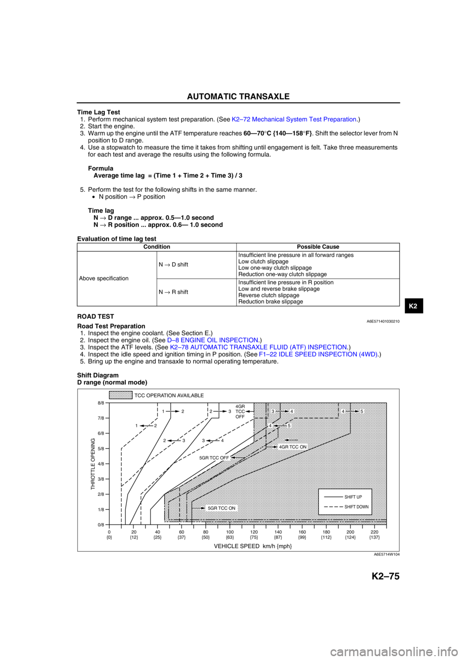
Shift Diagram
D range (normal mode)
Condition Possible Cause
Above specificationN → D shiftInsufficient line pressure in all forward ranges
Low clutch slippage
Low one-way clutch slippage
Reduction one-way clutch slippage
N → R shiftInsufficient line pressure in R position
Low and reverse brake slippage
Reverse clutch slippage
Reduction brake slippage
0/8 1/8
2/8
3/8
4/8
5/8
6/8
7/8
8/8
TCC OPERATION AVAILABLE
VEHICLE SPEED km/h {mph}
THROTTLE OPENING
SHIFT UP
4GR
TCC
OFF
SHIFT DOWN
0
{0}20
{12}40
{25}60
{37}80
{50}100
{63}120
{75}140
{87}160
{99}180
{112}220
{137} 200
{124} 112 23
2
2 232
34
4534
45
5GR TCC ON
4GR TCC ON
5GR TCC OFF
A6E5714W104
Page 741 of 909
P–8
DYNAMIC STABILITY CONTROL
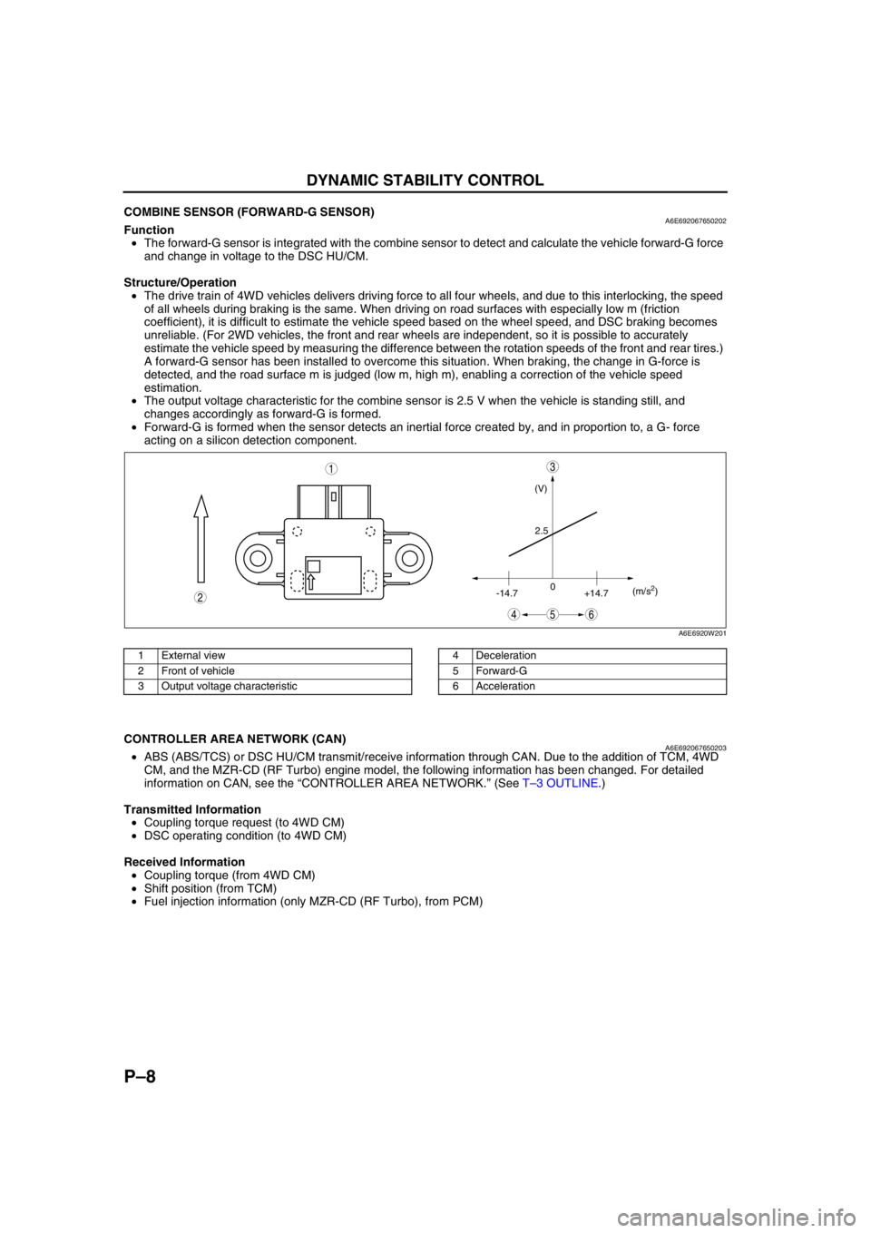
End Of SieCOMBINE SENSOR (FORWARD-G SENSOR)A6E692067650202Function
•The forward-G sensor is integrated with the combine sensor to detect and calculate the vehicle forward-G force
and change in voltage to the DSC HU/CM.
Structure/Operation
•The drive train of 4WD vehicles delivers driving force to all four wheels, and due to this interlocking, the speed
of all wheels during braking is the same. When driving on road surfaces with especially low m (friction
coefficient), it is difficult to estimate the vehicle speed based on the wheel speed, and DSC braking becomes
unreliable. (For 2WD vehicles, the front and rear wheels are independent, so it is possible to accurately
estimate the vehicle speed by measuring the difference between the rotation speeds of the front and rear tires.)
A forward-G sensor has been installed to overcome this situation. When braking, the change in G-force is
detected, and the road surface m is judged (low m, high m), enabling a correction of the vehicle speed
estimation.
•The output voltage characteristic for the combine sensor is 2.5 V when the vehicle is standing still, and
changes accordingly as forward-G is formed.
•Forward-G is formed when the sensor detects an inertial force created by, and in proportion to, a G- force
acting on a silicon detection component.
.
End Of Sie
CONTROLLER AREA NETWORK (CAN)A6E692067650203•ABS (ABS/TCS) or DSC HU/CM transmit/receive information through CAN. Due to the addition of TCM, 4WD
CM, and the MZR-CD (RF Turbo) engine model, the following information has been changed. For detailed
information on CAN, see the “CONTROLLER AREA NETWORK.” (See T–3 OUTLINE.)
Transmitted Information
•Coupling torque request (to 4WD CM)
•DSC operating condition (to 4WD CM)
Received Information
•Coupling torque (from 4WD CM)
•Shift position (from TCM)
•Fuel injection information (only MZR-CD (RF Turbo), from PCM)
End Of Sie
(V)
2.5
-14.70
+14.7(m/s
2)
45
3
6
2
1
A6E6920W201
1 External view
2 Front of vehicle
3 Output voltage characteristic4 Deceleration
5 Forward-G
6 Acceleration
Page 846 of 909
AIR BAG SYSTEM
T–35
T
CURTAIN AIR BAG MODULE REMOVAL/INSTALLATIONA6E813000171201
Warning
•Handling the air bag module improperly can accidentally deploy the air bag module, which may
seriously injure you. Read AIR BAG SYSTEM SERVICE WARNINGS before handling the air bag
module. (See T–32 SERVICE WARNINGS.)
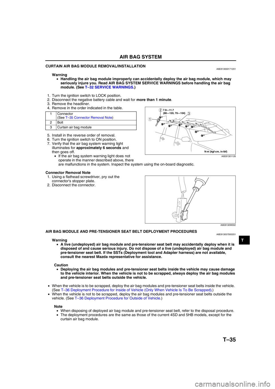
1. Turn the ignition switch to LOCK position.
2. Disconnect the negative battery cable and wait for more than 1 minute.
3. Remove the headliner.
4. Remove in the order indicated in the table.
5. Install in the reverse order of removal.
6. Turn the ignition switch to ON position.
7. Verify that the air bag system warning light
illuminates for approximately 6 seconds and
then goes off.
•If the air bag system warning light does not
operate in the manner described above, there
are malfunctions in the system. Inspect the system using the on-board diagnostic.
Connector Removal Note
1. Using a flathead screwdriver, pry out the
connector's stopper plate.
2. Disconnect the connector.
End Of SieAIR BAG MODULE AND PRE-TENSIONER SEAT BELT DEPLOYMENT PROCEDURESA6E813057000201
Warning
•A live (undeployed) air bag module and pre-tensioner seat belt may accidentally deploy when it is
disposed of and cause serious injury. Do not dispose of a live (undeployed) air bag module and
pre-tensioner seat belt. If the SSTs (Deployment tool and Adapter harness) are not available,
consult the nearest Mazda representative for assistance.
Caution
•Deploying the air bag modules and pre-tensioner seat belts inside the vehicle may cause damage
to the vehicle interior. When the vehicle is not to be scrapped, always deploy the air bag modules
and pre-tensioner seat belts outside the vehicle.
•When the vehicle is to be scrapped, deploy the air bag modules and pre-tensioner seat belts inside the vehicle.
(See T–36 Deployment Procedure for Inside of Vehicle (Only When Vehicle Is To Be Scrapped).)
•When the vehicle is not to be scrapped, deploy the air bag modules and pre-tensioner seat belts outside the
vehicle. (See T–36 Deployment Procedure for Outside of Vehicle.)
Note
•When disposing of deployed air bag module and pre-tensioner seat belt, refer to the disposal procedure.
•The deployment procedures are the same as those of the current 4SD and 5HB models, except for the
curtain air bag module.
1 Connector
(See T–35 Connector Removal Note)
2Bolt
3 Curtain air bag module3
1
2
N·m {kgf·cm, in·lbf} 7.9—11.7
{80—120, 70—104}
A6E81301126
A6E8130W002
Page 887 of 909
U–22–2
ON-BOARD DIAGNOSTIC
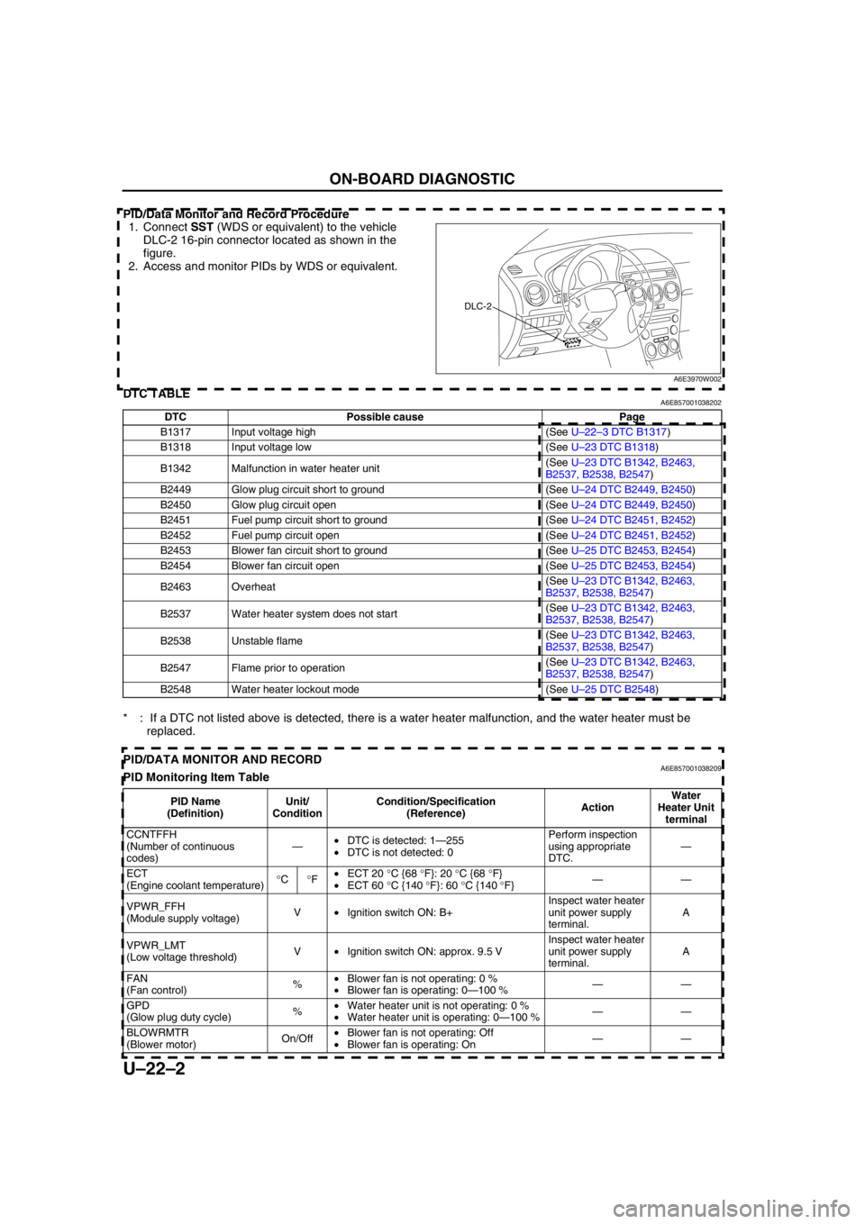
PID/Data Monitor and Record Procedure
1. Connect SST (WDS or equivalent) to the vehicle
DLC-2 16-pin connector located as shown in the
figure.
2. Access and monitor PIDs by WDS or equivalent.
End Of SieDTC TABLEA6E857001038202
* : If a DTC not listed above is detected, there is a water heater malfunction, and the water heater must be
replaced.
End Of SiePID/DATA MONITOR AND RECORDA6E857001038209PID Monitoring Item Table
DLC-2
A6E3970W002
DTC Possible cause Page
B1317 Input voltage high (See U–22–3 DTC B1317)
B1318 Input voltage low (See U–23 DTC B1318)
B1342 Malfunction in water heater unit(See U–23 DTC B1342, B2463,
B2537, B2538, B2547)
B2449 Glow plug circuit short to ground (See U–24 DTC B2449, B2450)
B2450 Glow plug circuit open (See U–24 DTC B2449, B2450)
B2451 Fuel pump circuit short to ground (See U–24 DTC B2451, B2452)
B2452 Fuel pump circuit open (See U–24 DTC B2451, B2452)
B2453 Blower fan circuit short to ground (See U–25 DTC B2453, B2454)
B2454 Blower fan circuit open (See U–25 DTC B2453, B2454)
B2463 Overheat(See U–23 DTC B1342, B2463,
B2537, B2538, B2547)
B2537 Water heater system does not start(See U–23 DTC B1342, B2463,
B2537, B2538, B2547)
B2538 Unstable flame(See U–23 DTC B1342, B2463,
B2537, B2538, B2547)
B2547 Flame prior to operation(See U–23 DTC B1342, B2463,
B2537, B2538, B2547)
B2548 Water heater lockout mode (See U–25 DTC B2548)
PID Name
(Definition)Unit/
ConditionCondition/Specification
(Reference)ActionWater
Heater Unit
terminal
CCNTFFH
(Number of continuous
codes)—•DTC is detected: 1—255
•DTC is not detected: 0Perform inspection
using appropriate
DTC.—
ECT
(Engine coolant temperature)°C°F•ECT 20 °C {68 °F}: 20 °C {68 °F}
•ECT 60 °C {140 °F}: 60 °C {140 °F}——
VPWR_FFH
(Module supply voltage)V•Ignition switch ON: B+Inspect water heater
unit power supply
terminal.A
VPWR_LMT
(Low voltage threshold)V•Ignition switch ON: approx. 9.5 VInspect water heater
unit power supply
terminal.A
FAN
(Fan control)%•Blower fan is not operating: 0 %
•Blower fan is operating: 0—100 %——
GPD
(Glow plug duty cycle)%•Water heater unit is not operating: 0 %
•Water heater unit is operating: 0—100 %——
BLOWRMTR
(Blower motor)On/Off•Blower fan is not operating: Off
•Blower fan is operating: On——
Page 888 of 909
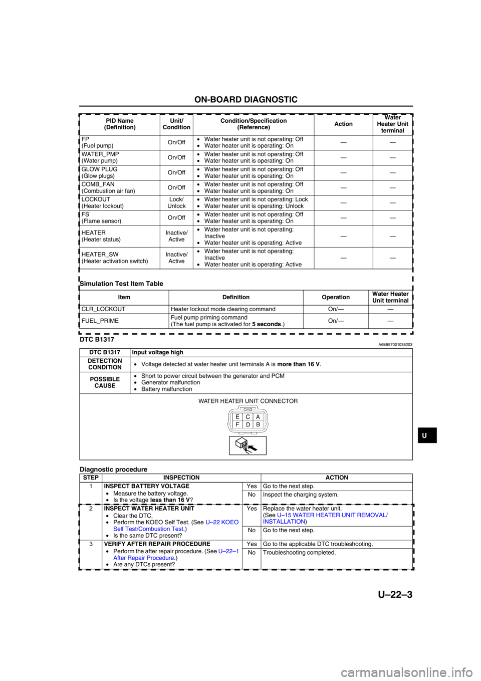
ON-BOARD DIAGNOSTIC
U–22–3
U
Simulation Test Item Table
End Of SieDTC B1317A6E857001038203
Diagnostic procedure
End Of Sie
FP
(Fuel pump)On/Off•Water heater unit is not operating: Off
•Water heater unit is operating: On——
WATER_PMP
(Water pump)On/Off•Water heater unit is not operating: Off
•Water heater unit is operating: On——
GLOW PLUG
(Glow plugs)On/Off•Water heater unit is not operating: Off
•Water heater unit is operating: On——
COMB_FAN
(Combustion air fan)On/Off•Water heater unit is not operating: Off
•Water heater unit is operating: On——
LOCKOUT
(Heater lockout)Lock/
Unlock•Water heater unit is not operating: Lock
•Water heater unit is operating: Unlock——
FS
(Flame sensor)On/Off•Water heater unit is not operating: Off
•Water heater unit is operating: On——
HEATER
(Heater status)Inactive/
Active•Water heater unit is not operating:
Inactive
•Water heater unit is operating: Active——
HEATER_SW
(Heater activation switch)Inactive/
Active•Water heater unit is not operating:
Inactive
•Water heater unit is operating: Active—— PID Name
(Definition)Unit/
ConditionCondition/Specification
(Reference)ActionWater
Heater Unit
terminal
Item Definition OperationWater Heater
Unit terminal
CLR_LOCKOUT Heater lockout mode clearing command On/——
FUEL_PRIMEFuel pump priming command
(The fuel pump is activated for 5 seconds.)On/——
DTC B1317 Input voltage high
DETECTION
CONDITION•Voltage detected at water heater unit terminals A is more than 16 V.
POSSIBLE
CAUSE•Short to power circuit between the generator and PCM
•Generator malfunction
•Battery malfunction
STEP INSPECTION ACTION
1INSPECT BATTERY VOLTAGE
•Measure the battery voltage.
•Is the voltage less than 16 V?Yes Go to the next step.
No Inspect the charging system.
2INSPECT WATER HEATER UNIT
•Clear the DTC.
•Perform the KOEO Self Test. (See U–22 KOEO
Self Test/Combustion Test.)
•Is the same DTC present?Yes Replace the water heater unit.
(See U–15 WATER HEATER UNIT REMOVAL/
INSTALLATION)
No Go to the next step.
3VERIFY AFTER REPAIR PROCEDURE
•Perform the after repair procedure. (See U–22–1
After Repair Procedure.)
•Are any DTCs present?Yes Go to the applicable DTC troubleshooting.
No Troubleshooting completed.
A C E
B
D F WATER HEATER UNIT CONNECTOR