instrument cluster MAZDA 6 2002 Workshop Manual Suplement
[x] Cancel search | Manufacturer: MAZDA, Model Year: 2002, Model line: 6, Model: MAZDA 6 2002Pages: 909, PDF Size: 17.16 MB
Page 127 of 909
CONTROL SYSTEM
F1–39
F1
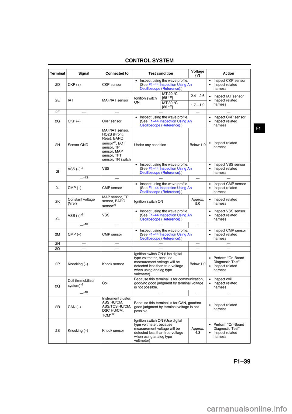
2D CKP (+) CKP sensor•Inspect using the wave profile.
(See F1–44 Inspection Using An
Oscilloscope (Reference).)•Inspect CKP sensor
•Inspect related
harness
2E IAT MAF/IAT sensorIgnition switch
ONIAT 20 °C
{68 °F}2.4—2.6
•Inspect IAT sensor
•Inspect related
harness IAT 30 °C
{86 °F}1.7—1.9
2F—— — ——
2G CKP (–) CKP sensor•Inspect using the wave profile.
(See F1–44 Inspection Using An
Oscilloscope (Reference).)•Inspect CKP sensor
•Inspect related
harness
2H Sensor GNDMAF/IAT sensor,
HO2S (Front,
Rear), BARO
sensor*
6, ECT
sensor, TP
sensor, MAP
sensor, TFT
sensor, TR switchUnder any condition Below 1.0•Inspect related
harness
2IVSS (–)*
8VSS•Inspect using the wave profile.
(See F1–44 Inspection Using An
Oscilloscope (Reference).)•Inspect VSS sensor
•Inspect related
harness
—*
13————
2J CMP (+) CMP sensor•Inspect using the wave profile.
(See F1–44 Inspection Using An
Oscilloscope (Reference).)•Inspect CMP sensor
•Inspect related
harness
2KConstant voltage
(Vref)MAP sensor, TP
sensor, BARO
sensor*
6Ignition switch ONApprox.
5.0•Inspect related
harness
2LVSS (+)*
8VSS•Inspect using the wave profile.
(See F1–44 Inspection Using An
Oscilloscope (Reference).)•Inspect VSS sensor
•Inspect related
harness
—*
13————
2M CMP (–) CMP sensor•Inspect using the wave profile.
(See F1–44 Inspection Using An
Oscilloscope (Reference).)•Inspect CMP sensor
•Inspect related
harness
2N—— — ——
2O—— — ——
2P Knocking (–) Knock sensorIgnition switch ON (Use digital
type voltmeter, because
measurement voltage will be
detected less than true voltage
when using analog type
voltmeter)Below 1.0•Perform “On-Board
Diagnostic Test”
•Inspect related
harness
2QCoil (Immobilizer
system)*
9CoilBecause this terminal is for communication,
good/no good judgment by terminal voltage
is not possible.•Inspect coil
•Inspect related
harness
—*
10————
2R CAN (–)Instrument cluster,
ABS HU/CM,
ABS/TCS HU/CM,
DSC HU/CM,
TCM*
12
Because this terminal is for CAN, good/no
good judgment by terminal voltage is not
possible.•Inspect related
harness
2S Knocking (+) Knock sensorIgnition switch ON (Use digital
type voltmeter, because
measurement voltage will be
detected less than true voltage
when using analog type
voltmeter)Approx.
4.3•Perform “On-Board
Diagnostic Test”
•Inspect related
harness Terminal Signal Connected to Test conditionVoltage
(V)Action
Page 128 of 909
F1–40
CONTROL SYSTEM
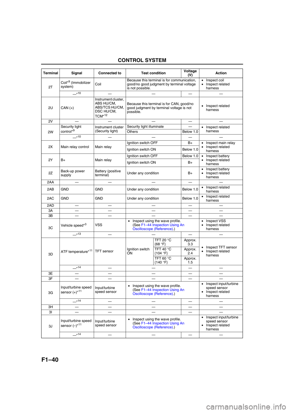
2TCoil*
9 (Immobilizer
system)CoilBecause this terminal is for communication,
good/no good judgment by terminal voltage
is not possible.•Inspect coil
•Inspect related
harness
—*
10————
2U CAN (+)Instrument cluster,
ABS HU/CM,
ABS/TCS HU/CM,
DSC HU/CM,
TCM*
12
Because this terminal is for CAN, good/no
good judgment by terminal voltage is not
possible.•Inspect related
harness
2V—— — ——
2WSecurity light
control*
9Instrument cluster
(Security light)Security light illuminate—
•Inspect related
harness
Others Below 1.0
—*
10————
2X Main relay control Main relayIgnition switch OFF B+•Inspect main relay
•Inspect related
harness Ignition switch ON Below 1.0
2Y B+ Main relayIgnition switch OFF Below 1.0•Inspect battery
•Inspect related
harness Ignition switch ON B+
2ZBack-up power
supplyBattery (positive
terminal)Under any condition B+•Inspect battery
•Inspect related
harness
2AA—— — ——
2AB GND GND Under any condition Below 1.0•Inspect related
harness
2AC GND GND Under any condition Below 1.0•Inspect related
harness
2AD—— — ——
3A—— — ——
3B—— — ——
3CVehicle speed*
3VSS•Inspect using the wave profile.
(See F1–44 Inspection Using An
Oscilloscope (Reference).)•Inspect VSS
•Inspect related
harness
—*
13————
3DATF temperature*
11TFT sensorIgnition switch
ONTFT 20 °C
{68 °F}Approx.
3.3
•Inspect TFT sensor
•Inspect related
harness TFT 40 °C
{104 °F}Approx.
2.4
TFT 60 °C
{140 °F}Approx.
1.5
—*
14————
3E—— — ——
3F—— — ——
3GInput/turbine speed
sensor (+)*
11Input/turbine
speed sensor•Inspect using the wave profile.
(See F1–44 Inspection Using An
Oscilloscope (Reference).)•Inspect input/turbine
speed sensor
•Inspect related
harness
—*
14————
3H—— — ——
3I—— — ——
3JInput/turbine speed
sensor (–)*
11Input/turbine
speed sensor•Inspect using the wave profile.
(See F1–44 Inspection Using An
Oscilloscope (Reference).)•Inspect input/turbine
speed sensor
•Inspect related
harness
—*
14———— Terminal Signal Connected to Test conditionVoltage
(V)Action
Page 140 of 909

F1–52
ON-BOARD DIAGNOSTIC
End Of Sie
DTC (4WD)A6E397018881204•Detection logics and conditions are as shown below.
Controller Area Network (CAN)
PCM cannot receive any signals from TCM (U0101)
•PCM cannot receive any signals from TCM.
End Of Sie
OBD DRIVE MODEA6E397018881205•Performing the Drive Mode inspects the OBD system for proper operation. The Drive Mode must be performed
to ensure that no additional DTCs are present.
•During Drive Mode, the following systems are inspected:
—Oxygen sensor (HO2S)
—Oxygen sensor heater
—Catalytic converter (TWC)
Caution
•While performing the Drive Mode, always operate the vehicle in a safe and lawful manner.
•When the WDS or equivalent is used to observe monitor system condition while driving, be sure to
have another technician with you, or record the data in the WDS or equivalent using the PID/DATA
MONITOR AND RECORD function and inspect later.
Note
•Vehicle speed and engine speed detected by the PCM may differ from that indicated by the speedometer
and tachometer. Use the WDS or equivalent to monitor vehicle speed.
•If the OBD system inspection is not completed during the Drive Mode, the following causes are
considered:
1. The OBD system detects the malfunction.
2. The Drive Mode procedure is not completed correctly.
•Disconnecting the battery will reset the memory. Do not disconnect the battery during and after Drive
Mode.
PCM Adaptive Memory Procedure Drive Mode
Note
•The PCM adaptive memory condition can be confirmed with RFCFLAG PID.
•If RFCFLAG PID is “Learnt”, PCM Adaptive Memory Procedure Drive Mode is not necessary, because
PCM already has adaptive memory.
•If RFCFLAG PID is “Not Learnt”, PCM Adaptive Memory Procedure Drive should be performed before
HO2S Heater, HO2S, and TWC Repair Verification Drive Mode.
1. Start the engine and warm it up completely.
2. Verify all accessory loads (A/C, headlights, blower fan, rear window defroster) are off.
U0101 PCM cannot receive any signals from TCM ON 1 Other×
U0121PCM cannot receive any signals from ABS, ABS/TCS
or DSC HU/CMON 1 Other×
U0155PCM cannot receive any signals from instrument
clusterON 1 Other× DTC No. Condition MIL DC Monitor itemMemory
function
Page 159 of 909

OUTLINE
F2–7
F2
End Of Sie
11 Generator
12 Oil pressure switch
13 Sedimentor switch
14 Instrument cluster
15 Neutral switch
16 Clutch switch
17 Coil
18 Brake switch
19 Brake switch 2
20 Cruise control switch
21 With cruise control system
22 PCM control relay
23 MAF/IAT sensor
24 Calibration resistor No.1
25 Fuel injector No.1
26 Calibration resistor No.2
27 Fuel injector No.2
28 Calibration resistor No.3
29 Fuel injector No.3
30 Calibration resistor No.4
31 Fuel injector No.4
32 CMP sensor
33 CKP sensor
34 EGR solenoid valve (vacuum)
35 EGR solenoid valve (vent)
36 VSC solenoid valve
37 Intake shutter solenoid valve (half)38 Intake shutter solenoid valve (full)
39 VBC solenoid valve
40 EGR control solenoid valve
41 Boost sensor
42 Accelerator position sensor
43 Idle switch
44 Fuel pressure sensor
45 ECT sensor
46 Fuel temperature sensor
47 Suction control valve
48 IAT sensor No.2
49 Cooling fan relay No.2
50 Cooling fan No.1
51 Refrigerant pressure switch (middle)
52 A/C switch
53 A/C amplifier
54 Cooling fan relay No.1
55 Cooling fan No.2
56 A/C relay
57 Refrigerant pressure switch (HI and LO)
58 Magnetic clutch
59 With A/C
60 Glow plug relay
61 Glow plug
62 Vacuum switch
63 Fuel warmer
64 With fuel warmer
Page 178 of 909

F2–26
ON-BOARD DIAGNOSTIC
End Of Sie
KOEO/KOER SELF-TESTA6E407018881203KOEO/KOER self-test function table
×: Applicable –: Not applicable
End Of Sie
P0610 Control module vehicle options error PCM data configuration error.××
P0661 VSC solenoid valve circuit low inputInput voltage from VSC solenoid valve is below 0.1
V.–×
P0662 VSC solenoid valve circuit high input Input voltage from VSC solenoid valve is above B+.–×
P0850 Neutral switch circuit malfunctionInput voltage from neutral switch does not change
when vehicle stops after accelerating to above 60
km/h {37 mph} and decelerating to 0 km/h {0 mph}
2 times.××
P1190 Calibration resistor circuit malfunctionInput voltage from calibration resistor is below 0.2 V
or above 4.8 V.××
P2228 BARO sensor circuit low input Input voltage from BARO sensor is below 0.7 V.××
P2229 BARO sensor circuit high input Input voltage from BARO sensor is above 4.5 V.××
U0073 CAN bus off CAN controller is damaged.–×
U0121PCM cannot receive any signals from
ABS, ABS/TCS or DSC HU/CMPCM cannot receive any signals from ABS, ABS/
TCS or DSC HU/CM.××
U0155PCM cannot receive any signals from
instrument clusterPCM cannot receive any signals from instrument
cluster.×× DTC Condition Detection condition MILMemory
function
DTC Condition KOEO KOER
P0097 IAT sensor No.1 circuit low input××
P0098 IAT sensor No.1 circuit high input××
P0102 MAF sensor circuit low input××
P0103 MAF sensor circuit high input××
P0107 Boost sensor circuit low input××
P0108 Boost sensor circuit high input××
P0112 IAT sensor No.2 circuit low input××
P0113 IAT sensor No.2 circuit high input××
P0117 ECT sensor circuit low input××
P0118 ECT sensor circuit high input××
P0122 Accelerator position sensor No.1 circuit low input××
P0123 Accelerator position sensor No.1 circuit high input××
P0222 Accelerator position sensor No.2 circuit low input××
P0223 Accelerator position sensor No.2 circuit high input××
P0602 PCM programming error××
P0610 Control module vehicle options error××
P0661 VSC solenoid valve circuit low input××
P0662 VSC solenoid valve circuit high input××
P2228 BARO sensor circuit low input××
P2229 BARO sensor circuit high input××
U0073 CAN bus off××
U0121 PCM cannot receive any signals from ABS, ABS/TCS or DSC HU/CM××
U0155 PCM cannot receive any signals from instrument cluster××
Page 204 of 909
F2–52
FUEL SYSTEM
SEDIMENTOR WATER DRAININGA6E4012348022041. Disconnect the negative battery cable.
2. Complete the “BEFORE REPAIR PROCEDURE”. (See F2–45 BEFORE REPAIR PROCEDURE.)
3. Loosen the drain plug located at the bottom of the fuel filter.
4. Pump the priming pump and drain the water.
5. After all the water has been drained, tighten the drain plug.
6. Complete the “AFTER REPAIR PROCEDURE”. (See F2–45 AFTER REPAIR PROCEDURE.)
7. Reconnect the negative battery cable.
End Of Sie
SEDIMENTOR SWITCH INSPECTIONA6E401213840201
Note
•Perform the following test only when directed.
1. Disconnect the negative battery cable.
2. Complete the “BEFORE REPAIR PROCEDURE”. (See F2–45 BEFORE REPAIR PROCEDURE.)
3. Drain fuel from the fuel filter. (See F2–52 SEDIMENTOR WATER DRAINING.)
4. Remove the sedimentor switch.
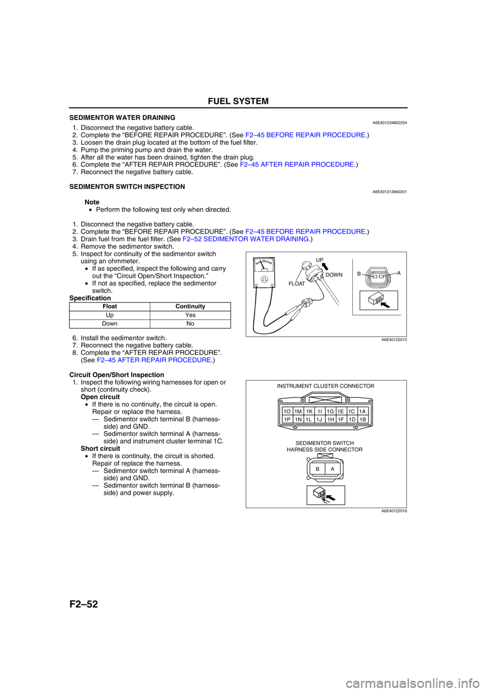
5. Inspect for continuity of the sedimentor switch
using an ohmmeter.
•If as specified, inspect the following and carry
out the “Circuit Open/Short Inspection.”
•If not as specified, replace the sedimentor
switch.
Specification
6. Install the sedimentor switch.
7. Reconnect the negative battery cable.
8. Complete the “AFTER REPAIR PROCEDURE”.
(See F2–45 AFTER REPAIR PROCEDURE.)
Circuit Open/Short Inspection
1. Inspect the following wiring harnesses for open or
short (continuity check).
Open circuit
•If there is no continuity, the circuit is open.
Repair or replace the harness.
—Sedimentor switch terminal B (harness-
side) and GND.
—Sedimentor switch terminal A (harness-
side) and instrument cluster terminal 1C.
Short circuit
•If there is continuity, the circuit is shorted.
Repair of replace the harness.
—Sedimentor switch terminal A (harness-
side) and GND.
—Sedimentor switch terminal B (harness-
side) and power supply.
End Of Sie
Float Continuity
Up Yes
Down No
UP
DOWN
FLOATA
B
A6E40122015
1O 1M 1K 1I 1G 1E 1C 1A
1P 1N 1L 1J 1H 1F 1D 1B INSTRUMENT CLUSTER CONNECTOR
SEDIMENTOR SWITCH
HARNESS SIDE CONNECTOR
A
B
A6E40122016
Page 218 of 909
F2–66
CONTROL SYSTEM
IAT
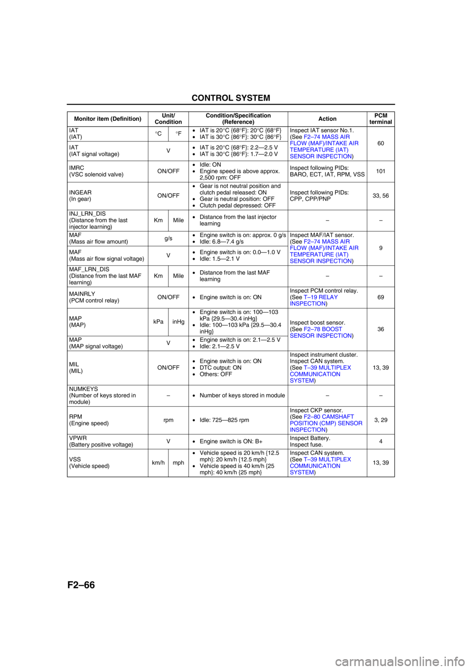
(IAT)°C°F•IAT is 20°C {68°F}: 20°C {68°F}
•IAT is 30°C {86°F}: 30°C {86°F}Inspect IAT sensor No.1.
(See F2–74 MASS AIR
FLOW (MAF)/INTAKE AIR
TEMPERATURE (IAT)
SENSOR INSPECTION)60
IAT
(IAT signal voltage)V•IAT is 20°C {68°F}: 2.2—2.5 V
•IAT is 30°C {86°F}: 1.7—2.0 V
IMRC
(VSC solenoid valve)ON/OFF•Idle: ON
•Engine speed is above approx.
2,500 rpm: OFFInspect following PIDs:
BARO, ECT, IAT, RPM, VSS101
INGEAR
(In gear)ON/OFF•Gear is not neutral position and
clutch pedal released: ON
•Gear is neutral position: OFF
•Clutch pedal depressed: OFFInspect following PIDs:
CPP, CPP/PNP33, 56
INJ_LRN_DIS
(Distance from the last
injector learning)Km Mile•Distance from the last injector
learning––
MAF
(Mass air flow amount)g/s•Engine switch is on: approx. 0 g/s
•Idle: 6.8—7.4 g/sInspect MAF/IAT sensor.
(See F2–74 MASS AIR
FLOW (MAF)/INTAKE AIR
TEMPERATURE (IAT)
SENSOR INSPECTION)9
MAF
(Mass air flow signal voltage)V•Engine switch is on: 0.0—1.0 V
•Idle: 1.5—2.1 V
MAF_LRN_DIS
(Distance from the last MAF
learning)Km Mile•Distance from the last MAF
learning––
MAINRLY
(PCM control relay)ON/OFF•Engine switch is on: ONInspect PCM control relay.
(See T–19 RELAY
INSPECTION)69
MAP
(MAP)kPa inHg•Engine switch is on: 100—103
kPa {29.5—30.4 inHg}
•Idle: 100—103 kPa {29.5—30.4
inHg}Inspect boost sensor.
(See F2–78 BOOST
SENSOR INSPECTION)36
MAP
(MAP signal voltage)V•Engine switch is on: 2.1—2.5 V
•Idle: 2.1—2.5 V
MIL
(MIL)ON/OFF•Engine switch is on: ON
•DTC output: ON
•Others: OFFInspect instrument cluster.
Inspect CAN system.
(See T–39 MULTIPLEX
COMMUNICATION
SYSTEM)13, 39
NUMKEYS
(Number of keys stored in
module)–•Number of keys stored in module––
RPM
(Engine speed)rpm•Idle: 725—825 rpmInspect CKP sensor.
(See F2–80 CAMSHAFT
POSITION (CMP) SENSOR
INSPECTION)3, 29
VPWR
(Battery positive voltage)V•Engine switch is ON: B+Inspect Battery.
Inspect fuse.4
VSS
(Vehicle speed)km/h mph•Vehicle speed is 20 km/h {12.5
mph}: 20 km/h {12.5 mph}
•Vehicle speed is 40 km/h {25
mph}: 40 km/h {25 mph}Inspect CAN system.
(See T–39 MULTIPLEX
COMMUNICATION
SYSTEM)13, 39 Monitor item (Definition)Unit/
ConditionCondition/Specification
(Reference)ActionPCM
terminal
Page 239 of 909
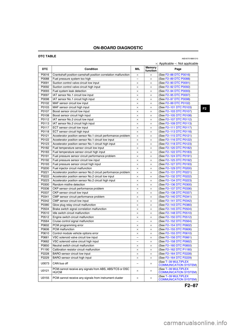
ON-BOARD DIAGNOSTIC
F2–87
F2
End Of SieDTC TABLEA6E407018881210
×: Applicable –: Not applicable
DTC Condition MILMemory
functionPage
P0016 Crankshaft position-camshaft position correlation malfunction××(See F2–88 DTC P0016)
P0088 Fuel pressure system too high–×(See F2–89 DTC P0088)
P0091 Suction control valve circuit low input××(See F2–90 DTC P0091)
P0092 Suction control valve circuit high input××(See F2–92 DTC P0092)
P0093 Fuel system leak detection××(See F2–94 DTC P0093)
P0097 IAT sensor No.1 circuit low input××(See F2–95 DTC P0097)
P0098 IAT sensor No.1 circuit high input××(See F2–97 DTC P0098)
P0102 MAF sensor circuit low input××(See F2–99 DTC P0102)
P0103 MAF sensor circuit high input××(See F2–101 DTC P0103)
P0107 Boost sensor circuit low input××(See F2–103 DTC P0107)
P0108 Boost sensor circuit high input××(See F2–105 DTC P0108)
P0112 IAT sensor No.2 circuit low input××(See F2–107 DTC P0112)
P0113 IAT sensor No.2 circuit high input××(See F2–109 DTC P0113)
P0117 ECT sensor circuit low input××(See F2–111 DTC P0117)
P0118 ECT sensor circuit high input××(See F2–113 DTC P0118)
P0121 Accelerator position sensor No.1 circuit performance problem××(See F2–115 DTC P0121)
P0122 Accelerator position sensor No.1 circuit low input××(See F2–116 DTC P0122)
P0123 Accelerator position sensor No.1 circuit high input××(See F2–118 DTC P0123)
P0182 Fuel temperature sensor circuit low input××(See F2–120 DTC P0182)
P0183 Fuel temperature sensor circuit high input××(See F2–122 DTC P0183)
P0191 Fuel pressure sensor circuit performance problem××(See F2–124 DTC P0191)
P0192 Fuel pressure sensor circuit low input××(See F2–125 DTC P0192)
P0193 Fuel pressure sensor circuit high input××(See F2–127 DTC P0193)
P0200 Fuel injector circuit malfunction××(See F2–129 DTC P0200)
P0221 Accelerator position sensor No.2 circuit performance problem××(See F2–131 DTC P0221)
P0222 Accelerator position sensor No.2 circuit low input××(See F2–132 DTC P0222)
P0223 Accelerator position sensor No.2 circuit high input××(See F2–134 DTC P0223)
P0300 Random misfire detection××(See F2–136 DTC P0300)
P0336 CKP sensor circuit performance problem××(See F2–137 DTC P0336)
P0337 CKP sensor circuit low input××(See F2–138 DTC P0337)
P0341 CMP sensor circuit performance problem××(See F2–140 DTC P0341)
P0342 CMP sensor circuit low input××(See F2–141 DTC P0342)
P0380 Glow plug relay circuit malfunction××(See F2–143 DTC P0380)
P0504 Brake switch signal correlation malfunction××(See F2–145 DTC P0504)
P0510 Idle switch circuit malfunction××(See F2–148 DTC P0510)
P0512 Engine switch circuit malfunction××(See F2–150 DTC P0512)
P0564 Cruise control signal malfunction–×(See F2–152 DTC P0564)
P0602 PCM programming error××(See F2–154 DTC P0602)
P0606 PCM malfunction××(See F2–155 DTC P0606)
P0610 Control module vehicle options error××(See F2–155 DTC P0610)
P0661 VSC solenoid valve circuit low input–×(See F2–156 DTC P0661)
P0662 VSC solenoid valve circuit high input–×(See F2–158 DTC P0662)
P0850 Neutral switch circuit malfunction××(See F2–160 DTC P0850)
P1190 Calibration resistor circuit malfunction××(See F2–162 DTC P1190)
P2228 BARO sensor circuit low input××(See F2–164 DTC P2228)
P2229 BARO sensor circuit high input××(See F2–164 DTC P2229)
U0073 CAN bus off–×(See T–39 MULTIPLEX
COMMUNICATION SYSTEM)
U0121PCM cannot receive any signals from ABS, ABS/TCS or DSC
HU/CM××(See T–39 MULTIPLEX
COMMUNICATION SYSTEM)
U0155 PCM cannot receive any signals from instrument cluster××(See T–39 MULTIPLEX
COMMUNICATION SYSTEM)
Page 326 of 909

F2–174
TROUBLESHOOTING
NO.2 MIL ILLUMINATESA6E408018881204
Diagnostic procedure
End Of Sie
NO.3 WILL NOT CRANKA6E408018881205
Diagnostic procedure
2 MIL ILLUMINATES
DESCRIPTION•MIL illuminates incorrectly.
POSSIBLE
CAUSE•PCM illuminates for emission-related concern (DTC is stored in PCM)
•Instrument cluster malfunction
Note
•If MIL blinks at steady rate, misfire condition could possibly exist.
STEP INSPECTION RESULTS ACTION
1 Connect WDS or equivalent to DLC-2.
Turn engine switch to ON.
Retrieve any DTC.
Is DTC displayed?YesDTC is displayed:
•Go to appropriate DTC test.
NoNo DTC is displayed:
•Inspect instrument cluster operation.
2 Verify test results.
•If okay, return to diagnostic index to service any additional symptoms.
•If malfunction remains, replace PCM. (See F2–64 PCM REMOVAL/INSTALLATION)
3 WILL NOT CRANK
DESCRIPTION•Starter does not work.
POSSIBLE
CAUSE•Open starter circuit between engine switch and starter
•Starter malfunction
•Seized/hydrolocked engine, flywheel
•Immobilizer system (PATS) and/or circuit malfunction (if equipped)
•Low or dead battery
•Charging system malfunction
STEP INSPECTION RESULTS ACTION
1Note
•The following test should be perform for
vehicles with immobilizer system. Go to
Step 10 for vehicles without immobilizer
system.
Connect WDS or equivalent to DLC-2.
Do following conditions appear?
•Engine is not completely started.
•DTC B1681 is displayed.YesBoth conditions appear:
Go to Step 4.
NoEither or other condition appears:
Go to next step.
2 Is coil connector securely connected to coil? Yes Go to next step.
No Connect coil connector securely.
Return to Step 1.
3 Does security light illuminate? Yes Go to next step.
No Inspect instrument cluster and wiring harness.
4 Connect WDS or equivalent to DLC-2 and
retrieve DTC.
DTC
B1213, B1342, B1600, B1601, B1602, B1681,
B2103, B2431Yes Go to appropriate DTC test.
No Go to next step.
Page 330 of 909

F2–178
TROUBLESHOOTING
End Of Sie
NO.5 ENGINE STALLS-AFTER START/AT IDLEA6E408018881207
Diagnostic Procedure
18 Verify test results.
•If okay, return to diagnostic index to service any additional symptoms.
•If malfunction remains, replace PCM. (See F2–64 PCM REMOVAL/INSTALLATION) STEP INSPECTION RESULTS ACTION
5 ENGINE STALLS-AFTER START/AT IDLE
DESCRIPTION•Engine stops unexpectedly.
POSSIBLE
CAUSE•Poor fuel quality
•Intake-air system restriction or clogging
•Engine overheating
•A/C system improper operation
•Immobilizer system (PATS) and/or circuit malfunction (if equipped)
•PCM control relay malfunction
•Glow system malfunction
•Inadequate fuel pressure
•Fuel pressure sensor related circuit malfunction
•Suction control valve malfunction (built-in supply pump)
•Fuel pressure limiter malfunction (built-in common rail)
•Fuel leakage
•Fuel line clogging or restriction
•Fuel filter clogging or restriction
•Incorrect fuel injection timing
•Erratic signal from CKP sensor
•Erratic signal from CMP sensor
•Supply pump malfunction
•Fuel injector malfunction
•Low engine compression
•Improper valve timing
•Exhaust system and/or catalyst converter restriction or clogging
•EGR system malfunction
•ECT sensor or related circuit malfunction
•Accelerator positions sensor or related circuit malfunction
•Accelerator positions sensor misadjustment
•MAF/IAT sensor or related circuit malfunction
•V-reference voltage supply circuit malfunction
•IDM or related circuit malfunction
Warning
The following troubleshooting flow chart contains the fuel system diagnosis and repair
procedures. Read the following warnings before performing the fuel system services:
•Fuel vapor is hazardous. It can easily ignite, causing serious injury and damage. Always keep
sparks and flames away from fuel.
•Fuel line spills and leakage are dangerous. Fuel can ignite and cause serious injury or death
and damage. Fuel can also irritate skin and eyes. To prevent this, always complete “BEFORE
REPAIR PROCEDURE” and “AFTER REPAIR PROCEDURE” described in this manual.
STEP INSPECTION RESULTS ACTION
1Note
•The following test should be perform for
vehicles with immobilizer system. Go to
Step 10 for vehicles without immobilizer
system.
Connect WDS or equivalent to DLC-2.
Do following conditions appear?
•Engine is not completely started.
•DTC B1681 is displayed.YesBoth conditions appear:
Go to Step 4.
NoEither or other condition appears:
Go to next step.
2 Is coil connector securely connected to coil? Yes Go to next step.
No Connect coil connector securely.
Return to Step 1.
3 Does security light illuminate? Yes Go to next step.
No Inspect instrument cluster and wiring harness.