change time MAZDA 6 2002 Workshop Manual Suplement
[x] Cancel search | Manufacturer: MAZDA, Model Year: 2002, Model line: 6, Model: MAZDA 6 2002Pages: 909, PDF Size: 17.16 MB
Page 3 of 909

WARNING
Servicing a vehicle can be dangerous. If you have not received
service-related training, the risks of injury, property damage, and
failure of servicing increase. The recommended servicing procedures
for the vehicle in this workshop manual were developed with
Mazda-trained technicians in mind. This manual may be useful to
non-Mazda trained technicians, but a technician with our
service-related training and experience will be at less risk when
performing service operations. However, all users of this manual are
expected to at least know general safety procedures.
This manual contains "Warnings" and "Cautions" applicable to risks
not normally encountered in a general technician's experience.
They should be followed to reduce the risk of injury and the risk that
improper service or repair may damage the vehicle or render it unsafe.
It is also important to understand that the "Warnings" and "Cautions"
are not exhaustive. It is impossible to warn of all the hazardous
consequences that might result from failure to follow the procedures.
The procedures recommended and described in this manual are
effective methods of performing service and repair. Some require tools
specifically designed for a specific purpose. Persons using procedures
and tools which are not recommended by Mazda Motor Corporation
must satisfy themselves thoroughly that neither personal safety nor
safety of the vehicle will be jeopardized.
The contents of this manual, including drawings and specifications, are
the latest available at the time of printing, and
Mazda Motor Corporation
reserves the right to change the vehicle designs and alter the contents
of this manual without notice and without incurring obligation.
Parts should be replaced with genuine Mazda replacement parts or
with parts which match the quality of genuine Mazda replacement
parts. Persons using replacement parts of lesser quality than that of
genuine Mazda replacement parts must satisfy themselves thoroughly
that neither personal safety nor safety of the vehicle will be
jeopardized.
Mazda Motor Corporation is not responsible for any problems which
may arise from the use of this manual. The cause of such problems
includes but is not limited to insufficient service-related training, use of
improper tools, use of replacement parts of lesser quality than that of
genuine Mazda replacement parts, or not being aware of any revision
of this manual.
Page 142 of 909
F1–54
ON-BOARD DIAGNOSTIC
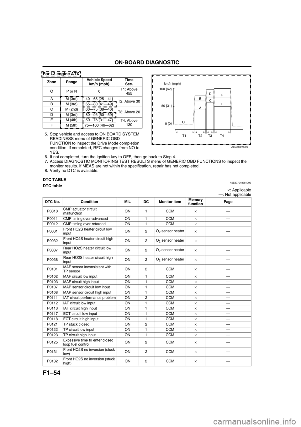
For L3 engine ATX
5. Stop vehicle and access to ON BOARD SYSTEM
READINESS menu of GENERIC OBD
FUNCTION to inspect the Drive Mode completion
condition. If completed, RFC changes from NO to
YES.
6. If not completed, turn the ignition key to OFF, then go back to Step 4.
7. Access DIAGNOSTIC MONITORING TEST RESULTS menu of GENERIC OBD FUNCTIONS to inspect the
monitor results. If MEAS are not within the specification, repair has not completed.
8. Verify no DTC is available.
End Of Sie
DTC TABLEA6E397018881206DTC table
×: Applicable
—: Not applicable
Zone RangeVehicle Speed
km/h {mph}Time
Sec.
OP or N 0T1: Above
455
A M (3rd) 40—65 {25—41}
T2: Above 30
B M (3rd) 65—80 {41—49}
C M (2nd) 60—75 {38—46}
T3: Above 20
D M (3rd) 80—95 {50—59}
EM (4th)50—75 {31—47}
T4: Above
120
FM (5th)75—100 {46—62}km/h {mph}
100 {62}
50 {31}
0 {0}O
T1 T2 T3 T4A BD
C
E F
A6E3970W999
DTC No. Condition MIL DC Monitor itemMemory
functionPage
P0010CMP actuator circuit
malfunctionON 1 CCM×—
P0011 CMP timing over-advanced ON 1 CCM×—
P0012 CMP timing over-retarded ON 1 CCM×—
P0031Front HO2S heater circuit low
inputON 2O
2 sensor heater
×—
P0032Front HO2S heater circuit high
inputON 2O
2 sensor heater
×—
P0037Rear HO2S heater circuit low
inputON 2O
2 sensor heater
×—
P0038Rear HO2S heater circuit high
inputON 2O
2 sensor heater
×—
P0101MAF sensor inconsistent with
TP sensorON 2 CCM×—
P0102 MAF circuit low input ON 1 CCM×—
P0103 MAF circuit high input ON 1 CCM×—
P0107 MAP sensor circuit low input ON 1 CCM×—
P0108 MAP sensor circuit high input ON 1 CCM×—
P0111 IAT circuit performance problem ON 2 CCM×—
P0112 IAT circuit low input ON 1 CCM×—
P0113 IAT circuit high input ON 1 CCM×—
P0117 ECT circuit low input ON 1 CCM×—
P0118 ECT circuit high input ON 1 CCM×—
P0121 TP stuck closed ON 2 CCM×—
P0122 TP circuit low input ON 1 CCM×—
P0123 TP circuit high input ON 1 CCM×—
P0125Excessive time to enter closed
loop fuel controlON 2 CCM×—
P0131Front HO2S no inversion (stuck
low)ON 2 CCM×—
P0132Front HO2S no inversion (stuck
high)ON 2 CCM×—
Page 178 of 909

F2–26
ON-BOARD DIAGNOSTIC
End Of Sie
KOEO/KOER SELF-TESTA6E407018881203KOEO/KOER self-test function table
×: Applicable –: Not applicable
End Of Sie
P0610 Control module vehicle options error PCM data configuration error.××
P0661 VSC solenoid valve circuit low inputInput voltage from VSC solenoid valve is below 0.1
V.–×
P0662 VSC solenoid valve circuit high input Input voltage from VSC solenoid valve is above B+.–×
P0850 Neutral switch circuit malfunctionInput voltage from neutral switch does not change
when vehicle stops after accelerating to above 60
km/h {37 mph} and decelerating to 0 km/h {0 mph}
2 times.××
P1190 Calibration resistor circuit malfunctionInput voltage from calibration resistor is below 0.2 V
or above 4.8 V.××
P2228 BARO sensor circuit low input Input voltage from BARO sensor is below 0.7 V.××
P2229 BARO sensor circuit high input Input voltage from BARO sensor is above 4.5 V.××
U0073 CAN bus off CAN controller is damaged.–×
U0121PCM cannot receive any signals from
ABS, ABS/TCS or DSC HU/CMPCM cannot receive any signals from ABS, ABS/
TCS or DSC HU/CM.××
U0155PCM cannot receive any signals from
instrument clusterPCM cannot receive any signals from instrument
cluster.×× DTC Condition Detection condition MILMemory
function
DTC Condition KOEO KOER
P0097 IAT sensor No.1 circuit low input××
P0098 IAT sensor No.1 circuit high input××
P0102 MAF sensor circuit low input××
P0103 MAF sensor circuit high input××
P0107 Boost sensor circuit low input××
P0108 Boost sensor circuit high input××
P0112 IAT sensor No.2 circuit low input××
P0113 IAT sensor No.2 circuit high input××
P0117 ECT sensor circuit low input××
P0118 ECT sensor circuit high input××
P0122 Accelerator position sensor No.1 circuit low input××
P0123 Accelerator position sensor No.1 circuit high input××
P0222 Accelerator position sensor No.2 circuit low input××
P0223 Accelerator position sensor No.2 circuit high input××
P0602 PCM programming error××
P0610 Control module vehicle options error××
P0661 VSC solenoid valve circuit low input××
P0662 VSC solenoid valve circuit high input××
P2228 BARO sensor circuit low input××
P2229 BARO sensor circuit high input××
U0073 CAN bus off××
U0121 PCM cannot receive any signals from ABS, ABS/TCS or DSC HU/CM××
U0155 PCM cannot receive any signals from instrument cluster××
Page 288 of 909
F2–136
ON-BOARD DIAGNOSTIC
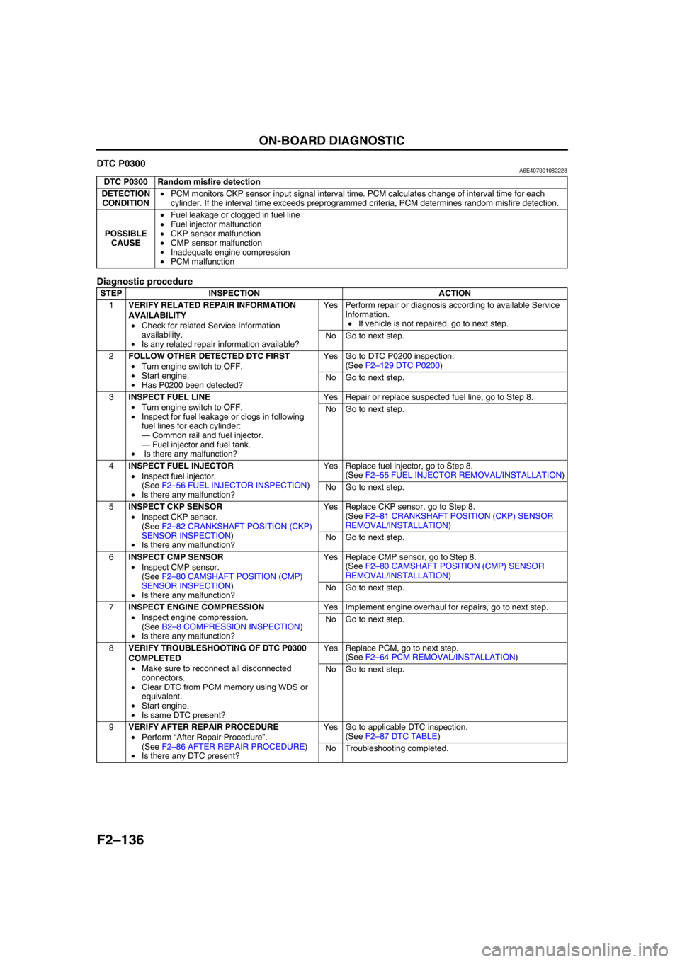
DTC P0300A6E407001082228
Diagnostic procedure
End Of Sie
DTC P0300 Random misfire detection
DETECTION
CONDITION•PCM monitors CKP sensor input signal interval time. PCM calculates change of interval time for each
cylinder. If the interval time exceeds preprogrammed criteria, PCM determines random misfire detection.
POSSIBLE
CAUSE•Fuel leakage or clogged in fuel line
•Fuel injector malfunction
•CKP sensor malfunction
•CMP sensor malfunction
•Inadequate engine compression
•PCM malfunction
STEP INSPECTION ACTION
1VERIFY RELATED REPAIR INFORMATION
AVAILABILITY
•Check for related Service Information
availability.
•Is any related repair information available?Yes Perform repair or diagnosis according to available Service
Information.
•If vehicle is not repaired, go to next step.
No Go to next step.
2FOLLOW OTHER DETECTED DTC FIRST
•Turn engine switch to OFF.
•Start engine.
•Has P0200 been detected?Yes Go to DTC P0200 inspection.
(See F2–129 DTC P0200)
No Go to next step.
3INSPECT FUEL LINE
•Turn engine switch to OFF.
•Inspect for fuel leakage or clogs in following
fuel lines for each cylinder:
—Common rail and fuel injector.
—Fuel injector and fuel tank.
• Is there any malfunction?Yes Repair or replace suspected fuel line, go to Step 8.
No Go to next step.
4INSPECT FUEL INJECTOR
•Inspect fuel injector.
(See F2–56 FUEL INJECTOR INSPECTION)
•Is there any malfunction?Yes Replace fuel injector, go to Step 8.
(See F2–55 FUEL INJECTOR REMOVAL/INSTALLATION)
No Go to next step.
5INSPECT CKP SENSOR
•Inspect CKP sensor.
(See F2–82 CRANKSHAFT POSITION (CKP)
SENSOR INSPECTION)
•Is there any malfunction?Yes Replace CKP sensor, go to Step 8.
(See F2–81 CRANKSHAFT POSITION (CKP) SENSOR
REMOVAL/INSTALLATION)
No Go to next step.
6INSPECT CMP SENSOR
•Inspect CMP sensor.
(See F2–80 CAMSHAFT POSITION (CMP)
SENSOR INSPECTION)
•Is there any malfunction?Yes Replace CMP sensor, go to Step 8.
(See F2–80 CAMSHAFT POSITION (CMP) SENSOR
REMOVAL/INSTALLATION)
No Go to next step.
7INSPECT ENGINE COMPRESSION
•Inspect engine compression.
(See B2–8 COMPRESSION INSPECTION)
•Is there any malfunction?Yes Implement engine overhaul for repairs, go to next step.
No Go to next step.
8VERIFY TROUBLESHOOTING OF DTC P0300
COMPLETED
•Make sure to reconnect all disconnected
connectors.
•Clear DTC from PCM memory using WDS or
equivalent.
•Start engine.
•Is same DTC present?Yes Replace PCM, go to next step.
(See F2–64 PCM REMOVAL/INSTALLATION)
No Go to next step.
9VERIFY AFTER REPAIR PROCEDURE
•Perform “After Repair Procedure”.
(See F2–86 AFTER REPAIR PROCEDURE)
•Is there any DTC present?Yes Go to applicable DTC inspection.
(See F2–87 DTC TABLE)
No Troubleshooting completed.
Page 312 of 909
F2–160
ON-BOARD DIAGNOSTIC
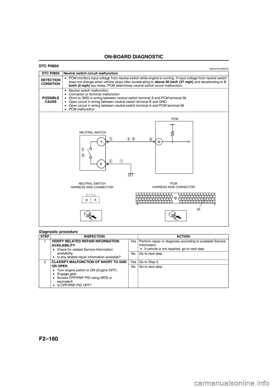
DTC P0850A6E407001082243
Diagnostic procedure
DTC P0850 Neutral switch circuit malfunction
DETECTION
CONDITION•PCM monitors input voltage from neutral switch while engine is running. If input voltage from neutral switch
does not change when vehicle stops after accelerating to above 60 km/h {37 mph} and decelerating to 0
km/h {0 mph} two times, PCM determines neutral switch circuit malfunction.
POSSIBLE
CAUSE•Neutral switch malfunction
•Connector or terminal malfunction
•Short to GND in wiring between neutral switch terminal A and PCM terminal 56
•Open circuit in wiring between neutral switch terminal B and GND
•Open circuit in wiring between neutral switch terminal A and PCM terminal 56
•PCM malfunction
STEP INSPECTION ACTION
1VERIFY RELATED REPAIR INFORMATION
AVAILABILITY
•Check for related Service Information
availability.
•Is any related repair information available?Yes Perform repair or diagnosis according to available Service
Information.
•If vehicle is not repaired, go to next step.
No Go to next step.
2CLASSIFY MALFUNCTION OF SHORT TO GND
OR OPEN
•Turn engine switch to ON (Engine OFF).
•Engage gear.
•Access CPP/PNP PID using WDS or
equivalent.
•Is CPP/PNP PID OFF?Yes Go to Step 5.
No Go to next step.
A
B
A
B NEUTRAL SWITCH
56PCM
56
3
6
5
5
7
498
NEUTRAL SWITCH
HARNESS SIDE CONNECTORPCM
HARNESS SIDE CONNECTOR
Page 474 of 909
AUTOMATIC TRANSAXLE
K2–59
K2
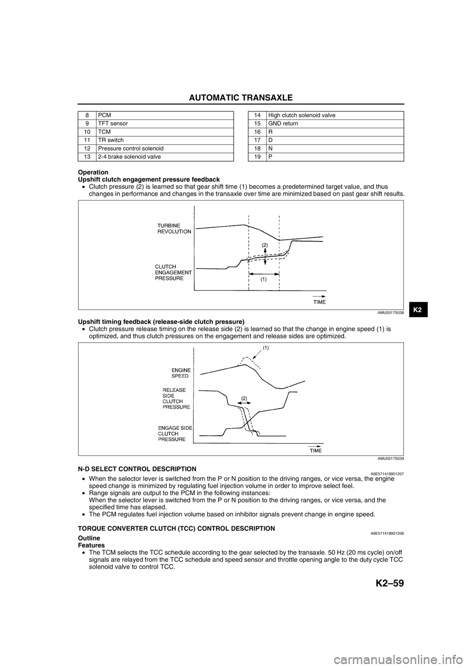
Operation
Upshift clutch engagement pressure feedback
•Clutch pressure (2) is learned so that gear shift time (1) becomes a predetermined target value, and thus
changes in performance and changes in the transaxle over time are minimized based on past gear shift results.
Upshift timing feedback (release-side clutch pressure)
•Clutch pressure release timing on the release side (2) is learned so that the change in engine speed (1) is
optimized, and thus clutch pressures on the engagement and release sides are optimized.
End Of SieN-D SELECT CONTROL DESCRIPTIONA6E571418901207•When the selector lever is switched from the P or N position to the driving ranges, or vice versa, the engine
speed change is minimized by regulating fuel injection volume in order to improve select feel.
•Range signals are output to the PCM in the following instances:
When the selector lever is switched from the P or N position to the driving ranges, or vice versa, and the
specified time has elapsed.
•The PCM regulates fuel injection volume based on inhibitor signals prevent change in engine speed.
End Of Sie
TORQUE CONVERTER CLUTCH (TCC) CONTROL DESCRIPTIONA6E571418901208Outline
Features
•The TCM selects the TCC schedule according to the gear selected by the transaxle. 50 Hz (20 ms cycle) on/off
signals are relayed from the TCC schedule and speed sensor and throttle opening angle to the duty cycle TCC
solenoid valve to control TCC.
8PCM
9 TFT sensor
10 TCM
11 TR switch
12 Pressure control solenoid
13 2-4 brake solenoid valve14 High clutch solenoid valve
15 GND return
16 R
17 D
18 N
19 P
AMU0517S038
AMU0517S039
Page 543 of 909

K2–128
ON-BOARD DIAGNOSTIC
End Of Sie
3VERIFY CURRENT INPUT SIGNAL STATUS-IS
CONCERN INTERMITTENT OR CONSTANT?
•Connect volt meter to TCM.
•Turn ignition key to ON (engine OFF).
•Inspect TCM terminal voltages.
(See K2–90 TCM INSPECTION.)
—TCM terminal 2B
•P position: B+
•Other positions and all ranges: 0V
—TCM terminal 1W
•R position: B+
•Other positions and all ranges: 0V
—TCM terminal 1T
—N position: B+
—Other positions and all ranges: 0V
—TCM terminal 1Z
•D range: B+
•Other ranges and all positions: 0V
•Are two or more of following terminal voltage at
the same time when shifting selector lever from
P position to D range?Yes Go to next step.
No Go to intermittent concern troubleshooting procedure.
(See section F1.)
4INSPECT TR SWITCH CONNECTOR
•Turn ignition key OFF.
•Disconnect TR switch connector.
•Inspect bent terminals of pins using mirror.
•Are TR switch terminals okay?Yes Go to next step.
No Repair terminals or replace TR switch, then go to Step 8.
(See K2–81 TRANSAXLE RANGE (TR) SWITCH
REMOVAL/INSTALLATION.)
5INSPECT TR SWITCH CIRCUIT MALFUNCTION
•Connect voltmeter to TCM.
•Turn ignition key to ON (engine OFF).
•Does TCM terminal voltage change from B+ to
0V when TR switch connector is disconnected?Yes Go to next step.
No Go to Step 7.
6INSPECT TR SWITCH CONTINUITY
•Turn ignition key to OFF.
•Disconnect TR switch connector.
•Inspect TR switch for continuity in positions/
ranges failed in Step 4.
•Is there continuity between TR switch terminals
(part side)?
(See K2–80 TRANSAXLE RANGE (TR) SWITCH
INSPECTION.)Yes Go to Step 8.
No Replace TR switch, then go to Step 8.
(See K2–81 TRANSAXLE RANGE (TR) SWITCH
REMOVAL/INSTALLATION.)
7INSPECT TR SWITCH CIRCUIT FOR SHORT TO
POWER
•Turn ignition key to ON (engine OFF).
•Measure voltage at TR switch terminal A, E, D,
G, I, and F (harness-side).
•Is there 0 V at TR switch harness side
connector?Yes Go to next step.
No Repair or replace wiring, then go to next step.
8VERIFY TROUBLESHOOTING OF DTC P0705
COMPLETED
•Make sure to reconnect all disconnected
connectors.
•Clear DTC from memory using WDS or
equivalent.
•Turn ignition key to on (engine off).
•Drive vehicle in each range (P, R, N, and D) for
5 seconds or more.
•Is same DTC present?Yes Replace TCM, then go to next step.
(See K2–96 TCM REMOVAL/INSTALLATION.)
No Go to next step.
9VERIFY AFTER REPAIR PROCEDURE
•Perform “After Repair Procedure”.
(See K2–124 AFTER REPAIR PROCEDURE.)
•Is there any DTC present?Yes Go to applicable DTC inspection.
No Troubleshooting completed. STEP INSPECTION ACTION
Page 743 of 909

P–10
OUTLINE , GENERAL PROCEDURES
SUPPLEMENTAL SERVICE INFORMATIONA6E690201020205•The following changes have been made since publication of the Mazda6 Workshop Manual (1730-1*-02C).
Power brake unit
•Removal/installation procedure has been modified.
Vacuum switch (MZR-CD (RF Turbo))
•Inspection procedure has been added.
•Removal/installation procedure has been added.
Vacuum pump (MZR-CD (RF Turbo))
•Inspection procedure has been added.
•Removal/installation procedure has been added.
Front brake (disc)
•Inspection procedure has been modified.
•Removal/installation procedure has been modified.
Disc pad (front)
•Replacement procedure has been modified.
Parking brake (lever type)
•Adjustment procedure has been modified.
DSC HU/CM
•Inspection procedure has been modified.
Combine sensor (Forward-G sensor)
•Inspection procedure has been modified.
On-board diagnostic (ABS/TCS)
•4WD and MZR-CD (RF Turbo) have been added.
End Of Sie
PRECAUTION (BRAKES)A6E691001020201Wheels and Tires Removal/Installation
1. The removal and installation procedures for the wheels and tires are not mentioned in this section. When a
wheel is removed, tighten it to 88—118 N·m {9.0—12.0 kgf·m, 65.0—87.0 ft·lbf}.
Brake Lines Disconnection/Connection
Caution
•Brake fluid will damage painted surfaces. If brake fluid does get on a painted surface, wipe it off
immediately.
1. Tighten the brake pipe flare nut using the SST (49 0259 770B). Be sure to modify the brake pipe flare nut
tightening torque to allow for use of a torque wrench-SST combination.
•If any brake line has been disconnected anytime during the procedure, add brake fluid, bleed the brakes,
and inspect for leakage after the procedure has been completed.
Connectors Disconnection
1. Disconnect the negative battery cable before doing any work that requires handling of connectors. Reconnect
the negative battery cable only after the work is completed.
ABS, ABS/TCS, or DSC Components Operations
1. Make sure that there are no DTCs in the ABS, ABS/TCS, or DSC memory after working on ABS, ABS/TCS or
DSC components.
•If there are any DTCs in the memory, clear them.
End Of Sie
OUTLINE
GENERAL PROCEDURES
Page 760 of 909

ON-BOARD DIAGNOSTIC
P–27
P
Diagnostic procedure
End Of Sie
DTC C1949, C1950A6E697067650203
Caution
•When attaching the tester lead to the DSC HU/CM connector, the SST (49 G066 004) must be used.
STEP INSPECTION ACTION
1CHECK FOR PCM FOR DTCs
•Turn ignition key to OFF.
•Connect WDS or equivalent to DLC-2
•Turn ignition key to ON (engine OFF).
•Is DTC for engine control system obtained?Yes Follow inspection procedures for engine control system.
No Go to next step.
2MONITOR CAN SIGNAL
•Access PID RPM and TP using WDS or
equivalent.
•Are engine speed and throttle position within
specification?Yes Go to next step.
No Follow inspection procedures for engine control system.
3VERIFY TROUBLESHOOTING COMPLETED
•Make sure to reconnect all disconnected
connectors.
•Clear DTC from memory.
•Start engine.
•Is same DTC present?Yes Replace DSC HU/CM, then go to next step.
No Troubleshooting completed.
DTC C1949, C1950 Combine sensor (forward G-sensor)
DETECTION
CONDITION•C1949:
—Monitor voltage of forward-G sensor is detected at 4.5 V or more, or 0.5 V or less.
—Monitor voltage difference of 0.4 V or more within 1 cycle is detected 8 times in 1 second.
•C1950:
—Forward-G sensor 0-point correction value is default or more
—Output voltage value from G sensor remains absolutely unchanged
—Difference between estimated G-force calculated from 2 channels exceeds specification
POSSIBLE
CAUSE•Open circuit in harness between combine sensor terminal C and DSC HU/CM terminal P
•Open circuit, short to power, or short to ground in harness between DSC HU/CM terminal V and
combine sensor terminal A
•Open circuit, short to power, or short to ground in harness between DSC HU/CM terminal S and
combine sensor terminal F
•Open circuit in harness between combine sensor terminal E and DSC HU/CM terminal Y
•Malfunction of combine sensor
Page 886 of 909
ON-BOARD DIAGNOSTIC
U–22–1
U
U–22H EA TER AND A I R C O NDI T ION ER SYST EMS
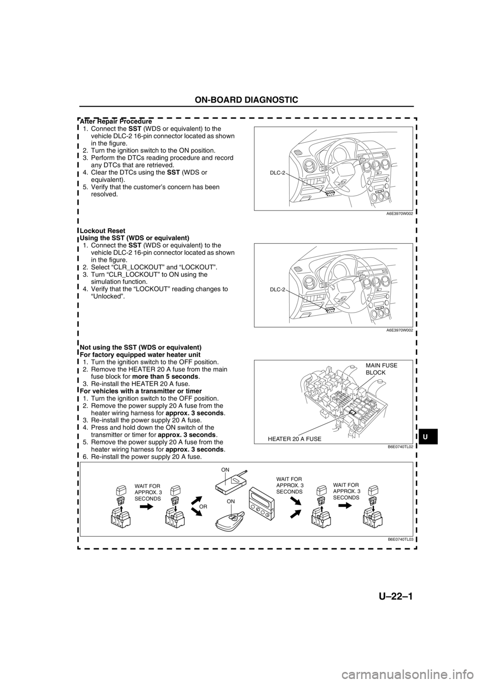
After Repair Procedure
1. Connect the SST (WDS or equivalent) to the
vehicle DLC-2 16-pin connector located as shown
in the figure.
2. Turn the ignition switch to the ON position.
3. Perform the DTCs reading procedure and record
any DTCs that are retrieved.
4. Clear the DTCs using the SST (WDS or
equivalent).
5. Verify that the customer’s concern has been
resolved.
Lockout Reset
Using the SST (WDS or equivalent)
1. Connect the SST (WDS or equivalent) to the
vehicle DLC-2 16-pin connector located as shown
in the figure.
2. Select “CLR_LOCKOUT” and “LOCKOUT”.
3. Turn “CLR_LOCKOUT” to ON using the
simulation function.
4. Verify that the “LOCKOUT” reading changes to
“Unlocked”.
Not using the SST (WDS or equivalent)
For factory equipped water heater unit
1. Turn the ignition switch to the OFF position.
2. Remove the HEATER 20 A fuse from the main
fuse block for more than 5 seconds.
3. Re-install the HEATER 20 A fuse.
For vehicles with a transmitter or timer
1. Turn the ignition switch to the OFF position.
2. Remove the power supply 20 A fuse from the
heater wiring harness for approx. 3 seconds.
3. Re-install the power supply 20 A fuse.
4. Press and hold down the ON switch of the
transmitter or timer for approx. 3 seconds.
5. Remove the power supply 20 A fuse from the
heater wiring harness for approx. 3 seconds.
6. Re-install the power supply 20 A fuse.
ON-BOARD DIAGNOSTIC
DLC-2
A6E3970W002
DLC-2
A6E3970W002
HEATER 20 A FUSE
MAIN FUSE
BLOCK
B6E0740TL02
WAIT FOR
APPROX. 3
SECONDS
OR
ON
ONWAIT FOR
APPROX. 3
SECONDS WAIT FOR
APPROX. 3
SECONDS
B6E0740TL03