4WD MAZDA 6 2002 Workshop Manual Suplement
[x] Cancel search | Manufacturer: MAZDA, Model Year: 2002, Model line: 6, Model: MAZDA 6 2002Pages: 909, PDF Size: 17.16 MB
Page 6 of 909

VIN CODE
GI–3
GIVIN CODEA6E200800021201European (L.H.D. U.K.) specs.GCC specs.End Of Sie
VIN CODE
Serial No.
0=Hiroshima
2=5MT For Europe(U.K.): Dummy
For Europe(L.H.D.): Dummy
For Israel: Model year0
3 to 9
3=2003
3=2.3L (L3)
8=1.8L (L8)
F=2.0L (LF)
R=MZR-CD(RF-Turbo)-Hi
T=MZR-CD(RF-Turbo)-Low5=4EAT
7=5EAT
8=4WD
1=2WD
GG=MAZDA6 (4SD, 5HB)
GY=MAZDA6 (WAGON)
JMZ=Europe(L.H.D. U.K.)2=4SD
4=5HB
9=WAGON 1=Hofu Plant
Engine typeWorld manufacturer identification
Body style
Remarks
Vehicle type
Transmission
A6E2021T101
J M 7 G Y 3 9 F * 3 # 1 2 3 4 5 6
Serial No.
0= Hiroshima
1= Hofu
0 to 9, X
F= 2.0L (LF)
9= WAGON 4= 5HB 2= 4SD
JM7= General (L.H.D.) 3= Without side air bag
4= With side air bag
GY= MAZDA6 (WAGON) GG= MAZDA6 (4SD, 5HB) Plant
For Saudi: Model year
For Model year: Dummy
Body style Engine typeCheck digit3
0 - 9
Restraint system
Vehicle type
World manufacturer identification
A6E2010T102
Page 7 of 909

GI–4
FUNDAMENTAL PROCEDURES
DYNAMOMETERA6E2014000042174WD testing/servicing
•Brake tester
Caution
•
To ensure the stability of the drag force of the viscous coupling always perform a brake test after
using the dynamometer or speed meter tester.
Note
•If there is a great amount of brake drag, it is probably due to the viscosity of the viscous coupling or the
center differential (RBC). To remove the influence of the coupling, jack up all four wheels of the vehicle
and verify that each wheel can be rotated freely by hand.
•Chassis dynamometer/speed meter tester
Caution
•
The vehicle may sway or surge forward when on the dynamometer. To prevent possible vehicle
movement, firmly secure it in place using steel retainers (chain, wire or similar) attached to the
front and rear towing hooks or to the tie down hooks.
•
Do not pop the clutch.
•
Do not accelerate suddenly.
Note
•The dynamometer/speed meter tester has two setting modes: propeller shaft removed mode and free
roller mode. After placing the vehicle on the tester and setting the wheels on the free rollers, start the
engine. For MTX vehicles, set the shift lever into second gear and gently, at low idle speed, release the
clutch pedal. For ATX vehicles, set the selector lever to D range, and slowly accelerate.
End Of Sie
FUNDAMENTAL PROCEDURES
Page 10 of 909

ABBREVIATIONS
GI–7
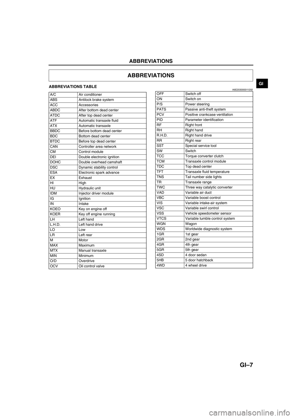
GIABBREVIATIONS TABLEA6E203000011202
End Of Sie
ABBREVIATIONS
A/C Air conditioner
ABS Antilock brake system
ACC Accessories
ABDC After bottom dead center
ATDC After top dead center
ATF Automatic transaxle fluid
ATX Automatic transaxle
BBDC Before bottom dead center
BDC Bottom dead center
BTDC Before top dead center
CAN Controller area network
CM Control module
DEI Double electronic ignition
DOHC Double overhead camshaft
DSC Dynamic stability control
ESA Electronic spark advance
EX Exhaust
HI High
HU Hydraulic unit
IDM Injector driver module
IG Ignition
IN Intake
KOEO Key on engine off
KOER Key off engine running
LH Left hand
L.H.D. Left hand drive
LO Low
LR Left rear
M Motor
MAX Maximum
MTX Manual transaxle
MIN Minimum
O/D Overdrive
OCV Oil control valveOFF Switch off
ON Switch on
P/S Power steering
PATS Passive anti-theft system
PCV Positive crankcase ventilation
PID Parameter identification
RF Right front
RH Right hand
R.H.D. Right hand drive
RR Right rear
SST Special service tool
SW Switch
TCC Torque converter clutch
TCM Transaxle control module
TDC Top dead center
TFT Transaxle fluid temperature
TNS Tail number side lights
TR Transaxle range
TWC Three way catalytic converter
VAD Variable air duct
VBC Variable boost control
VIS Variable intake-air system
VSC Variable swirl control
VSS Vehicle speedometer sensor
VTCS Variable tumble control system
WGN Wagon
WDS Worldwide diagnostic system
1GR 1st gear
2GR 2nd gear
4GR 4th gear
5GR 5th gear
4SD 4 door sedan
5HB 5 door hatchback
4WD 4 wheel drive
Page 12 of 909

SCHEDULED MAINTENANCE
GI–9
GI
Engine coolantReplace at first 4 years or 100,000 km (62,500 miles);
after that, every 2 years
Fuel lines & hoses I I I I
Battery electrolyte level & specific gravity I I I I I I I I I
Brake fluid *3 R R R R
Brake lines, hoses & connections I I I I I I I I I
Parking brake I I I I I I I I I
Power brake unit & hoses I I I I I I I I I
Disc brakes IIIIIIIII
Power steering fluid, lines, hoses, and connections I I I I I I I I I
Steering operation & linkages I I I I
Manual transaxle oil R
Automatic transaxle fluid level I I I
Rear differential oil (for 4WD)
*7*8
Transfer oil (for 4WD)
*8
Front & rear suspension & ball joints I I I I
Driveshaft dust boots I I I I
Exhaust system & heat shields I I I I
Cabin air filter (if installed) (aldehyde filter) R R R R R R R R R
Cabin air filter (if installed)(pollen filter) R R R R
Body condition
(for rust, corrosion & perforation)Inspect annually
Bolts & nuts on seats I I I IMaintenance ItemMaintenance Interval (Number of months or km (miles), whichever comes first)
Months 12 24 36 48 60 72 84 96 108
×1000 km 20 40 60 80 100 120 140 160 180
×1000 miles 12.5 25 37.5 50 62.5 75 87.5 100 112.5
Page 15 of 909

SCHEDULED MAINTENANCE
GI–11–1
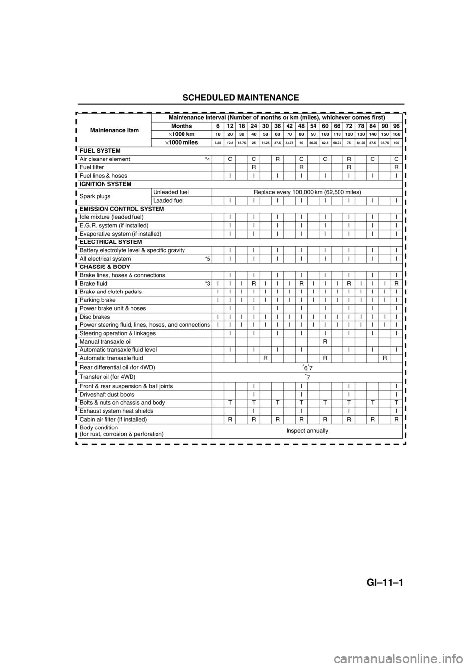
GI–11GE NERAL INFORMATION
End Of Sie
SCHEDU LED MAINTENANCE
Maintenance ItemMaintenance Interval (Number of months or km (miles), whichever comes first)
Months 6 121824303642485460667278849096
×1000 km10 20 30 40 50 60 70 80 90 100 110 120 130 140 150 160
×1000 miles6.25 12.5 18.75 25 31.25 37.5 43.75 50 56.25 62.5 68.75 75 81.25 87.5 93.75 100
FUEL SYSTEM
Air cleaner element *4CCRCCRCC
Fuel filter R R R R
Fuel lines & hoses IIIIIIII
IGNITION SYSTEM
Spark plugs Unleaded fuel Replace every 100,000 km (62,500 miles)
Leaded fuel IIIIIIII
EMISSION CONTROL SYSTEM
Idle mixture (leaded fuel) IIIIIIII
E.G.R. system (if installed) IIIIIIII
Evaporative system (if installed) IIIIIIII
ELECTRICAL SYSTEM
Battery electrolyte level & specific gravity IIIIIIII
All electrical system *5IIIIIIII
CHASSIS & BODY
Brake lines, hoses & connections IIIIIIII
Brake fluid *3 I I I R I I I R I I I R I I I R
Brake and clutch pedals IIIIIIIIIIIIIIII
Parking brake IIIIIIIIIIIIIIII
Power brake unit & hosesIIIIIIII
Disc brakes IIIIIIIIIIIIIIII
Power steering fluid, lines, hoses, and connections I I I I I I I I I I I I I I I I
Steering operation & linkages IIIIIIII
Manual transaxle oilR
Automatic transaxle fluid level IIII III
Automatic transaxle fluid R R R
Rear differential oil (for 4WD)
*6*7
Transfer oil (for 4WD)
*7
Front & rear suspension & ball joints I I I I
Driveshaft dust boots I I I I
Bolts & nuts on chassis and body TTTTTTTT
Exhaust system heat shields I I I I
Cabin air filter (if installed) RRRRRRRR
Body condition
(for rust, corrosion & perforation)Inspect annually
Page 17 of 909

SCHEDULED MAINTENANCE
GI–13
GI
For Israel
Applied VIN (assumed):
JMZ GG1235✻
✻✻ ✻
# 202316-, JMZ GG1435✻
✻✻ ✻
# 202316-, JMZ GY19F2✻
✻✻ ✻
# 146118-, JMZ GY19F5✻
✻✻ ✻
# 146118-
Chart symbols:
I : Inspect and clean, repair, adjust, or replace if necessary.
R : Replace
C : Clean
Remarks:
Engine oil *1 R R R R R R R R R
Engine oil filter *1RRRRRRRRR
Drive belts *2 I I I
Cooling system (including coolant level adjustment) I I I I
Engine coolantReplace at first 4 years or 100,000 km (62,500 miles);
after that, every 2 years
Fuel lines and hoses I I I I
Battery electrolyte level and specific gravity IIIIIIIII
Brake fluid *3 R R R R
Brake lines, hoses and connections IIIIIIIII
Parking brake IIIIIIIII
Power brake unit and hoses IIIIIIIII
Disc brakes IIIIIIIII
Power steering fluid, lines, hoses, and connections IIIIIIIII
Steering operation and linkages I I I I
Manual transaxle oil R
Automatic transaxle fluid level I I I
Rear differential oil (for 4WD)
*7*8
Transfer oil (for 4WD)
*8
Front and rear suspension and ball joints I I I I
Driveshaft dust boots I I I I
Exhaust system and heat shields I I
Cabin air filter (if installed) (pollen filter) R R R R
Body condition
(for rust, corrosion and perforation)Inspect annually
Tires (including spare tyre)
(with inflation pressure adjustment)IIIIIIIII Maintenance ItemMaintenance Interval (Number of months or km (miles), whichever comes first)
Months 12 24 36 48 60 72 84 96 108
×1000 km 20 40 60 80 100 120 140 160 180
×1000 miles 12.5 25 37.5 50 62.5 75 87.5 100 112.5
•The ignition and fuel systems are highly important to the emission control system and to efficient engine operation. All
inspections and adjustments must be made by an Authorized Mazda Dealer.
•After the prescribed period, continue to follow the described maintenance at the recommended intervals.
•Refer below for a description of items marked* in the maintenance chart.
*1: If the vehicle is operated under any of the following conditions, change the engine oil and oil filter every 10,000 km
(6,250 miles) or shorter.
a. Driving in dusty conditions.
b. Extended periods of idling or low speed operation.
c. Driving for long period in cold temperatures or driving regularly at short distance only.
*2: Also inspect and adjust the power steering and air conditioner drive belts, if installed.
*3: If the brakes are used extensively (for example, continuous hard driving or mountain driving) or if the vehicle is
operated in extremely humid climates, change the brake fluid annually.
*4: If the vehicle is operated in very dusty or sandy areas, clean and if necessary, replace the air cleaner element more
often than the recommended intervals.
*5: This is a full function check of electrical systems such as lights, wiper and washer systems (including wiper blades),
and power windows.
Page 20 of 909

GI–16
SCHEDULED MAINTENANCE
Evaporative system (if installed) IIIIIIII
ELECTRICAL SYSTEM
Battery electrolyte level and specific gravity IIIIIIII
All electrical system *5IIIIIIII
CHASSIS AND BODY
Brake lines, hoses and connections IIIIIIII
Brake fluid *3IIIRIIIRIIIRIIIR
Parking brake IIIIIIIIIIIIIIII
Power brake unit and hoses IIIIIIII
Disc brakes IIIIIIIIIIIIIIII
Power steering fluid, lines, hoses, and connections I I I I I I I I I I I I I I I I
Steering operation and linkages IIIIIIII
Manual transaxle oilR
Automatic transaxle fluid level IIIIIIII
Rear differential oil (for 4WD)
*6*7
Transfer oil (for 4WD)
*7
Front and rear suspension and ball joints I I I I
Driveshaft dust boots I I I I
Bolts and nuts on chassis and body TTTTTTTT
Exhaust system and heat shields Inspect every 80,000 km (50,000 miles)
Cabin air filter (if installed) RRRRRRRR
Body condition
(for rust, corrosion and perforation)Inspect annually
Tyres (including spare tyre)
(with inflation pressure adjustment)IIIIIIII Maintenance ItemMaintenance Interval (Number of months or km (miles), whichever comes first)
Months 6 121824303642485460667278849096
×1000 km
10 20 30 40 50 60 70 80 90 100 110 120 130 140 150 160
×1000 miles6.25 12.5 18.75 25 31.25 37.5 43.75 50 56.25 62.5 68.75 75 81.25 87.5 93.75 100
Page 23 of 909
![MAZDA 6 2002 Workshop Manual Suplement B1–1
B1
B1ENGINE [L8, LF, L3]
OUTLINE.............................................................. B1-2
OUTLINE OF CONSTRUCTION........................ B1-2
FEATURES ............................... MAZDA 6 2002 Workshop Manual Suplement B1–1
B1
B1ENGINE [L8, LF, L3]
OUTLINE.............................................................. B1-2
OUTLINE OF CONSTRUCTION........................ B1-2
FEATURES ...............................](/img/28/57057/w960_57057-22.png)
B1–1
B1
B1ENGINE [L8, LF, L3]
OUTLINE.............................................................. B1-2
OUTLINE OF CONSTRUCTION........................ B1-2
FEATURES ........................................................ B1-2
ENGINE PERFORMANCE CURVE ................... B1-2
SPECIFICATIONS ............................................. B1-3
OUTLINE.............................................................. B1-4
SUPPLEMENTAL SERVICE INFORMATION ... B1-4
ENGINE................................................................ B1-4
ENGINE REMOVAL/INSTALLATION (4WD) ..... B1-4 FEATURES
SERVICE
Page 24 of 909

B1–2
OUTLINE
OUTLINE OF CONSTRUCTIONA6E220202000201•The construction and operation of the new Mazda6 (GG, GY) L8, LF, and L3 engine is the same as that of the
current Mazda6 (GG) L8, LF, and L3 engine models except for the following features. (See Mazda6 training
Manual 3359-1*-02C.)
End Of Sie
FEATURESA6E220202000202Modification to the engine performance
•Engine performance curve has been changed. (4WD model)
End Of Sie
ENGINE PERFORMANCE CURVEA6E220202000203
End Of Sie
OUTLINE
1 Engine speed
2Output
3Torque
4 Current 2WD model (L3)
5 New 4WD model (L3)
0
7,000 6,000 5,000 4,000 3,000 2,000 1,000 10 20
30
40
50
60
70
80
90 100
110
120
130270
200
180
160
140
1200
7,000 6,000 5,000 4,000 3,000 2,000 1,000 10 20
30
40
50
60
70
80
90 100
110
120
130270
200
180
160
140
120 205N·m/4,000rpm
119kW/6,500rpm
3
1
2
(rpm) (kw)(N
·m)
5
207N·m/4000rpm
122kW/6500rpm
3
1
2
(rpm) (kw)(N
·m)
4
A6E2202N201
Page 26 of 909

B1–4
OUTLINE, ENGINE
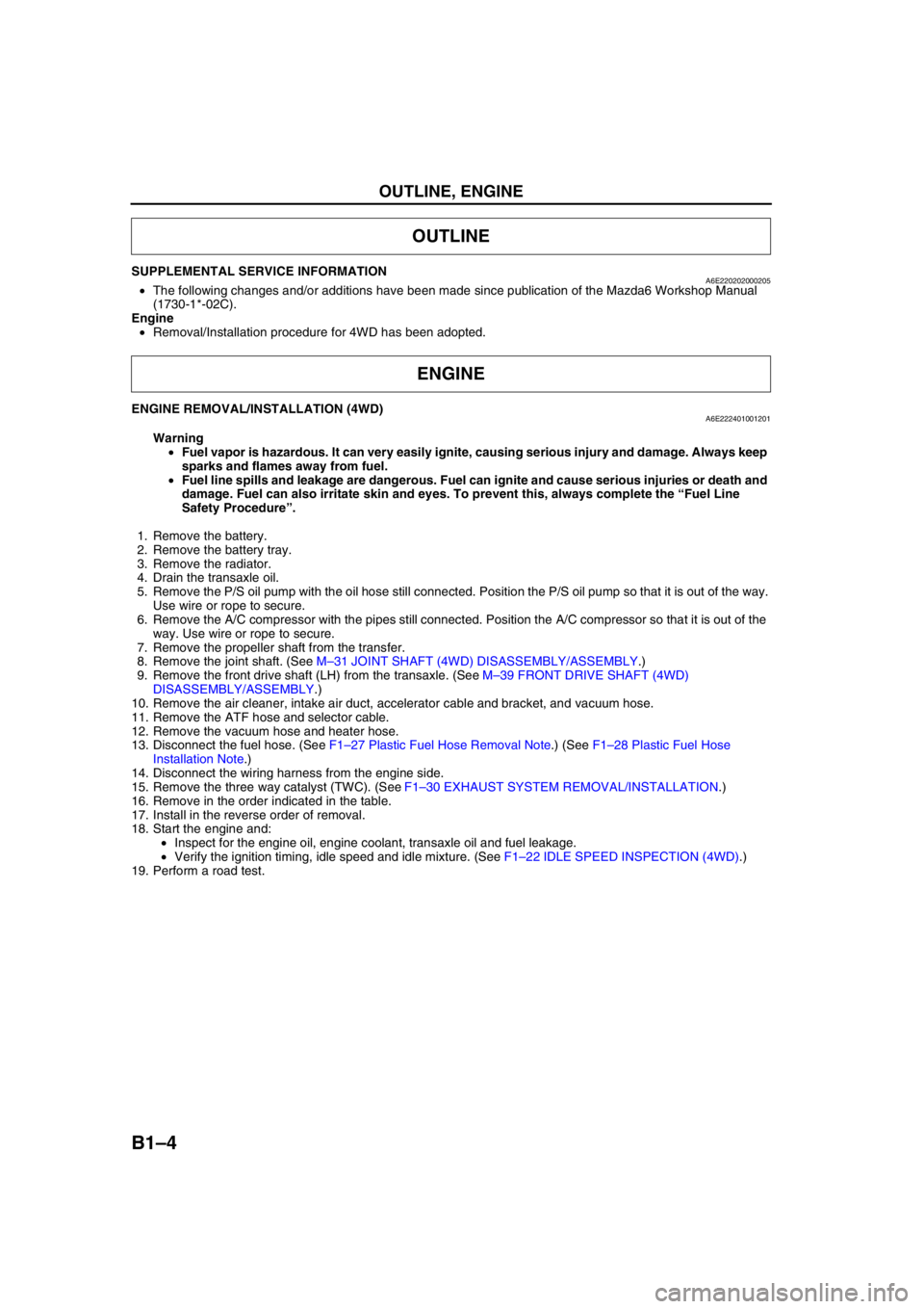
SUPPLEMENTAL SERVICE INFORMATIONA6E220202000205•The following changes and/or additions have been made since publication of the Mazda6 Workshop Manual
(1730-1*-02C).
Engine
•Removal/Installation procedure for 4WD has been adopted.
End Of Sie
ENGINE REMOVAL/INSTALLATION (4WD)A6E222401001201
Warning
•Fuel vapor is hazardous. It can very easily ignite, causing serious injury and damage. Always keep
sparks and flames away from fuel.
•Fuel line spills and leakage are dangerous. Fuel can ignite and cause serious injuries or death and
damage. Fuel can also irritate skin and eyes. To prevent this, always complete the “Fuel Line
Safety Procedure”.
1. Remove the battery.
2. Remove the battery tray.
3. Remove the radiator.
4. Drain the transaxle oil.
5. Remove the P/S oil pump with the oil hose still connected. Position the P/S oil pump so that it is out of the way.
Use wire or rope to secure.
6. Remove the A/C compressor with the pipes still connected. Position the A/C compressor so that it is out of the
way. Use wire or rope to secure.
7. Remove the propeller shaft from the transfer.
8. Remove the joint shaft. (See M–31 JOINT SHAFT (4WD) DISASSEMBLY/ASSEMBLY.)
9. Remove the front drive shaft (LH) from the transaxle. (See M–39 FRONT DRIVE SHAFT (4WD)
DISASSEMBLY/ASSEMBLY.)
10. Remove the air cleaner, intake air duct, accelerator cable and bracket, and vacuum hose.
11. Remove the ATF hose and selector cable.
12. Remove the vacuum hose and heater hose.
13. Disconnect the fuel hose. (See F1–27 Plastic Fuel Hose Removal Note.) (See F1–28 Plastic Fuel Hose
Installation Note.)
14. Disconnect the wiring harness from the engine side.
15. Remove the three way catalyst (TWC). (See F1–30 EXHAUST SYSTEM REMOVAL/INSTALLATION.)
16. Remove in the order indicated in the table.
17. Install in the reverse order of removal.
18. Start the engine and:
•Inspect for the engine oil, engine coolant, transaxle oil and fuel leakage.
•Verify the ignition timing, idle speed and idle mixture. (See F1–22 IDLE SPEED INSPECTION (4WD).)
19. Perform a road test.
OUTLINE
ENGINE