check engine light MAZDA 6 2002 Workshop Manual Suplement
[x] Cancel search | Manufacturer: MAZDA, Model Year: 2002, Model line: 6, Model: MAZDA 6 2002Pages: 909, PDF Size: 17.16 MB
Page 13 of 909

GI–10
SCHEDULED MAINTENANCE
For Israel
Chart symbols:
I : Inspect and clean, repair, adjust, or replace if necessary.
R:Replace
C : Clean
Remarks:
•To ensure efficient operation of the engine and all systems related to emission control, the ignition and fuel systems must
be serviced regularly. It is strongly recommended that all servicing related to these systems be done by an authorized
Mazda Dealer.
•After the described period, continue to follow the described maintenance at the recommended intervals.
•Refer below for a description of items marked* in the maintenance chart.
*1: If the vehicle is operated under any of the following conditions, change the engine oil and oil filter every 10,000 km
(6,000 miles) or shorter.
a. Driving in dusty conditions.
b. Extended periods of idling or low speed operation.
c. Driving for long period in cold temperatures or driving regularly at short distance only.
*2: Also inspect and adjust the power steering and air conditioner drive belts, if installed.
*3: If the brakes are used extensively (for example, continuous hard driving or mountain driving) or if the vehicle is
operated in extremely humid climates, change the brake fluid annually.
*4: If the vehicle is operated in very dusty or sandy areas, clean and if necessary, replace the air cleaner element more
often than the recommended intervals.
*5: This is a full function check of electrical systems such as lights, wiper and washer systems (including wiper blades),
and power windows.
Maintenance ItemMaintenance Interval (Number of months or km (miles), whichever comes first)
Months 12 24 36 48 60 72 84 96 108 120 132 144
×1000 km 15 30 45 60 75 90 105 120 135 150 165 180
×1000 miles 9 18 27 36 45 54 63 72 81 90 99 108
ENGINE
Drive belts *2IIIIIIIIIII I
Engine oil *1RRRRRRRRRRR R
Engine oil filter *1RRRRRRRRRRR R
COOLING SYSTEM
Cooling system
(Including coolant level adjustment)IIIII I
Engine coolantReplace at first 4 years or 90,000 km (54,000 miles);
after that, every 2 years
FUEL SYSTEM
Air cleaner element *4CCCRCCCRCCC R
Fuel filter R R
Fuel lines & hoses IIIII I
IGNITION SYSTEM
Spark plugs Replace every 90,000 km (54,000 miles)
EMISSION CONTROL SYSTEM
Evaporative system I I I
E.G.R. system (if installed) I I I
ELECTRICAL SYSTEM
Battery electrolyte level & specific gravity I I I I I I I I I I I I
All electrical system *5IIIIIIIIIII I
CHASSIS & BODY
Brake & clutch pedals IIIIIIIIIII I
Brake lines, hoses & connections I I I I I I I I I I I I
Brake fluid *3IRIRIRIRIRI R
Parking brake IIIIIIIIIII I
Power brake unit & hoses IIIIIIIIIII I
Disc brakes IIIIIIIIIII I
Power steering fluid, lines, hoses, and
connectionsIIIIIIIIIII I
Page 14 of 909

SCHEDULED MAINTENANCE
GI–11
GI
For GCC
Chart symbols:
I : Inspect and clean, repair, adjust, or replace if necessary.
R : Replace
T:Tighten
C : Clean
Remarks:
End Of Sie
Steering operation & linkages IIIII I
Manual transaxle oil R R
Automatic transaxle fluid level IIIII I
Front & rear suspension & ball joints IIIII
Driveshaft dust boots IIIII
Exhaust system & heat shields IIIII I
Bolts & nuts on seats IIIII I
Body condition (for rust, corrosion & perforation) Inspect annually
Cabin air filter (if installed) R R R R R R R R R R R RMaintenance ItemMaintenance Interval (Number of months or km (miles), whichever comes first)
Months 12 24 36 48 60 72 84 96 108 120 132 144
×1000 km 15 30 45 60 75 90 105 120 135 150 165 180
×1000 miles 9 18 27 36 45 54 63 72 81 90 99 108
•To ensure efficient operation of the engine and all systems related to emission control, the ignition and fuel systems must
be serviced regularly. It is strongly recommended that all servicing related to these systems be done by an authorized
Mazda Dealer.
•After the described period, continue to follow the described maintenance at the recommended intervals.
•Refer below for a description of items marked* in the maintenance chart.
*1: If the vehicle is operated under any of the following conditions, change the engine oil and oil filter more often than
recommended intervals.
a. Driving in dusty conditions.
b. Extended periods of idling or low speed operation.
c. Driving for long period in cold temperatures or driving regularly at short distance only.
*2: Also inspect and adjust the power steering and air conditioner drive belts, if installed.
*3: If the brakes are used extensively (for example, continuous hard driving or mountain driving) or if the vehicle is
operated in extremely humid climates, change the brake fluid annually.
*4: If the vehicle is operated in very dusty or sandy areas, clean and if necessary, replace the air cleaner element more
often than the recommended intervals.
*5: This is a full function check of electrical systems such as lights, wiper and washer systems (including wiper blades),
and power windows.
*6: If the vehicle is operated under any of the following conditions, change the rear differential oil
every 45,000 km (27,000 miles).
a. Towing a trailer or using a car - top carrier
b. Driving in dusty, sandy or wet condition
c. Extended periods of idling or low speed operation
d. Repeated short trips of less than 16 km (10 miles)
*7: If this component has been submerged in water, the oil should be changed.
Maintenance ItemMaintenance Interval (Number of months or km (miles), whichever comes first)
Months 6 121824303642485460667278849096
×1000 km
10 20 30 40 50 60 70 80 90 100 110 120 130 140 150 160
×1000 miles6.25 12.5 18.75 25 31.25 37.5 43.75 50 56.25 62.5 68.75 75 81.25 87.5 93.75 100
ENGINE
Engine valve clearance (leaded fuel) I I I I
Drive belts *2IIIIIIIIIIIIIIII
Engine oil *1RRRRRRRRRRRRRRRR
Engine oil filter *1RRRRRRRRRRRRRRRR
COOLING SYSTEM
Cooling system IIIIIIII
Engine coolant Replace every 2 years
Page 17 of 909

SCHEDULED MAINTENANCE
GI–13
GI
For Israel
Applied VIN (assumed):
JMZ GG1235✻
✻✻ ✻
# 202316-, JMZ GG1435✻
✻✻ ✻
# 202316-, JMZ GY19F2✻
✻✻ ✻
# 146118-, JMZ GY19F5✻
✻✻ ✻
# 146118-
Chart symbols:
I : Inspect and clean, repair, adjust, or replace if necessary.
R : Replace
C : Clean
Remarks:
Engine oil *1 R R R R R R R R R
Engine oil filter *1RRRRRRRRR
Drive belts *2 I I I
Cooling system (including coolant level adjustment) I I I I
Engine coolantReplace at first 4 years or 100,000 km (62,500 miles);
after that, every 2 years
Fuel lines and hoses I I I I
Battery electrolyte level and specific gravity IIIIIIIII
Brake fluid *3 R R R R
Brake lines, hoses and connections IIIIIIIII
Parking brake IIIIIIIII
Power brake unit and hoses IIIIIIIII
Disc brakes IIIIIIIII
Power steering fluid, lines, hoses, and connections IIIIIIIII
Steering operation and linkages I I I I
Manual transaxle oil R
Automatic transaxle fluid level I I I
Rear differential oil (for 4WD)
*7*8
Transfer oil (for 4WD)
*8
Front and rear suspension and ball joints I I I I
Driveshaft dust boots I I I I
Exhaust system and heat shields I I
Cabin air filter (if installed) (pollen filter) R R R R
Body condition
(for rust, corrosion and perforation)Inspect annually
Tires (including spare tyre)
(with inflation pressure adjustment)IIIIIIIII Maintenance ItemMaintenance Interval (Number of months or km (miles), whichever comes first)
Months 12 24 36 48 60 72 84 96 108
×1000 km 20 40 60 80 100 120 140 160 180
×1000 miles 12.5 25 37.5 50 62.5 75 87.5 100 112.5
•The ignition and fuel systems are highly important to the emission control system and to efficient engine operation. All
inspections and adjustments must be made by an Authorized Mazda Dealer.
•After the prescribed period, continue to follow the described maintenance at the recommended intervals.
•Refer below for a description of items marked* in the maintenance chart.
*1: If the vehicle is operated under any of the following conditions, change the engine oil and oil filter every 10,000 km
(6,250 miles) or shorter.
a. Driving in dusty conditions.
b. Extended periods of idling or low speed operation.
c. Driving for long period in cold temperatures or driving regularly at short distance only.
*2: Also inspect and adjust the power steering and air conditioner drive belts, if installed.
*3: If the brakes are used extensively (for example, continuous hard driving or mountain driving) or if the vehicle is
operated in extremely humid climates, change the brake fluid annually.
*4: If the vehicle is operated in very dusty or sandy areas, clean and if necessary, replace the air cleaner element more
often than the recommended intervals.
*5: This is a full function check of electrical systems such as lights, wiper and washer systems (including wiper blades),
and power windows.
Page 19 of 909

SCHEDULED MAINTENANCE
GI–15
GI
For GCC
Applied VIN (assumed):
JM7 GG323✻✻
✻✻✻✻ ✻✻
# 128767-, JM7 GG423✻✻
✻✻✻✻ ✻✻
# 128767-, JM7 GG343✻✻
✻✻✻✻ ✻✻
# 128767-
JM7 GG443✻✻
✻✻✻✻ ✻✻
# 128767-, JM7 GG32F✻✻
✻✻✻✻ ✻✻
# 128767-, JM7 GG42F✻✻
✻✻✻✻ ✻✻
# 128767-
JM7 GG34F✻
✻✻ ✻✻
✻✻ ✻
# 128767-, JM7 GG44F✻
✻✻ ✻✻
✻✻ ✻
# 128767-, JM7 GY49F✻✻
✻✻✻✻ ✻✻
# 101432-
JM7 GY39F✻✻
✻✻✻✻ ✻✻
# 101432-, JM7 GY49F✻
✻✻ ✻
0# 101432-, JM7 GY39F✻
✻✻ ✻
0# 101432-
Chart symbols:
I : Inspect and clean, repair, adjust, or replace if necessary.
R : Replace
T:Tighten
C : Clean
Remarks:
•The ignition and fuel systems are highly important to the emission control system and to efficient engine operation. All
inspections and adjustments must be made by an Authorized Mazda Dealer.
•After the prescribed period, continue to follow the described maintenance at the recommended intervals.
•Refer below for a description of items marked* in the maintenance chart.
*1: If the vehicle is operated under any of the following conditions, change the engine oil and oil filter more often than
recommended intervals.
a. Driving in dusty conditions.
b. Extended periods of idling or low speed operation.
c. Driving for long period in cold temperatures or driving regularly at short distance only.
*2: Also inspect and adjust the power steering and air conditioner drive belts, if installed.
*3: If the brakes are used extensively (for example, continuous hard driving or mountain driving) or if the vehicle is
operated in extremely humid climates, change the brake fluid annually.
*4: If the vehicle is operated in very dusty or sandy areas, clean and if necessary, replace the air cleaner element more
often than the recommended intervals.
*5: This is a full function check of electrical systems such as lights, wiper and washer systems (including wiper blades),
and power windows.
*6: If the vehicle is operated under any of the following conditions, change the rear differential oil
every 45,000 km (27,000 miles).
a. Towing a trailer or using a car - top carrier
b. Driving in dusty, sandy or wet condition
c. Extended periods of idling or low speed operation
d. Repeated short trips of less than 16 km (10 miles)
*7: If this component has been submerged in water, the oil should be changed.
Maintenance ItemMaintenance Interval (Number of months or km (miles), whichever comes first)
Months 6 121824303642485460667278849096
×1000 km
10 20 30 40 50 60 70 80 90 100 110 120 130 140 150 160
×1000 miles6.25 12.5 18.75 25 31.25 37.5 43.75 50 56.25 62.5 68.75 75 81.25 87.5 93.75 100
ENGINE
Engine valve clearance Unleaded fuel Audible inspect every 120,000 km (75,000 miles), if noisy, adjust
leaded fuel I I I I
Drive belts *2IIIIIIIIIIIIIIII
Engine oil *1RRRRRRRRRRRRRRRR
Engine oil filter *1RRRRRRRRRRRRRRRR
COOLING SYSTEM
Cooling system IIIIIIII
Engine coolant Replace every 2 years
FUEL SYSTEM
Air cleaner element *4CCRCCRCC
Fuel filter R R R R
Fuel lines and hoses IIIIIIII
IGNITION SYSTEM
Spark plugs Unleaded fuel Replace every 100,000 km (62,500 miles)
Leaded fuel IIIIIIII
EMISSION CONTROL SYSTEM
Idle mixture (leaded fuel) IIIIIIII
Page 116 of 909
F1–28
FUEL SYSTEM
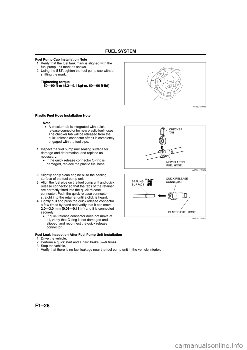
Fuel Pump Cap Installation Note
1. Verify that the fuel tank mark is aligned with the
fuel pump unit mark as shown.
2. Using the SST, tighten the fuel pump cap without
shifting the mark.
Tightening torque
80—90 N·m {8.2—9.1 kgf·m, 60—66 ft·lbf}
Plastic Fuel Hose Installation Note
Note
•A checker tab is integrated with quick
release connector for new plastic fuel hoses.
The checker tab will be released from the
quick release connector after it is completely
engaged with the fuel pipe.
1. Inspect the fuel pump unit sealing surface for
damage and deformation, and replace as
necessary.
•If the quick release connector O-ring is
damaged, replace the plastic fuel hose.
2. Slightly apply clean engine oil to the sealing
surface of the fuel pump unit.
3. Align the fuel pipe on the fuel pump unit and quick
release connector so that the tabs of the retainer
are correctly fitted into the quick release
connector. Push the quick release connector
straight into the retainer until a click is heard.
4. Lightly pull and push the quick release connector
a few times by hand and verify that it can move
2.0—3.0 mm {0.08—0.11 in} and it is connected
securely.
•If quick release connector does not move at
all, verify that O-ring is not damaged and
slipped, and reconnect the quick release
connector.
Fuel Leak Inspection After Fuel Pump Unit Installation
1. Drive the vehicle.
2. Perform a quick start and a hard brake 5—6 times.
3. Stop the vehicle.
4. Verify that there is no fuel leakage near the fuel pump unit in the vehicle interior.
End Of Sie
A6E39122013
CHECKER
TA B
NEW PLASTIC
FUEL HOSE
A6E3912W004
OILOIL
PLASTIC FUEL HOSE QUICK RELEASE
CONNECTOR SEALING
SURFACE
A6E3912W006
Page 190 of 909
F2–38
INTAKE-AIR SYSTEM
TURBOCHARGER INSPECTIONA6E401013700201
Note
•If the following problems exist, diagnosis the turbocharger using the following symptom troubleshooting
procedures.
1. Lack of power: perform “NO.12 LACK/LOSS OF POWER”. (See F2–195 NO.12 LACK/LOSS OF POWER-
ACCELERATION/CRUISE.)
2. Oil leak: perform “NO.16 HIGH OIL CONSUMPTION/LEAKAGE”. (See F2–209 NO.16 HIGH OIL
CONSUMPTION/LEAKAGE.)
3. Noise: perform “NO. 21 ENGINE NOISE”. (See F2–217 NO.21 ENGINE NOISE.)
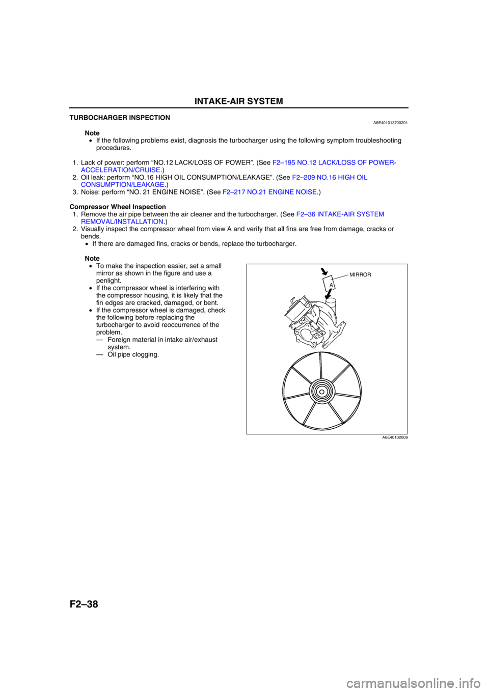
Compressor Wheel Inspection
1. Remove the air pipe between the air cleaner and the turbocharger. (See F2–36 INTAKE-AIR SYSTEM
REMOVAL/INSTALLATION.)
2. Visually inspect the compressor wheel from view A and verify that all fins are free from damage, cracks or
bends.
•If there are damaged fins, cracks or bends, replace the turbocharger.
Note
•To make the inspection easier, set a small
mirror as shown in the figure and use a
penlight.
•If the compressor wheel is interfering with
the compressor housing, it is likely that the
fin edges are cracked, damaged, or bent.
•If the compressor wheel is damaged, check
the following before replacing the
turbocharger to avoid reoccurrence of the
problem.
—Foreign material in intake air/exhaust
system.
—Oil pipe clogging.
MIRROR
A
A6E40102009
Page 201 of 909
FUEL SYSTEM
F2–49
F2
(2) Apply a slight amount of clean engine oil to
the sealing surface of the fuel pump unit.
(3) Align the fuel pipe on the fuel pump unit and
quick release connector so that the tabs of the
retainer are correctly fitted into the quick
release connector. Push the quick release
connector straight into the retainer until a click
is heard.
(4) Lightly pull and push the quick release
connector a few times by hand and verify that
it can move 2.0—3.0 mm {0.08—0.11 in} and
it is connected securely.
•If the quick release connector does not
move at all, verify that O-ring is not
damaged of that is has not slipped, and reconnect the quick release connector.
2. When the retainer is removed, perform the following procedure.
End Of Sie
FUEL TANK INSPECTIONA6E401242110202
Caution
•Disconnecting/connecting the quick release connector without cleaning it may possibly cause
damage to the fuel pipe and quick release connector. Always clean the quick release connector
joint area before disconnecting/connecting using a cloth or soft brush, and make sure that it is
free of foreign material.
Note
•This inspection is for two rollover valves and check valve (two-way) integrated in the fuel tank.
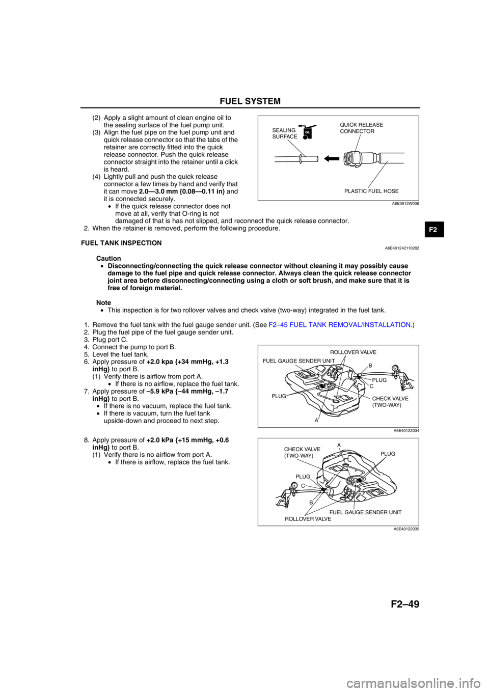
1. Remove the fuel tank with the fuel gauge sender unit. (See F2–45 FUEL TANK REMOVAL/INSTALLATION.)
2. Plug the fuel pipe of the fuel gauge sender unit.
3. Plug port C.
4. Connect the pump to port B.
5. Level the fuel tank.
6. Apply pressure of +2.0 kpa {+34 mmHg, +1.3
inHg} to port B.
(1) Verify there is airflow from port A.
•If there is no airflow, replace the fuel tank.
7. Apply pressure of –5.9 kPa {–44 mmHg, –1.7
inHg} to port B.
•If there is no vacuum, replace the fuel tank.
•If there is vacuum, turn the fuel tank
upside-down and proceed to next step.
8. Apply pressure of +2.0 kPa {+15 mmHg, +0.6
inHg} to port B.
(1) Verify there is no airflow from port A.
•If there is airflow, replace the fuel tank.
End Of Sie
OILOIL
PLASTIC FUEL HOSE QUICK RELEASE
CONNECTOR SEALING
SURFACE
A6E3912W006
B
C
APLUG
PLUG
CHECK VALVE
(TWO-WAY)
FUEL GAUGE SENDER UNIT
ROLLOVER VALVE
A6E40122034
B CA
PLUGPLUG
CHECK VALVE
(TWO-WAY)
FUEL GAUGE SENDER UNIT
ROLLOVER VALVE
A6E40122035
Page 380 of 909
F2–228
TROUBLESHOOTING
Inspection Method for Sensors
1. Connect the WDS or equivalent to the DLC-2.
2. Turn the engine switch to ON (Engine OFF).
Note
•If the engine starts and runs, perform the following steps at idle.
3. Access PIDs for the switch you are inspecting.
4. Vibrate the sensor slightly with your finger.
•If the PID value is unstable or malfunction occurs, check for poor connection and/or poorly mounted
sensor.
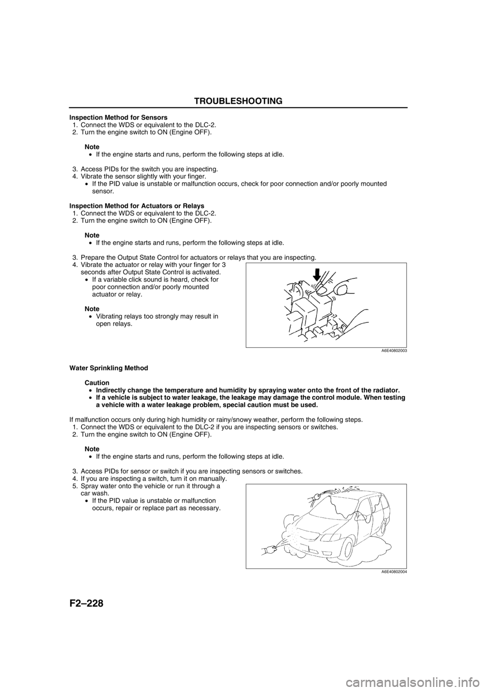
Inspection Method for Actuators or Relays
1. Connect the WDS or equivalent to the DLC-2.
2. Turn the engine switch to ON (Engine OFF).
Note
•If the engine starts and runs, perform the following steps at idle.
3. Prepare the Output State Control for actuators or relays that you are inspecting.
4. Vibrate the actuator or relay with your finger for 3
seconds after Output State Control is activated.
•If a variable click sound is heard, check for
poor connection and/or poorly mounted
actuator or relay.
Note
•Vibrating relays too strongly may result in
open relays.
Water Sprinkling Method
Caution
•Indirectly change the temperature and humidity by spraying water onto the front of the radiator.
•If a vehicle is subject to water leakage, the leakage may damage the control module. When testing
a vehicle with a water leakage problem, special caution must be used.
If malfunction occurs only during high humidity or rainy/snowy weather, perform the following steps.
1. Connect the WDS or equivalent to the DLC-2 if you are inspecting sensors or switches.
2. Turn the engine switch to ON (Engine OFF).
Note
•If the engine starts and runs, perform the following steps at idle.
3. Access PIDs for sensor or switch if you are inspecting sensors or switches.
4. If you are inspecting a switch, turn it on manually.
5. Spray water onto the vehicle or run it through a
car wash.
•If the PID value is unstable or malfunction
occurs, repair or replace part as necessary.
End Of Sie
A6E40802003
A6E40802004
Page 547 of 909
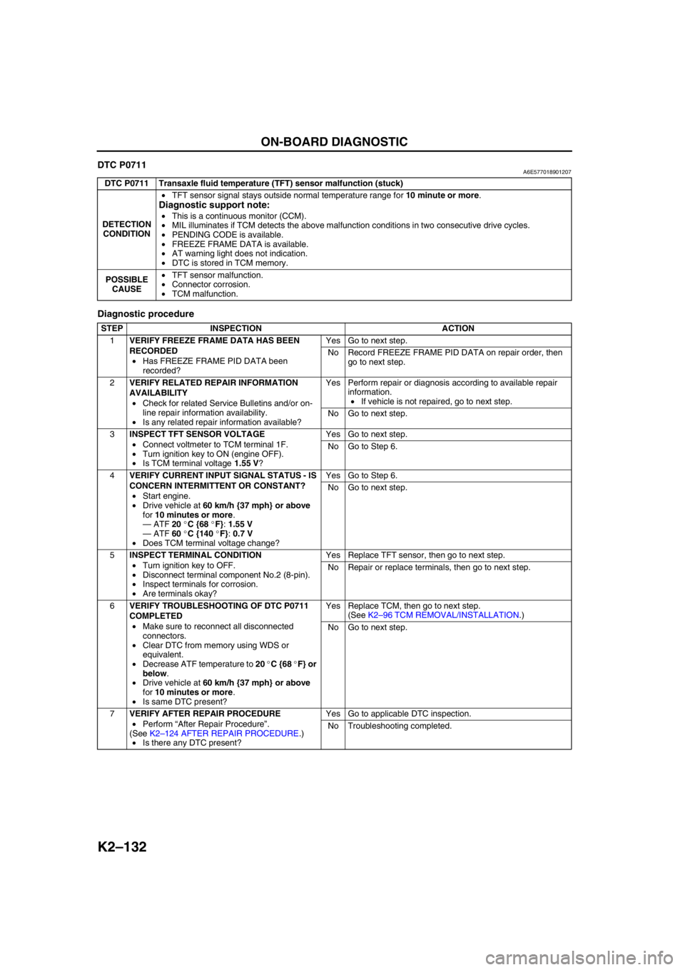
K2–132
ON-BOARD DIAGNOSTIC
DTC P0711A6E577018901207
Diagnostic procedure
End Of Sie
DTC P0711 Transaxle fluid temperature (TFT) sensor malfunction (stuck)
DETECTION
CONDITION•TFT sensor signal stays outside normal temperature range for 10 minute or more.
Diagnostic support note:
•This is a continuous monitor (CCM).
•MIL illuminates if TCM detects the above malfunction conditions in two consecutive drive cycles.
•PENDING CODE is available.
•FREEZE FRAME DATA is available.
•AT warning light does not indication.
•DTC is stored in TCM memory.
POSSIBLE
CAUSE•TFT sensor malfunction.
•Connector corrosion.
•TCM malfunction.
STEP INSPECTION ACTION
1VERIFY FREEZE FRAME DATA HAS BEEN
RECORDED
•Has FREEZE FRAME PID DATA been
recorded?Yes Go to next step.
No Record FREEZE FRAME PID DATA on repair order, then
go to next step.
2VERIFY RELATED REPAIR INFORMATION
AVAILABILITY
•Check for related Service Bulletins and/or on-
line repair information availability.
•Is any related repair information available?Yes Perform repair or diagnosis according to available repair
information.
•If vehicle is not repaired, go to next step.
No Go to next step.
3INSPECT TFT SENSOR VOLTAGE
•Connect voltmeter to TCM terminal 1F.
•Turn ignition key to ON (engine OFF).
•Is TCM terminal voltage 1.55 V?Yes Go to next step.
No Go to Step 6.
4VERIFY CURRENT INPUT SIGNAL STATUS - IS
CONCERN INTERMITTENT OR CONSTANT?
•Start engine.
•Drive vehicle at 60 km/h {37 mph} or above
for 10 minutes or more.
—ATF 20 °C {68 °F}: 1.55 V
—ATF 60 °C {140 °F}: 0.7 V
•Does TCM terminal voltage change?Yes Go to Step 6.
No Go to next step.
5INSPECT TERMINAL CONDITION
•Turn ignition key to OFF.
•Disconnect terminal component No.2 (8-pin).
•Inspect terminals for corrosion.
•Are terminals okay?Yes Replace TFT sensor, then go to next step.
No Repair or replace terminals, then go to next step.
6VERIFY TROUBLESHOOTING OF DTC P0711
COMPLETED
•Make sure to reconnect all disconnected
connectors.
•Clear DTC from memory using WDS or
equivalent.
•Decrease ATF temperature to 20 °C {68 °F} or
below.
•Drive vehicle at 60 km/h {37 mph} or above
for 10 minutes or more.
•Is same DTC present?Yes Replace TCM, then go to next step.
(See K2–96 TCM REMOVAL/INSTALLATION.)
No Go to next step.
7VERIFY AFTER REPAIR PROCEDURE
•Perform “After Repair Procedure”.
(See K2–124 AFTER REPAIR PROCEDURE.)
•Is there any DTC present?Yes Go to applicable DTC inspection.
No Troubleshooting completed.
Page 548 of 909
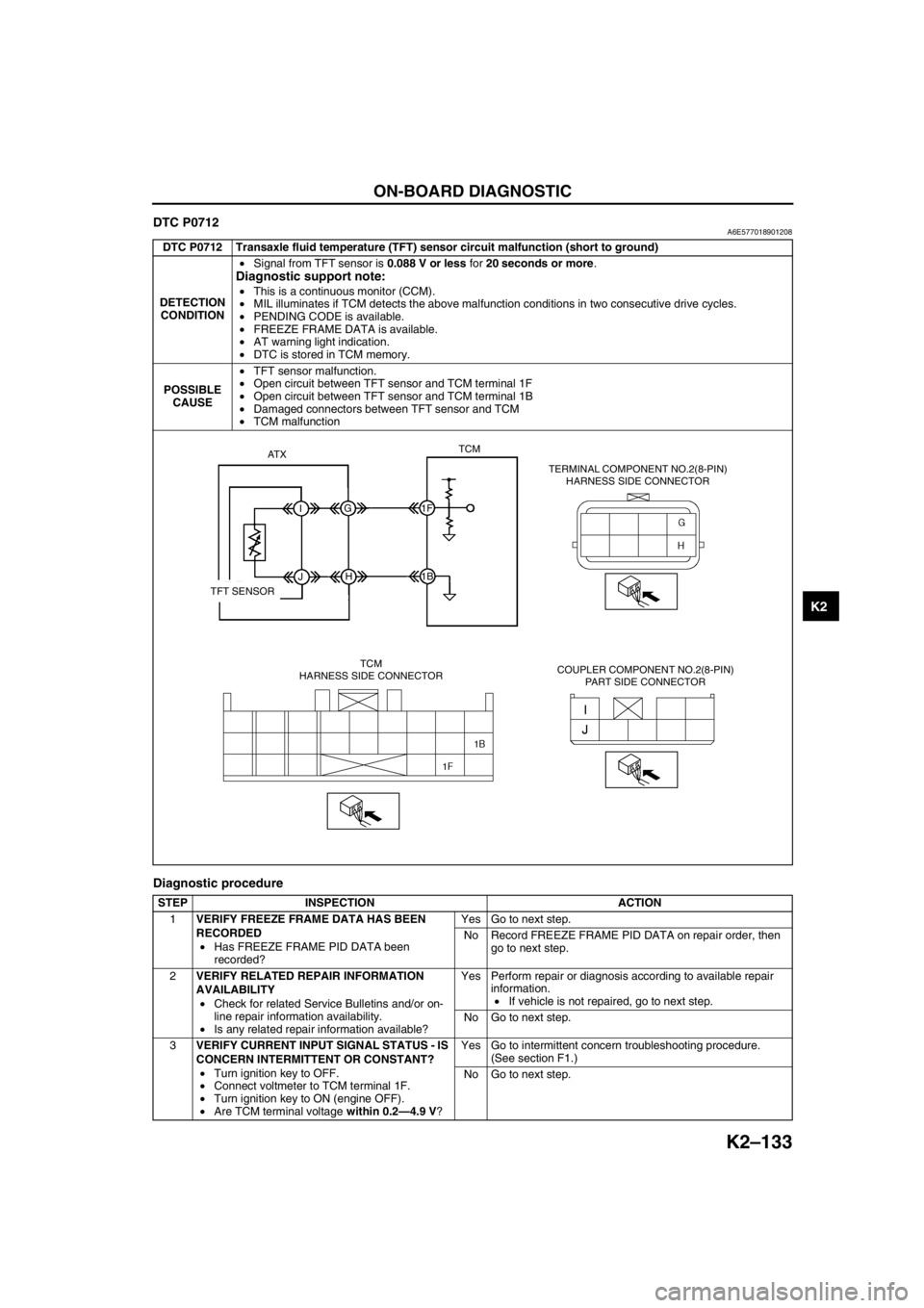
ON-BOARD DIAGNOSTIC
K2–133
K2
DTC P0712A6E577018901208
Diagnostic procedure
DTC P0712 Transaxle fluid temperature (TFT) sensor circuit malfunction (short to ground)
DETECTION
CONDITION•Signal from TFT sensor is 0.088 V or less for 20 seconds or more.
Diagnostic support note:
•This is a continuous monitor (CCM).
•MIL illuminates if TCM detects the above malfunction conditions in two consecutive drive cycles.
•PENDING CODE is available.
•FREEZE FRAME DATA is available.
•AT warning light indication.
•DTC is stored in TCM memory.
POSSIBLE
CAUSE•TFT sensor malfunction.
•Open circuit between TFT sensor and TCM terminal 1F
•Open circuit between TFT sensor and TCM terminal 1B
•Damaged connectors between TFT sensor and TCM
•TCM malfunction
STEP INSPECTION ACTION
1VERIFY FREEZE FRAME DATA HAS BEEN
RECORDED
•Has FREEZE FRAME PID DATA been
recorded?Yes Go to next step.
No Record FREEZE FRAME PID DATA on repair order, then
go to next step.
2VERIFY RELATED REPAIR INFORMATION
AVAILABILITY
•Check for related Service Bulletins and/or on-
line repair information availability.
•Is any related repair information available?Yes Perform repair or diagnosis according to available repair
information.
•If vehicle is not repaired, go to next step.
No Go to next step.
3VERIFY CURRENT INPUT SIGNAL STATUS - IS
CONCERN INTERMITTENT OR CONSTANT?
•Turn ignition key to OFF.
•Connect voltmeter to TCM terminal 1F.
•Turn ignition key to ON (engine OFF).
•Are TCM terminal voltage within 0.2—4.9 V?Yes Go to intermittent concern troubleshooting procedure.
(See section F1.)
No Go to next step.
AT XTCM
IG1F
1B
JH
TFT SENSOR
TCM
HARNESS SIDE CONNECTORTERMINAL COMPONENT NO.2(8-PIN)
HARNESS SIDE CONNECTOR
COUPLER COMPONENT NO.2(8-PIN)
PART SIDE CONNECTOR