oil type MAZDA 6 2002 Workshop Manual Suplement
[x] Cancel search | Manufacturer: MAZDA, Model Year: 2002, Model line: 6, Model: MAZDA 6 2002Pages: 909, PDF Size: 17.16 MB
Page 33 of 909

B2–2
OUTLINE
OUTLINE OF CONSTRUCTIONA6E230202000201•MZR-CD (RF Turbo) engine is newly adopted as Mazda6 (GG, GY).
•The construction of MZR-CD (RF Turbo) engine and operation which were newly adopted for the Mazda6 (GG,
GY) are the same as the current Mazda MPV(LW) MZR-CD (RF Turbo) engine model and current Mazda 323
(BJ) RF Turbo engine model except for the following components. (See Mazda MPV Workshop Manual
Supplement 1737-1*-02C.), (See Mazda 323 Workshop Manual Supplement 1633-10-98G.)
—Engine mount
•The construction and the operation of the engine mount for the new Mazda6 (GG, GY) MZR-CD (RF Turbo)
engine model is the same as the current Mazda6 (GG). (See Mazda6 Training Manual 3359-1*-02C)
End Of Sie
FEATURESA6E230202000202Improved engine performance
•Coated pistons have been adopted.
Reduced engine noise and vibration
•An aluminium alloy oil pan upper block has been adopted.
•An eight counter weight crankshaft has been adopted.
•A crankshaft pulley cover has been adopted.
•An engine cover with insulator has been adopted.
•A pendulum type engine mount has been adopted.
Improved serviceability
•A serpentine type drive belt has been adopted.
•An auto tensioner that automatically adjusts the drive belt tension has been adopted.
Improved design
•An engine cover has been adopted.
End Of Sie
SPECIFICATIONSA6E230202000203
End Of Sie
OUTLINE
ItemSpecifications
New Mazda6 (GG, GY) Current Mazda MPV (LW)
MZR-CD (RF Turbo) MZR-CD (RF Turbo)
TypeDiesel, 4-cycle
Cylinder arrangement and number In-line, 4-cylinder
Combustion chamber Direct injection
Valve system SOHC, belt-driven, 16-valve
Displacement (ml {cc, cu in}) 1,998 {1.998, 122.9}
Bore × stroke (mm {in}) 86.0 × 86.0 {3.39 × 3.39}
Compression ratio 18.4
Compression pressure
(kPa {kgf/cm
2, psi} [rpm])3,500 {35.7, 507.7} [250]
Valve timingINOpen BTDC (°)6
Close ABDC (°)30
EXOpen BBDC (°)41
Close ATDC (°)8
Valve clearance
[engine cold]IN (mm {in}) 0.12 —0.18 {0.005—0.007} (0.15±0.03 {0.006±0.0011})
EX (mm {in}) 0.32—0.38 {0.013—0.014} (0.35±0.03 {0.014±0.0011})
Page 66 of 909

D–2
OUTLINE
OUTLINE OF CONSTRUCTIONA6E330202000201•The construction and the operation of the oil cooler and the oil filter for the new Mazda6 (GG, GY) MZR-CD (RF
Turbo) engine model is the same as the current Mazda MPV (LW) MZR-CD (RF Turbo) engine model. (See
Mazda MPV Workshop Manual Supplement 1737-1*-02D.)
•The construction and the operation of the lubrication system except for the oil cooler and oil filter for the new
Mazda6 (GG, GY) MZR-CD (RF Turbo) engine model is the same as the current Mazda 626, 626 Station
Wagon (GF, GW) RF Turbo engine model. (European specs.) (See Mazda 626, 626 Station Wagon RF Turbo
Workshop Manual Supplement 1614-10-98D.)
•The construction and the operation of the lubrication system for the new Mazda6 (GG, GY) L8, LF, and L3
engine models is the same as the current Mazda6 (GG) engine model L8, LF, and L3 engine models. (See
Mazda6 Training Manual 3359-1*-02C, Mazda6 Workshop Manual 1730-1*-02C.)
End Of Sie
SPECIFICATIONSA6E330202000202Gasoline engine
* : Always verify the oil level with the dipsticks since the engine oil capacity differs according to dipstick
specifications. (See Mazda6 Workshop Manual 1730-1*-02C Section D.)
Recommended Engine Oil (Gasoline Engine)
•The maintenance intervals on the scheduled maintenance table (See GI–8 SCHEDULED MAINTENANCE
TABLE) can only be supported with the use of following oils.
OUTLINE
ItemSpecification
New
Mazda6
(GG, GY)Current
Mazda6
(GG)New
Mazda6
(GG, GY)Current
Mazda6
(GG)New
Mazda6
(GG, GY)Current
Mazda6
(GG)
L8 LF L3*
Lubrication system Force-fed type
Oil coolerWater-cooled
Oil pressure
(approximate quantity)
[oil temperature: 100°C
{212°F}](kPa {kgf/cm
2, psi})
min [rpm]234—521
{2.39—5.31, 33.9—75.5}
[3,000]395—649
{4.03—6.61,
57.3—94.1}
[3,000]
Oil pumpType Trochoid gear type
Relief pressure
(approximate
quantity) (kPa {kgf/cm
2,
psi})500—600
{5.09—6.11, 72.6—87.0}
Oil filterType Full-flow, Paper element
Bypass pressure
(approximate
quantity)(kPa kgf/cm
2, psi})80—120
{0.9—1.2, 12.8—17.0}
Oil capacity
(approximate
quantity)Total
(dry engine)(L {US qt, lmp qt}) 4.6 {4.8, 4.0} Dipstick A: 4.2 {4.4, 3.7}
Dipstick B: 5.1 {5.4, 4.5}
Oil replacement (L {US qt, lmp qt}) 3.9 {4.0, 3.4} Dipstick A: 3.1 {3.3, 2.7}
Dipstick B: 4.0 {4.2, 3.5}
Oil and oil filter
replacement(L {US qt, lmp qt}) 4.3 {4.5, 3.8} Dipstick A: 3.5 {3.7, 3.1}
Dipstick B: 4.4 {4.6, 3.9}
ItemSpecification
New Mazda6
(GG, GY), Current Mazda6
(GG)New Mazda6
(GG, GY), Current Mazda6
(GG)
L8, LF, L3
Engine oil GradeAPI SL
ACEA A3
Viscosity (SAE) 5W-30, 10W-40 5W-20
RemarksMazda genuine Dexelia oil e.g. —
Page 67 of 909

OUTLINE
D–3
D
Diesel engine
Bold frames: New specifications
Recommended Engine Oil (Diesel Engine)
•The maintenance intervals on the scheduled maintenance table (See GI–8 SCHEDULED MAINTENANCE
TABLE) can only be supported with the use of following oils.
Bold frames: New specifications
End Of Sie
ItemSpecification
New Mazda6
(GG, GY)Current
Mazda 626, 626
Station Wagon
(GF, GW)Current
Mazda MPV
(LW)
MZR-CD (RF Turbo) RF TurboMZR-CD (RF
Turbo)
Lubrication system Force-fed type—
Oil cooler Water-cooled—
Oil pressure
(approximate quantity)
[oil temperature: 100°C {212°F}](kPa {kgf/cm
2, psi})
min [rpm]147 {1.5, 21} [1,000],
343 {3.5, 50} [3,000]—
Oil pumpType Trochoid gear type—Trochoid gear type
Relief pressure
(approximate
quantity)(kPa {kgf/cm
2, psi})
[rpm]580—700
{5.9—7.1,
84.1—101.5}
[3,000]—580—700
{5.9—7.1,
84.1—101.5}
[3,000]
Oil filterTypeFull-flow,
Paper element—Full-flow,
Paper element
Bypass pressure
(approximate
quantity)(kPa kgf/cm
2, psi})78—118
{0.8—1.2,
11.3—17.1} —78—118
{0.8—1.2,
11.3—17.1}
Oil capacity
(approximate
quantity)Total
(dry engine)(L {US qt, lmp qt}) 5.5 {5.8, 4.8} 5.4 {5.7, 4.8} —
Oil replacement (L {US qt, lmp qt}) 4.8 {5.1, 4.2} 4.5 {4.8, 4.0}—
Oil and oil filter
replacement(L {US qt, lmp qt}) 5.0 {5.3 ,4.4} 4.7 {5.0, 4.1} —
ItemSpecification
New Mazda6
(GG, GY)Current
Mazda 626, 626
Station Wagon
(GF, GW)
MZR-CD (RF Turbo) RF Turbo
Engine oil GradeAPI CF CD, CE, CF-4 CD
ACEA B1 or B3 B3 B3 or B4—
Viscosity (SAE) 5W-30 10W-40 5W-30, 10W-30 5W-30, 10W-30
RemarksMazda genuine
Dexelia oil e.g.——
Page 72 of 909

D–8
ENGINE OIL
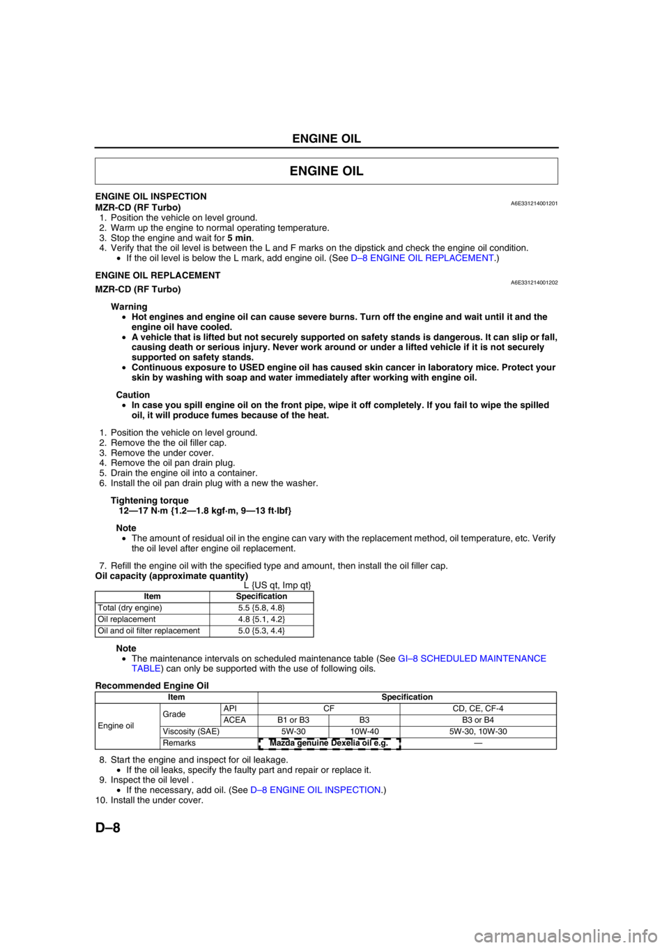
ENGINE OIL INSPECTIONA6E331214001201MZR-CD (RF Turbo)
1. Position the vehicle on level ground.
2. Warm up the engine to normal operating temperature.
3. Stop the engine and wait for 5 min.
4. Verify that the oil level is between the L and F marks on the dipstick and check the engine oil condition.
•If the oil level is below the L mark, add engine oil. (See D–8 ENGINE OIL REPLACEMENT.)
End Of SieENGINE OIL REPLACEMENTA6E331214001202MZR-CD (RF Turbo)
Warning
•Hot engines and engine oil can cause severe burns. Turn off the engine and wait until it and the
engine oil have cooled.
•A vehicle that is lifted but not securely supported on safety stands is dangerous. It can slip or fall,
causing death or serious injury. Never work around or under a lifted vehicle if it is not securely
supported on safety stands.
•Continuous exposure to USED engine oil has caused skin cancer in laboratory mice. Protect your
skin by washing with soap and water immediately after working with engine oil.
Caution
•In case you spill engine oil on the front pipe, wipe it off completely. If you fail to wipe the spilled
oil, it will produce fumes because of the heat.
1. Position the vehicle on level ground.
2. Remove the the oil filler cap.
3. Remove the under cover.
4. Remove the oil pan drain plug.
5. Drain the engine oil into a container.
6. Install the oil pan drain plug with a new the washer.
Tightening torque
12—17 N·m {1.2—1.8 kgf·m, 9—13 ft·lbf}
Note
•The amount of residual oil in the engine can vary with the replacement method, oil temperature, etc. Verify
the oil level after engine oil replacement.
7. Refill the engine oil with the specified type and amount, then install the oil filler cap.
Oil capacity (approximate quantity)
L {US qt, Imp qt}
Note
•The maintenance intervals on scheduled maintenance table (See GI–8 SCHEDULED MAINTENANCE
TABLE) can only be supported with the use of following oils.
Recommended Engine Oil
8. Start the engine and inspect for oil leakage.
•If the oil leaks, specify the faulty part and repair or replace it.
9. Inspect the oil level .
•If the necessary, add oil. (See D–8 ENGINE OIL INSPECTION.)
10. Install the under cover.
End Of Sie
ENGINE OIL
Item Specification
Total (dry engine) 5.5 {5.8, 4.8}
Oil replacement 4.8 {5.1, 4.2}
Oil and oil filter replacement 5.0 {5.3, 4.4}
Item Specification
Engine oil GradeAPI CF CD, CE, CF-4
ACEA B1 or B3 B3 B3 or B4
Viscosity (SAE) 5W-30 10W-40 5W-30, 10W-30
RemarksMazda genuine Dexelia oil e.g. —
Page 74 of 909

D–10
OIL PAN
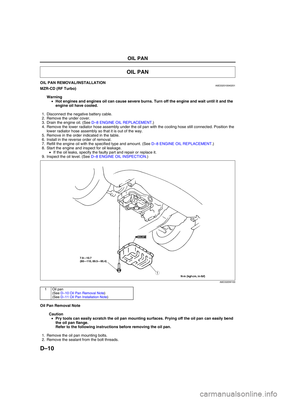
OIL PAN REMOVAL/INSTALLATIONA6E332010040201MZR-CD (RF Turbo)
Warning
•Hot engines and engines oil can cause severe burns. Turn off the engine and wait until it and the
engine oil have cooled.
1. Disconnect the negative battery cable.
2. Remove the under cover.
3. Drain the engine oil. (See D–8 ENGINE OIL REPLACEMENT.)
4. Remove the lower radiator hose assembly under the oil pan with the cooling hose still connected. Position the
lower radiator hose assembly so that it is out of the way.
5. Remove in the order indicated in the table.
6. Install in the reverse order of removal.
7. Refill the engine oil with the specified type and amount. (See D–8 ENGINE OIL REPLACEMENT.)
8. Start the engine and inspect for oil leakage.
•If the oil leaks, specify the faulty part and repair or replace it.
9. Inspect the oil level. (See D–8 ENGINE OIL INSPECTION.)
.
Oil Pan Removal Note
Caution
•Pry tools can easily scratch the oil pan mounting surfaces. Prying off the oil pan can easily bend
the oil pan flange.
Refer to the following instructions before removing the oil pan.
1. Remove the oil pan mounting bolts.
2. Remove the sealant from the bolt threads.
OIL PAN
7.9—10.7
{80—110, 69.5—95.4}
N·m {kgf·cm, in·lbf}
1
SEALANTSEALANT
A6E3320W100
1Oil pan
(See D–10 Oil Pan Removal Note)
(See D–11 Oil Pan Installation Note)
Page 90 of 909

F1–2
OUTLINE
OUTLINE OF CONSTRUCTIONA6E390218881201•The fuel and emission control systems are essentially carried over from the current Mazda6 (GG), except for
the following features. (See Mazda6 Training Manual 3359-1*-02C.)
End Of Sie
FEATURESA6E390218881202System simplification
•Controller area network has been adopted with TCM communication (4WD).
TCM adoption
•DTC for CAN (TCM communication) has been adopted.
Modifications to match the vehicle characteristics
•The idle speed has been modified.
•Fuel pump (transfer) has been adopted.
End Of Sie
SPECIFICATIONSA6E390218881203
*1: Without the BARO sensor
*2: With the BARO sensor
Bold frames: New specifications
End Of Sie
OUTLINE
Item 2WD 4WD
Air cleaner element Type Paper element (oil permeated)
IAC valve Type Duty control
Fuel injectorType Hi-ohmic
Type of fuel delivery Top-feed
Type of drive Voltage
Pressure regulatorRegulating pressure
(kPa {kgf/cm
2, psi})440 {4.5, 64}
Fuel tankCapacity
(L {US qt, lmp qt})64 {68, 56} 62 {65, 54}
Fuel SpecificationUnleaded
(RON 90*
1/95*2 or above)Unleaded (RON 95 or above)
Catalyst Type TWC (monolythic)
EGR control Type Stepping motor type
Evaporative emission control
systemType Canister type
PCV system Type Closed type
Page 127 of 909

CONTROL SYSTEM
F1–39
F1
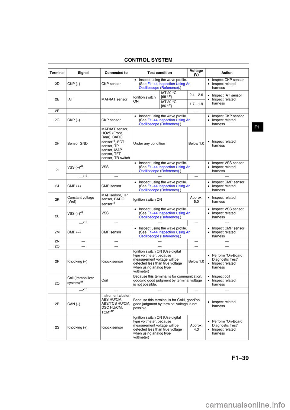
2D CKP (+) CKP sensor•Inspect using the wave profile.
(See F1–44 Inspection Using An
Oscilloscope (Reference).)•Inspect CKP sensor
•Inspect related
harness
2E IAT MAF/IAT sensorIgnition switch
ONIAT 20 °C
{68 °F}2.4—2.6
•Inspect IAT sensor
•Inspect related
harness IAT 30 °C
{86 °F}1.7—1.9
2F—— — ——
2G CKP (–) CKP sensor•Inspect using the wave profile.
(See F1–44 Inspection Using An
Oscilloscope (Reference).)•Inspect CKP sensor
•Inspect related
harness
2H Sensor GNDMAF/IAT sensor,
HO2S (Front,
Rear), BARO
sensor*
6, ECT
sensor, TP
sensor, MAP
sensor, TFT
sensor, TR switchUnder any condition Below 1.0•Inspect related
harness
2IVSS (–)*
8VSS•Inspect using the wave profile.
(See F1–44 Inspection Using An
Oscilloscope (Reference).)•Inspect VSS sensor
•Inspect related
harness
—*
13————
2J CMP (+) CMP sensor•Inspect using the wave profile.
(See F1–44 Inspection Using An
Oscilloscope (Reference).)•Inspect CMP sensor
•Inspect related
harness
2KConstant voltage
(Vref)MAP sensor, TP
sensor, BARO
sensor*
6Ignition switch ONApprox.
5.0•Inspect related
harness
2LVSS (+)*
8VSS•Inspect using the wave profile.
(See F1–44 Inspection Using An
Oscilloscope (Reference).)•Inspect VSS sensor
•Inspect related
harness
—*
13————
2M CMP (–) CMP sensor•Inspect using the wave profile.
(See F1–44 Inspection Using An
Oscilloscope (Reference).)•Inspect CMP sensor
•Inspect related
harness
2N—— — ——
2O—— — ——
2P Knocking (–) Knock sensorIgnition switch ON (Use digital
type voltmeter, because
measurement voltage will be
detected less than true voltage
when using analog type
voltmeter)Below 1.0•Perform “On-Board
Diagnostic Test”
•Inspect related
harness
2QCoil (Immobilizer
system)*
9CoilBecause this terminal is for communication,
good/no good judgment by terminal voltage
is not possible.•Inspect coil
•Inspect related
harness
—*
10————
2R CAN (–)Instrument cluster,
ABS HU/CM,
ABS/TCS HU/CM,
DSC HU/CM,
TCM*
12
Because this terminal is for CAN, good/no
good judgment by terminal voltage is not
possible.•Inspect related
harness
2S Knocking (+) Knock sensorIgnition switch ON (Use digital
type voltmeter, because
measurement voltage will be
detected less than true voltage
when using analog type
voltmeter)Approx.
4.3•Perform “On-Board
Diagnostic Test”
•Inspect related
harness Terminal Signal Connected to Test conditionVoltage
(V)Action
Page 404 of 909

J2–2
OUTLINE
OUTLINE OF CONSTRUCTIONA6E520201025203•The construction and operation of the manual transaxle is the same as those of the current A65M-R type
manual transaxle, except for the following features. (See MPV Workshop Manual supplement 1737-1*-02D.)
End Of Sie
FEATURESA6E520201025201Improved drivability
•The gear ratio has been changed.
End Of Sie
SPECIFICATIONSA6E520201025202
Bold frames:New specifications
End Of Sie
OUTLINE
Item New Mazda6 (GG, GY) Current MPV (LW)
Transaxle typeA65M-R
Transaxle control Floor-shift
Operation system Cable
Shift assistForward
Synchromesh
Reverse
Gear ratio1st 3.416
2nd 1.944 1.789
3rd 1.258 1.193
4th 0.902
5th 0.659
Reverse 3.252
Final gear ratio 3.588 4.133
OilGrade API service GL-4 or GL-5
Viscosity (All season) SAE 75W-90
Capacity (approximate quantity)
(L {US qt, Imp qt})2.30 {2.40, 2.00}
Page 406 of 909

J2–4
MANUAL TRANSAXLE
TRANSAXLE OIL INSPECTIONA6E5212270012011. Park the vehicle on level ground.
2. Remove the filler plug and gasket.
3. Verify that the oil is near the brim of the plug port.
•If the oil level is low, add the specified amount
and type of oil through the filler plug hole.
Specified oil grade
API Service GL-4 or GL-5
Specified oil viscosity
SAE 75W-90
4. Install a new gasket and the filler plug.
Tightening torque
30.0—39.0 N·m
{3.06—3.98 kgf·m, 22.1—28.8 in·lbf}
End Of Sie
TRANSAXLE OIL REPLACEMENTA6E5212270012021. Remove the drain plug with the gasket.
2. Drain the oil into a suitable container.
3. Install a new gasket and the drain plug.
Tightening torque
30.0—39.0 N·m
{3.06—3.98 kgf·m, 22.1—28.8 in·lbf}
4. Remove the filler plug with gasket and add the
specified amount and type of oil through the filler
plug hole until the level reaches the bottom of the
filler plug hole.
Specified oil grade
API Service GL-4 or GL-5
Specified oil viscosity
SAE 75W-90
Capacity (approximate quantity)
2.30 L {2.40 US qt, 2.00 lmp qt}
5. Install a new gasket and the filler plug.
Tightening torque
30.0—39.0 N·m
{3.06—3.98 kgf·m, 22.1—28.8 in·lbf}
End Of Sie
MANUAL TRANSAXLE
DRAIN PLUG FILLER PLUG
A6E5212W010
DRAIN PLUG FILLER PLUG
A6E5212W010
Page 407 of 909

MANUAL TRANSAXLE
J2–5
J2
OIL SEAL (DIFFERENTIAL) REPLACEMENTA6E5212192402011. On level ground, jack up the vehicle and support it evenly on safety stands.
2. Drain the oil from the transaxle.
3. Remove the front wheels and splash shields.
4. Separate the drive shaft and joint shaft from the transaxle. (See Section M.)
5. Remove the oil seals using a screwdriver.
6. Using the SSTs and a hammer, tap each new oil
seal in evenly until the SSTs contact the transaxle
case.
7. Coat the lip of each oil seal with transaxle oil.
8. Insert the drive shaft and joint shaft into the
transaxle. (See Section M.)
9. Install the wheels and splash shields.
10. Add the specified amount and type of oil. (See
J2–4 TRANSAXLE OIL REPLACEMENT.)
End Of SieREVERSE SWITCH INSPECTIONA6E5212190102011. Disconnect the reverse switch connector.
2. Shift the shift lever to each position, and inspect
for continuity between terminals A and B.
•If not as specified, replace the reverse switch.
(See J2–6 REVERSE SWITCH REMOVAL/
INSTALLATION.)
3. Connect the reverse switch connector.
End Of Sie
AME5212W005
49 G030 797
49 U027 003
A6E5212W011
REVERSE SWITCH
A6E5212W012
BA REVERSE SWITCH
PART SIDE CONNENTOR
A6E5212W013
Shift positionConnector terminal
AB:
Continuity
Reverse
Others
A6E5212W014